(1)
Negative Charged Hydrogen Electron
Also written hydrogen electron · orbital electron · electron · matched infrared devices · GaAs infrared emitting diode · two infrared devices · led · one
Where it is first named
Laser Accelerator Circuit (10) of Figure (4) which is a component part of Laser Accelerator Assembly (20) of Figure (3-10) uses a GaAs infrared emitting diode (1) of figure (3-9) to trigger a SDP8611 Optoschmitt light receiver (2) of Figure (3-9) from quiescent state ( output logic high ... …
How it is written
- (1) 11×
Drawings 57
-
Stanley A. Meyer Page_6 of 28 · WFC 417 — WFC 417
-
Stanley A. Meyer Page_8 of 28 · WFC 417 — WFC 417
-
Stanley A. Meyer Page 10 of 28 · WFC 417 — WFC 417
-
VOLTAGE DYNAMIC · VOLTAGE DYNAMIC
-
The impedance of an inductor and a capacitor in series, Z series is given by (Eq 1) · LC Circuit
-
The impedance of inductor (56) and capacitor (57) in series, Z series is given by (Eq 1) · Voltage Intensifier Circuit (60)
-
Carries this number · Laser Distributor
-
Carries this number · WFC 422DA - Illustrations
-
3-7 VIC Amp Inhibitor Coil Ass'y · Voltage Intensifier Coil Assembly
-
3-14 WFC Voltage Ignition Wire · Voltage Intensifier Coil Assembly
-
Carries this number · Electronic Circuit Design
-
Carries this number · Electronic Circuit Design
-
Carries this number · Electronic Circuit Design
-
Carries this number · Electronic Circuit Design
-
Water Fuel Injection System (10) of Figure (1) · Water Fuel Injector (Taper Resonant Cavity Chamber)
-
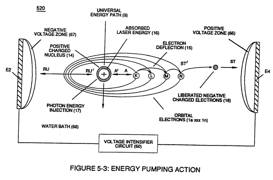
(520) of Figure (4-3) · Funneling Effect
-
Carries this number · Energy Pumping Action
-
Carries this number · Energy Pumping Action
-
(500) of Figure (5-1) · In Application of Usage
-
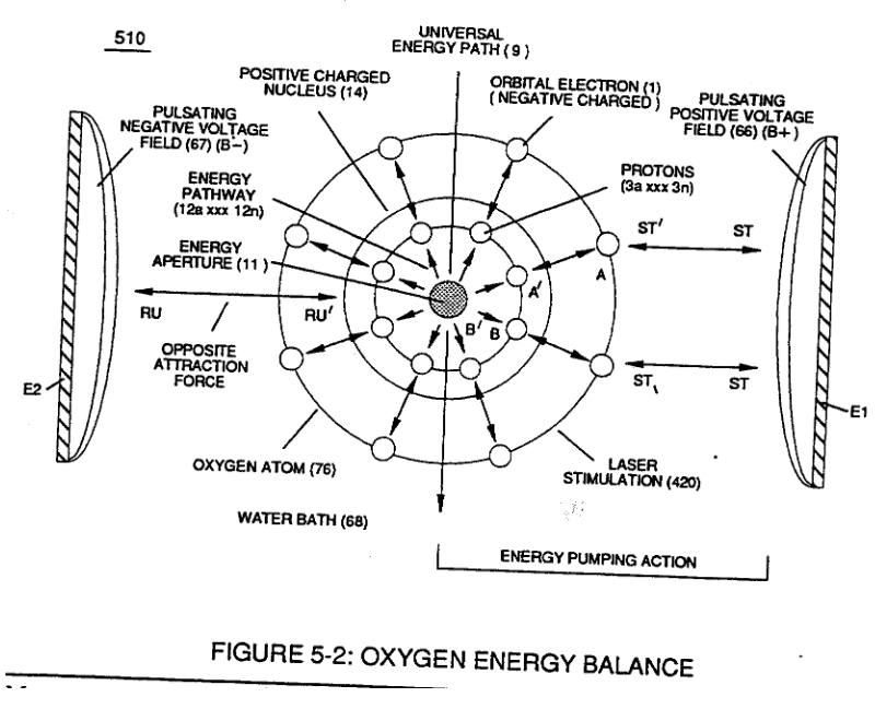
(510) of Figure (5-2) · In Application of Usage
-
Carries this number · Illustrations
-
Carries this number · Illustrations
-
Carries this number · Illustrations
-
coil-structures (580) of Figure (6-1) · Voltage Intensifier Coil-Assembly
-
Hydrogen Fracturing Process (520) of Figure (5-3) · Voltage Intensifier Coil-Assembly
-
(580) of Figure (6-1) · Inductance (FL)
-
(547) of Figure (5-9) · Inductance Reactance (Rs - Cd - FL)
-
(580) of Figure (6-1) · Multi-layer Coil
-
(547) of Figure (5-9) · Transformer Action
-
(520) of Figure (5-3) · 8-2 - Traveling Voltage Wave-Guides
-
Energy Pumping Action (520) of Figure (5-3) · WFC Development Objectives
-
Energy Priming Stage (500) of Figure (5-1) · Propagating Electrical Stress
-
(580) of Figure (6-1) · Voltage to Amp Differential Ratio
-
... emitting Coherent Energy Wave-Form (917), as so illustrated in (980) of Figure (10-2). · Optical Thermal Lens
-
Carries this number · WFC 429 - Illustrations
-
Carries this number · The Atom Functioning as an Energy Transporter
-
WFC Figure (5-1) · WFC Atomic Degaussing Process
-
Carries this number · WFC 430-2 Illustrations
-
Carries this number · WFC 430-2 Illustrations
-
energy aperture (7) of Figure (5-1) · Voltage Flexing Process
-
(1030) of figure (11-3) · Voltage Flexing Process
-
(500) of Figure (5-1) · Voltage Flexing Process
-
Differential Voltage Wave-Guild (1040B) · Electrical Crossover Switching Circuit
-
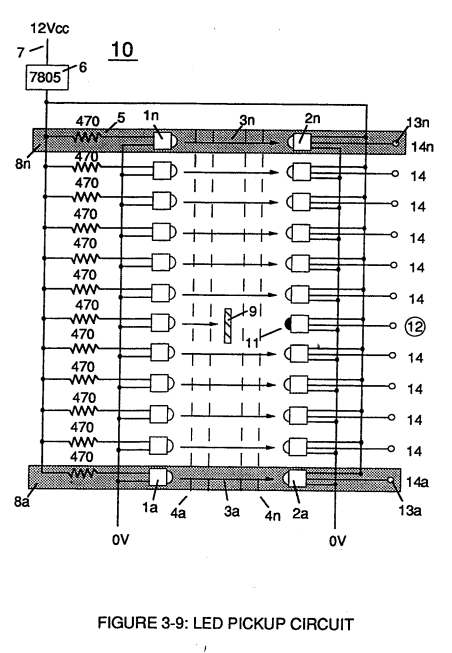
Led Pickup Circuit (10) of Figure (3-9) · Laser Accelerator Assembly
-
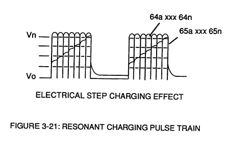
Figure (3-21) · Voltage Amplitude Control Circuit (50)
-
Figure (3-21) · Voltage Intensifier Circuit (60)
-
The figure it sits on · Voltage Dynamics
-
The figure it sits on · Gas Processor
-
The figure it sits on · WFC 422DA - Illustrations
-
The figure it sits on · WFC 422DA - Illustrations
-
The figure it sits on · Voltage Intensifier Coil Assembly
-
The figure it sits on · Differential Air-Gas Inlet Control
-
The figure it sits on · Water Fuel Injector (Taper Resonant Cavity Chamber)
-
(520) in Figure (5-3) · Resonant Propagation
-
(520) of Figure (5-3) · In Application of Usage
-
(520) of Figure (5-3) · Solar Energy Actuator
-
The figure it sits on · Illustrations
Where it is named · 11
Laser Accelerator Assembly 6×
-
GaAs infrared emitting diode (1)
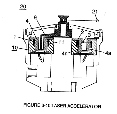
Laser Accelerator Circuit (10) of Figure (4) which is a component part of Laser Accelerator Assembly (20) of Figure (3-10) uses a GaAs infrared emitting diode (1) of figure (3-9) to trigger a SDP8611 Optoschmitt light receiver (2) of Figure (3-9) from quiescent state ( output logic high ... …
-
two infrared devices (1)
The Derate linearly of light intensity is approximately 1.25mWj degree C above 25 degree C at a spatial distance of .500 inches between the two infrared devices (1)(2) of Figure (3-9) as to Figure (3-10).
-
led (1)
Transmitted light source (3) is turned-on when a electrical power source of 5 volts is applied to the led (1) through dropping resister (5) by way of voltage regulator (6) connected to the car electrical system (7).
-
matched infrared devices (1)
Together, the matched infrared devices (1)(2) with optical lens (4) forms optical circuit (8) of Figure (3-9).
-
matched infrared devices (1)
To perform a switch-logic function, light - gate (9) of Figure (3-9) as to Figure (3-10) is inserted between the matched infrared devices (1)(2) and moved in a linear displacement from one optical circuit (8x) to another optical circuit (8xx), as illustrated in Figure (3-9)(3-10) as to Figure (3-7).
-
matched infrared devices (1)
Opposite placement of the matched infrared devices (1)(2) prevents bogus or false triggering of "low" logic state (12) during light-gate displacement (9a xxx 9n) of Figure (6)(7) and (8).
Voltage Amplitude Control Circuit (50) 1×
-
one (1)
Variable voltage range (32a xxx 32n) from one (1) up to twelve (12) volts (regulating battery voltage) is applied across primary coil (26) of Voltage Intensifier Circuit (60) of Figure (3-21).
Energy Pumping Action 4×
-
negative charged hydrogen electron (1)
Applied voltage fields (66-El/67-E2) causes and forms both opposite attraction forces (ST - ST') and (RU - RU') across exposed Hydrogen Atom (77) since the negative charged hydrogen electron (1) is attracted and deflected toward stationary positive voltage field (66);
-
orbital electron (1)
... applying and superimposing electrical tension (4) onto opposite attraction force (AA') that exist between the negative charged orbital electron (1) and positive charged Proton (3)
-
hydrogen electron (1)
Repetitive pulsing of applied voltage fields (66/67), now, oscillates Energy Aperture (7) to emit even a greater amount of Universal Energy (9a xxx 9n) into the energy spectrum of the proton nucleus (3) to be absorbed ... thereby, increasing the energy level of hydrogen atom still further .... deflecting hydrogen electron (1) to a higher energy state, as illustrated in (520) of Figure (5-3).