patent · US4323052A
Solar energy system
6 April 1982
Page 1 — bibliographic record
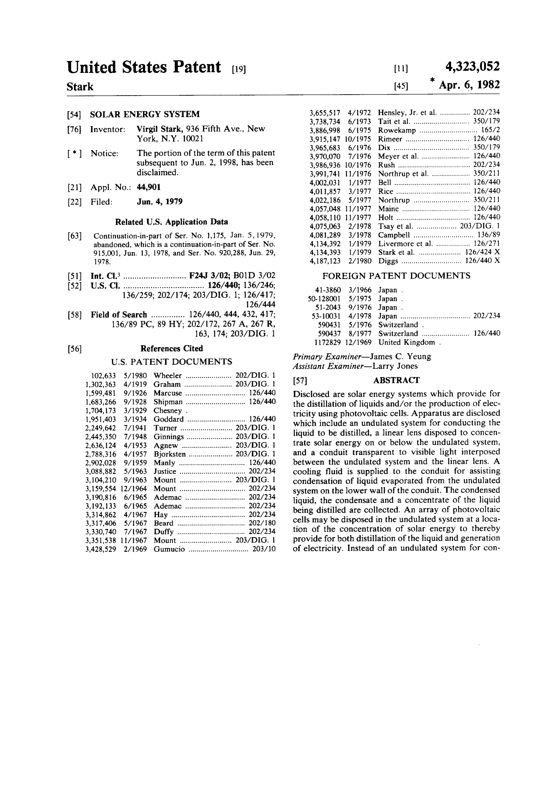
United States Patent (19) 11) 4,323,052 Stark (45) " Apr. 6, 1982 54) SOLAR ENERGY SYSTEM 3,655,517 4/1972 Hensley, Jr. et al................ 202/234 3,738,734 6/1973 Tait et al. ............................ 350/179 (76 Inventor: Virgil Stark,936 Fifth Ave., New 3,886,998 6/1975 Rowekamp ............................. 65/2 York, N.Y. 10021 3,915, 147 10/1975 Rimeer ...... ... 126/440 3,965,683 6/1976 Dix ...................................... 350/179 * Notice: The portion of the term of this patent 3,970,070 7/1976 Meyer et al. ... 126/440 subsequent to Jun. 2, 1998, has been 3,986,936 10/1976 Rush ................. ... 202/234 disclaimed. 3,991,741 11/1976 Northrup et al... ... 350/21 4,002,031 1/1977 Bell ................... ... 126/440 (21) Appl. No.: 44,901 4,011,857 3/1977 Rice ........... ... 126/440 (22 Filed: Jun. 4, 1979 4,022,186 5/1977 Northrup ... 350/21 4,057,048 11/1977 Maine ... ... 126/440
Related U.S. Application Data 4,058,110 1 1/1977 Holt ..................................... 26/440
63) Continuation-in-part of Ser. No. 1,175, Jan. 5, 1979, 4,081,289 3/1978 Campbell ............................. 136/89 abandoned, which is a continuation-in-part of Ser. No. 4,134,392 1/1979 Livermore et al. ... 126/271 915.001, Jun. 13, 1978, and Ser. No. 920,288, Jun. 29, 4,134,393 1/1979 Stark et al. ....... ... 126/424 X 1978. 4,187,123 2/1980 Diggs .............................. 126/440 X 51) Int. Cl. ............................ F24J 3/02; B01D 3/02 FOREIGN PATENT DOCUMENTS (52) U.S. Cl. .................................... 126/440; 136/246; 41-3860 3/1966 Japan .
136/259; 202/174; 203/DIG. 1; 126/417; 50-128001 5/1975 Japan .
58) Field of Search ............... 126/440, 444, 432, 417: 53-10031 4/1978 Japan ................................... 202/234 136/89 PC, 89 HY; 202/172, 267 A, 267 R, 590431 5/1976 Switzerland.
163, 174; 203/DIG. 1 590437 8/1977 Switzerland ........................ 26/440
Assistant Examiner-Larry Jones 102,633 5/1980 Wheeler ....................... 2O2/DIG. 1 (57) ABSTRACT
1,599,481 9/1926 Marcuse .............................. 126/44O Disclosed are solar energy systems which provide for 1,683,266 9/1928 Shipman .............................. 126/440 the distillation of liquids and/or the production of elec 1,704,173 3/1929 Chesney . tricity using photovoltaic cells. Apparatus are disclosed 1,951,403 3/1934 Goddard ............................. 126'440 which include an undulated system for conducting the 2,249,642 7/1941 Turner ...... ... 203/0IG. 1 2,445,350 7/1948 Ginnings. ... 203/DIG. liquid to be distilled, a linear lens disposed to concen 2,636, 124 4/1953 Agnew ..... ... 203/DIG. 1 trate solar energy on or below the undulated system, 2,788,316 4/1957 Bjorksten..... ... 203/DIG. 1 and a conduit transparent to visible light interposed 2,902,028 9/1959 Manly ...... ..... 126/440 between the undulated system and the linear lens. A 3,088,882 5/1963. Justice ................................. 202234 cooling fluid is supplied to the conduit for assisting 3,104,210 9/1963 Mount .. 2O3/DIG. condensation of liquid evaporated from the undulated 3, 159,554 12/1964 Mount ...... ..... 202/234 system on the lower wall of the conduit. The condensed 3, 190,816 6/1965 Ademac .............................. 202A234 liquid, the condensate and a concentrate of the liquid 3, 192,133 6/1965 Ademac .............................. 202/234 being distilled are collected. An array of photovoltaic 3,314,862 4/1967 Hay ..................................... 202234 cells may be disposed in the undulated system at a loca 3,317,406 5/1967 Beard ... ... 20218O 3,330,740 7/1967 Duffy ... ..... 202234 tion of the concentration of solar energy to thereby 3,351,538 11/1967 Mount ...... 203/DIG. 1 provide for both distillation of the liquid and generation 3,428,529 2/1969 Gumucio .............................. 203/10 of electricity. Instead of an undulated system for con
Page 2
ducting the liquid to be distilled, in one embodiment, a disposed in the other with a fluid being circulated first transparent tube is disposed in a second transparent through each tube and insulation surrounding the lower tube. The liquid to be distilled evaporates in the first portion of the tubes. Photovoltaic cells may be disposed transparent tube and is condensed on the upper wall in the innermost tube which is transparent. thereof which has an outer surface in contact with the cooling fluid. If desired, photovoltaic cells may also be disposed in the first transparent tube. In another dis closed embodiment, a collector comprises tubes one 36 Claims, 27 Drawing Figures
Page 3
Drawing sheet — no readable text.
Page 4
Drawing sheet — no readable text.
Page 5
Drawing sheet — no readable text.
Page 6
Drawing sheet — no readable text.
Page 7
Drawing sheet — no readable text.
Page 8
Drawing sheet — no readable text.
Page 9
Drawing sheet — no readable text.
Page 10
Drawing sheet — no readable text.
Page 11
Drawing sheet — no readable text.
Page 12
Drawing sheet — no readable text.
Page 13
Drawing sheet — no readable text.
Page 14
Drawing sheet — no readable text.
Page 15
Drawing sheet — no readable text.
Page 16
Drawing sheet — no readable text.
Page 17
Drawing sheet — no readable text.
Page 18
Drawing sheet — no readable text.
Page 19
to preheat the liquid. The heat exchanger is also located
SOLAR ENERGY SYSTEM to minimize pressure in the conduit.
In accordance with another disclosed embodiment of
RELATED APPLICATIONS Ser. No. 915,001, the sets of Fresnel lenses are arranged This application is a continuation-in-part of my co 5 so that the elongated focus of at least one set is substan pending application Ser. No. 1,175 filed Jan. 5, 1979, tially parallel to the axes of the compartments in the now abandoned which is a continuation in-part of my container and the elongated focus of at least one other co-pending applications Ser. Nos. 915,001, filed June 13, set is arranged so that the elongated focus is transverse 1978 and 920,288, filed June 29, 1978, the disclosure of 10 to the axes of the compartments and extends into vary which is hereby incorporated by reference. ing depths of liquid in the container. The two sets of
BACKGROUND OF THE INVENTION
Fresnel lenses are arranged at an angle to each other so that they meet along an apex with each set having a
This invention relates to a solar energy system in lower end.
general and more particularly to solar energy system 15 According to another aspect of that disclosure, the utilizing lens systems to concentrate the rays of the sun. bottom of the compartment containing the liquid to be In U.S. Pat. No. 4,134,393, of which I am a co-inven distilled is blackened to allow absorption of solar en tor and the sole assignee, and in pending application ergy and enhance the heating of the liquid. Ser. No. 807,513 filed June 20, 1977 and Ser. No. Furthermore, in my co-pending application Ser. No. 845,862 filed Oct. 31, 1977 (now U.S. Pat. No. 920,288 filed June 29, 1978, solar energy is concentrated 4,194,948), of which I am sole inventor, solar energy by lens means in an elongated focus located substan distillation apparatus are disclosed in which a part of the tially in or on the surface of, and substantially along at heat of condensation of the condensing liquid is recov least one conduit system by a lens means which is piv ered. In the disclosed embodiments in those applica oted at least about a first axis of the least one conduit. tions, the heat of condensation is transferred to a fluid in The conduit system includes an inner conduit enclosed a fluid lens disposed over the liquid to be distilled in 25 by an enclosure with the enclosed inner conduit and clined to provide a bottom surface on which the evapo enclosure enclosed by an outer conduit. A collector rated liquid is condensed and flows to be discharged having inner and outer conduits which are transparent from the lower end thereof.
At locations where a lens inclination of greater than at least in part with photovoltaic cells disposed in the inner conduit and a fluid which absorbs substantial 20 is desirable to increase collection, the system oper ates at reduced efficiency since the fluid lens is limited amounts of infrared solar energy circulated in the outer conduit is utilized.
to angles of inclination of less than about 20. In accordance with Ser. No. 920,288, the apparatus is Fluid lenses also have other drawbacks, which in accordance with my appliction Ser. No. 915,001, filed disposed South so the first axis extends generally in the North direction, so that the lens means can track the sun
June 13, 1978, are substantially overcome and improved on a daily basis, the
conduit remaining stationary as the solar energy distillation apparatus obtained by provid lens means is pivoted.
ing solar distallation apparatus in which the solar en According to that disclosure, the lens means com ergy is concentrated inthe liquid to be distilled and prises at least one Fresnel lens having prisms extending double plate conduit means, with an upper and a lower substantially parallel to the first axis. wall between which a heat exchange fluid flows are 40 provided to condense the evaporated liquid vapor on a In one embodiment disclosed therein the apparatus surface thereof, the conduit means being disposed inter comprises a plurality of adjacently disposed collectors mediate the liquid to be distilled and lens means for and a plurality of adjacently disposed lens means. Ac concentrating the solar energy in the liquid. cording to this embodiment, the lens means and collec The concentrated solar energy causes the liquid to 45 tors are pivoted about an axis only on a daily basis with evaporate with the vapor impinging and being con the at least one conduit remaining stationary regardless densed upon the outer surface of the lower wall of the of season.
conduit means, the condensed liquid flowing along the In accordance with still another aspect of that inven outer surface of the lower wall to the lower end thereof tion, an elongated conduit system for collecting solar and falling therefrom into a container, a substantial part 50 energy in an elongated focus is provided in which the of the heat of condensation of the condensing vapor elongated focus is located substantially in or on and being absorbed by the fluid in the conduit means. substantially along the conduit system, which comprises According to one embodiment of Ser. No. 915,001, two elongated conduits for passing fluids therethrough the lens means comprise a plurality of sets or series of and an enclosure for a first of the conduits, the conduits Fresnel-type lenses arranged to provide an elongated 55 and enclosure being disposed so that an inner of the narrow focus. The container includes a plurality of conduits containing a fluid therein is enclosed by the baffles dividing the container interior into a plurality of enclosure, there being a dead space in the enclosure distillation compartments for the liquid to be distilled surrounding the inner conduit, and an outer of the con and is inclined so that the compartments are offset in duits containing a fluid therein encloses the enclosure height. The elongated focus of each series of Fresnel 60 and inner conduit, at least part of the enclosure and lenses may therefore be located in and along a different outer conduit being transparent with transparent por compartment. tions thereof being aligned and adapted to transmit the An expansion tank for the heat exchange fluid in the solar energy in the elongated focus therethrough. The conduit is located so as to provide minimal pressure inner conduit is opaque with a darkened outer surface within the conduit. 65 and the dead space in the enclosure preferably contains A heat exchanger is also provided to transfer the heat air, the elongated focus being located substantially on recovered in the heat exchange fluid circulated in the and substantially along the outer surface of the inner conduit to the liquid being introduced into the container conduit which absorbs the solar energy and transmits
Page 20
heat to the fluid therein. In the preferred embodiment, ing the cost which would be associated with a separate the inner conduit comprises metal piping and the enclo solar installation for producing electricity. Further sure and outer conduit comprise glass tubing. The inner more, where concentration of solar energy is used as is and outer conduits carry heat exchange fluids while the the case with the present invention, the production of dead space around the inner conduit provides insulation 5 electricity can be up to for instance 40 times that which for the fluid therein. it would be without concentration. For example, the According to an aspect of my previous application average yearly production of electricity with concen Ser. No. 920,288, photovoltaic cells which produce tration will be, for example 3 Watts per cell of, for electricity from luminous solar energy of about 0.4 to example, 5 cm X5 cm, compared with about 0.06 Watts about 0.7 microns wavelength are installed in an inner 10 per cell for cells exposed to the sun without concentra conduit which is transparent at least in part of an elon tion. Cost estimates have shown that installing an array gated collector. The elongated focus of a Fresnel lens is of photovoltaic cells in a distillation unit of the present located on the cells in the inner conduit. The inner invention permits saving all of the cost of the solar conduit is enclosed by an outer conduit which is trans system otherwise required by the photovoltaic cells. parent at least in part. 15 Put another way, it reduces by about half the total cost This arrangement increases the production of elec of the photovoltaic cell system when the solar system tricity by the photovoltaic cells since their efficiency is need to concentrate the solar energy is considered. not substantially reduced by the heat that would be Thus, the present solar energy system uses a single generated by infrared solar energy otherwise reaching concentrating means, i.e., lens system, which supplies the cells. In the preferred embodiment, the fluid is wa- 20 energy both for distillation and for generating electric ter. ity.
SUMMARY OF THE INVENTION
Furthermore, the absorption of infrared rays by the fluid in the conduit means and by the water being dis
It is the object of the present invention to improve the tilled which circulates above and around the photovol efficiency of systems of the above described nature. 25 taic cells permits the production of electricity at higher In accordance with one embodiment of the present efficiencies. As temperature goes up the efficiency of invention which constitutes an improvement on the silicon photovoltaic cells goes down. At a temperature distillation apparatus of the aforementioned Ser. No. of 200 C. the efficiency is zero, and the cells melt. 915,001, what in the embodiment thereof were rela However, because of the absorption of the infrared tively large and deep distillation compartments are re- 30 radiation by the circulating fluid and by the water being placed by an undulated plate or plurality of adjacent distilled, temperatures are maintained lower. plates on top of an insulating base. The photovoltaic cells can preferably be encapsu In accordance with a further feature of this embodi lated in a transparent plastic or glass cover of similar ment of the present invention, a single panel or plurality shape either rectangular or round so as to protect the of adjacent panels made of blackened flexible plastic or 35 cells from saline water which will flow above such the like, such as isobutyl, are disposed over all or bot cover. The cells can also be enclosed in a transparent tom part of the plates. They are to be attached to the tube in which distilled water such as cooled condensate plates in a removable manner which will permit taking produced by a distillation unit can circulate and further them out to remove deposits which may form on them. absorb heat generated by the infrared rays. Such a heat Furthermore, as described above, it is preferred that 40 exchange can reduce the temperature of the condensate the undulated plates be placed above the focal area of from about 75 C. to, for example, about 30° C. With maximum concentration obtained from the Fresnel this arrangement, heated salt water will not flow around lenses. This permits a wider spread of the heat converg the photovoltaic cells and form deposits thereon. And, ing from the lens on the undulated plates so that a wider furthermore, the cells instead of being surrounded by area of the plates is heated. Another feature of this 45 fluid at a temperature of up to 75 C., will be sur embodiment is to allow the fluid circulating between rounded by fluid at a temperature of only, for example the double plates located between the Fresnel lenses 40° C. The efficiency of electricity production is gener and the distilling basin with undulated plates to spread ally reduced by about 0.4% for every degree C. in all along the surface between the double plates and to crease in temperature above, for example, 30° C. By selectively regulate the quantity of fluid circulating, 50 encapsulating or enclosing the cells and circulating thus controlling the temperature of the fluid by restrict cooling water around them, the cells will be maintained ing the bottom passage of the section at an extreme end at their optimum temperature for efficiently producing of the plates leaving a small opening for relasing the electricity and at the same time the cells will be pro fluid. tected from any corrosion effects of the salt water or In the same type of system, in accordance with an- 55 salt deposits. Such encapsulation and circulation of other feature of the present invention photovoltaic cells condensate may be used in any of the embodiments are installed in one or more bottoms or valleys of the subsequently discussed, which employ solar cells. undulated plates at the locations where the focus area of Furthermore, as previously disclosed in the afore the Fresnel lens are most concentrated. As in my previ mentioned Ser. Nos. 915,001, and 920,288 it is preferred ously disclosed systems, the lenses are supported for 60 that the lenses track the sun. Preferably, such tracking movement to track the location of the sun using either will be done only for the elevation around a North the system described in my previous applications or South axis. The deviation for seasonal locations of the systems to be described in more detail herein. Again, as sun of a maximum angle of 23.5° C. from equinox to with my other system, although Fresnel lenses are pre solstice will take place on each side of the central axis of ferred for a number of reasons, liquid lenses may also be 65 the focal line without elevation tracking. The seasonal used. changes will be along the axis of the focal line if eleva With such an arrangement the photovoltaic cells will tion tracking is provided. Elevation tracking can be produce electricity at the minimal additional cost avoid provided by moving the lens about the axis of the focal
Page 21
line oriented along a North-South axis. Care should be conduit against which the evaporated water condenses taken that the distances between the lenses are such that are also required to maintain condensation and carry no lens shades the adjoining one as they are tilted. away that heat. For example, the fluid circulating in the As disclosed in my previous applications, a central conduits will typically be heated from 30° C. to 65 C. station with electric cells or other means such as special by the vapor from the water being distilled which is at clocks, a computer or the like can be utilized to activate about 75 C. The quantity of heat which is recovered by an electric motor which will move a series of lenses to this fluid may be approximately 3200 kcal/m/day. The be oriented by pulleys and chains or other means. Such fluid circulating in the conduits after being heated from apparatus is disclosed in my aforementioned Ser. No. O it30 istorecirculated.
65° C. must be cooled back down to 30° C. before
This cooling is carried out by the 920,288. water which is being distilled. Thus, in order to bring Much in the manner disclosed in the aforementioned
Ser. No. 915,001 series of linear Fresnel lenses which about a temperature drop of 35 C. and to remove the are arranged alternately along the North-South and heat which is recovered by this fluid, it is necessary that East-West axes may be used. the amount of water being distilled equal 3200 divided In accordance with a further embodiment of the pres 15 by 35 = 91.4 Liters/m2/day. It requires 540 kcal/Liter ent invention an improved method of tracking is pro plus the sensible heat, for instance 580 kcal/Liter to vided. In accordance with this embodiment of the in evaporate one liter of water. Solar energy of, for exam vention the Fresnel lenses or fluid lenses are enclosed in ple 3200 kcal/m2/day would be produced, at 580 frames which are preferably metallic such as anodized kcal/L, about 5.5 liters/m2/day, plus the heat recuper aluminum or steel, or the like. Each of the frames have ated from the condensation. The preheating of the mounted thereon, at each corner thereof, small wheels, water being distilled will be, for example, from 20° C. to 35° C. The quantity of distilling water will be the quan ball bearing tracks, or similar means which ride in a rail tity system having a sinusoidal shape. The linear Fresnel, or noted above, i.e., 91.4 Liters/m2/day. Assuming an fluid lenses in the frame are spaced and coupled together evaporation including incorporation of heat of about 10 in such a manner that they move together so that, all 25 Liters/m2/day, the quantity of the brine will be of the lenses will be at the same position, i.e., all lenses at the order of 81 L/m2/day.
peak of the sinusoidal track, or all lenses on one side of tionAsapparatus noted, the brine, after passing through the distilla will have a temperature of approximately the peak or the other. By moving the lenses from one side of the peak over to the other, it is possible to easily 80' C. More of the water in the hot brine can be evapo track the sun from East to West. The same type of 30 rated reducing the temperature of the brine, for exam control means as described in my aforementioned Ser. ple, from 80° C. to 40 C. and thus producing additional No. 920,288 can be used for operating motors driving distilled water, either during the day, in another adja cables which move all of the lens frames in unison. cent unit, (adding solar energy for further evaporation) Unlike the systems previously disclosed in my Ser. No. or during the night, or days without sunshine by recy 920,288 where large masses needed to be moved about 35 cling the brine, instead of the salt water, and recuperat an axis, with the tracking system of the present inven for ing a part of its heat. Brine released during the nights at tion, only a relatively small force is required since a instance 55' C. can be added to the salt water in large part of the mass of the lenses and frames is sup order to recover part of this heat. The production of ported on the wheels, and such mass is reduced by the distilled water will be greatly increased and its price gravity when tilted downward. The specific shape of 40 reduced by such a measure.
Through recycling of the brine, salt can be extracted the rails will be tailored to the specific local orientation therefrom required during the day. Preferably the frames, at the with an increased salt content after several end of the day, will be moved through their initial posi recyclings. For example, a recovery of over 10%, as tion, i.e., pointing East to be ready to start collecting opposed to the initial salt content of 3.5% is possible. energy in the morning simply through the use of the 45 Chemicals such as sodium chloride (for example 27000 reset switch activating an electric motor which drives ppm) natrium chloride, magnesium chloride (for exam in reverse. ple 3600 ppm), magnesium sulfate (for example 1600 The above system is independent of the requirement ppm) etc., could be obtained.
of an axis for rotation of the lenses which in some sys In accordance with a further feature of the present tems is spaced as much 40" from the lenses. In the pres 50 invention, provisions are made to store the fluid circu ent embodiment, the height of the railing above the lating in the conduit, the brine and the condensate, all in horizontal will be much smaller and the capacity of the selected quantities, in the space below the insulated electric motor, for the reasons noted above, will be panel on which the undulated plates rest. By storing correspondingly smaller. these fluid beneath the insulated plate, further insulation This tracking system can be used both with the dou 55 is provided reducing heat losses.
ble plate system and with systems using concentric In lieu of the undulated plate, an embodiment similar conduits. Furthermore, more than one lens can be to that in my aforementioned application Ser. No. mounted in a single frame. 920,288 in which the photovoltaic cell arrays are in In accordance with another feature of the present stalled inside of a transparent glass or plastic tube, in invention, provisions are made to recirculate the brine 60 serted in another transparent glass or plastic tube may obtained in the distillation apparatus both during the be used. Salt water or brine flows over and around the day and night and on days without sunshine. The brine array of photovoltaic cells in the inner tube. The focus obtained at the output of the distillation apparatus will from the Fresnel or fluid lens will preferably be under typically be at a temperature of 80° C. and its quantity the inner tube so that the area of solar rays is spread all will be for instance eight times as large as the water 65 over and concentrated on the photovoltaic cells. Vapor vaporized by solar energy alone. Furthermore, as previ resulting from the evaporation of the salt water or brine ously disclosed in my aforementioned application Ser. condenses on the inside walls of the inner tube which is No. 915,00 larger quantities of the fluid carried in the preferably tilted at the angle of the latitude of location
Page 22
plus 10. Condensate flows along the inside wall of the from East to West. The tube assembly is fixed and does tube and is collected in a container at its outlet. A fluid not move with the mirrors and Fresnel lens. With this such as distilled water circulates between the inside tube system, increased radiation above that with simply a and the outside tube to recover the heat of condensa Fresnel lens is achieved through the used of mirrors. tion. Furthermore, in the manner described above, the The concentration of solar energy in a focus area will be fluid will absorb most of the infrared rays allowing much higher, thus making this embodiment of special transmittance of most of the visible rays which are the interest to the production of electricity from photovol only ones which produce electricity in the voltaic cells. taic cells, since, as noted above the electricity produc The condensate also absorbs infrared solar rays and tion is almost directly proportional to concentration. heats the circulating fluid which heat is recovered in the O As is the case in the other embodiments, the fluid manner described above. Encapsulation of the cells and cooling with condensate may be also accomplished as circulating between the conduits acts to absorb infrared radiation to maintain the photovoltaic cells at a low above.
Heated fluid which flows between the tubes then temperature. Furthermore, as with all embodiments of the present invention, fluid lenses rather than Fresnel flows into a collector and this heat can be used for 15 lenses may be provided.
preheating the salt water, for example. The brine flows In accordance with a further embodiment of the in into another collector and can be recycled in the man vention, a tubular conduit consisting of two or more ner described above.
In accordance with another feature of this embodi tubes such as disclosed in my aforementioned applica ment of the invention, the Fresnel lenses or fluid lenses tions, is disposed above a semicylindrical or parabolic reflecting surface. A Fresnel lens of large size, for in which concentrate the solar energy on the photovoltaic stance of aperture up to 860 mm, is disposed above the cells are supported for rotation to follow the East-West tube assembly movement of the sun. The point of rotation is preferably sun, not only and acts to concentrate the rays of the about the focus of the lens. The tube is supported above surfaces of the structuretube on the assembly, but also on the below the tube assembly which a member on the inside of which there is a reflective 25 is mirrored. The focus of the lens is located below the coating such as aluminized paint or sheet to reflect Solar mirrored rays and increase irradiation. surface. As a result, energy is concentrated The whole structure, save the tubes, moves around an both from above, i.e., direct rays from the lens, and axis located along the center axis of the tube. A counter from below, rays which are reflected from the mirrored weight is provided so that the weight of the Fresnel lens 30 surface. As with other embodiments, the structure in and its frame and support times the distance from the cluding the lens and mirrored surface is rotated about lens to the axis of rotation will be similar to the weight the axis of the tube assembly to track the sun. of the counterweight times its distance to the axis to This embodiment is particularly useful for several permit a minimum effort of rotation. The counterweight applications. For example, in the case of a triple conduit can be either of steel or provided in the form of a con 35 system including an inner metallic conduit, it can heat a tainer filled with a heavy low cost material such as sand fluid circulating in the inside metallic conduit up to a or concrete. A plurality of such units can be disposed temperature of 300° C. Secondly, it can be used for adjacent each other and moved by a central unit and distilling water circulating in a transparent inner con electric motor as previously described in my aforemen duit as in previously discussed embodiments with vapor tioned application Ser. No. 920,288. condensing on the inside of the conduit. Furthermore, Once again, this combination permits water distilla as in previously discussed embodiments, photovoltaic tion combined with the production of photovoltaic cells cells may be provided inside a transparent conduit to without the use of the panel or plates of distilling appa produce electricity. Finally, the combination of distilla ratus used in the other embodiments, but using simply tion of water and production of electricity is possible. concentric tubes instead. 45 With this arrangement, the insulating collector which In accordance with another embodiment of the pres otherwise surrounds the tube assembly can be elimi ent invention, a conduit assembly such as the disclosed nated. When used for heating a fluid in the inner con in my aforementioned application Ser. No. 920,288 and duit, the fluid between the outer conduits will be circu as described above, is surrounded by longitudinal mir lated in a selective manner to absorb heat emitted by the rors having the necessary forms and sizes to carry out 50 fluid in the inner conduit, or by the solar rays reflected optiminzation of the collection of solar radiation. In this on the conduits, and will have a predetermined temper embodiment, incoming solar radiation is reflected by a ature of, for example, 75 C. so as to limit heat losses. first group of mirrors to a cylindrical mirror disposed Another embodiment of the invention provides re above a Fresnel lens. The cylindrical mirror reflects flective parabolic longitudinal mirrors of adequate radiation through the Fresnel lens which concentrates 55 shape, preferably made out of thin waterwhite glass or the radiation on the conduit system. The mirrors reflect similar reflective material. The solar rays will be re ing energy to the cylindrical mirror surround the con flected onto one or more tube assemblies of two or three duit system and additional energy therefrom is reflected tubes inserted one in another with fluids circulating in to the conduit system further concentrating the energy. the inside tube and between the outside and inside tubes. As with the previous embodiments, photovoltaic Provisions can be made to insert photovoltaic cells in cells can be installed inside the inner tube of such a the inside tube. Distillation of water can be provided as system. As with the previous embodiments described, described above. Fresnel glass lenses of large aperture this embodiment can be used in a heating system or a such as 84 cm wide and 240 cm large have excellent distillation system with or without photovoltaic cells. solar energy transmission of about 90% only in the Furthermore, as with other embodiments, the system middle; thereafter the transmission is successively lower of mirrors and Fresnel lens is supported for rotation such as to about 80% and thereafter lower, for example about a longitudinal axis coinciding with the axis of the 65–70% at the extreme ends. It is of interest to have inner tube in order to track the movement of the sun Fresnel lenses of smaller aperture for instance 60 cm
Page 23
instead of 84 cm (24' instead of 34') with an average which can be detented to allow only notch by notch solar energy transmission of about 85%. engagement avoiding speedy turning of the rotating In a further embodiment of the present invention disk.
several Fresnel lenses of 60 cm each for example, are Another embodiment of the present invention com installed adjacent each other on the same rotating frame 5 prises providing, as a concentrator of solar energy, glass and supports. The collector tube assembly is stationary Fresnel lenses having grooves of different types on the and the tubes then connected in series so that the fluid same lens body. Large Fresnel lenses of about 84 cm circulating in the tubes is progressively heated from one aperture and 240 cm long have very good solar ray tube to higher temperatures in the adjacent tube. The transmission of about 80-90% in the center part of mirrors under the tube assemblies are connected to 10 about 50 cm and lower decreasing transmission towards gether and rotated with the Fresnel lenses by a worm the ends of about 65-70%. In addition, because prismal gear drive. Scattered solar rays from one set of lenses grooves are not sharp, some solar rays are scattered and may be incident either on one mirror or partially on an do not reach the focus track, lowering the efficiency of adjacent one. Both the tube assemblies and insulation solar energy concentration.
and the worm gear drive will remain stationary. 15 In accordance with this aspect of the present inven A further embodiment of the present invention in tion only the central part of about 50-60 cm are used cludes providing a shock absorber or other means in and, on the same glass plate, side portions with properly case of high winds or gusts of winds acting on the rotat angled grooves are provided in order to direct the solar ing Fresnel lens which might otherwise destroy the rays to the same focus track as the central grooves. If rotation means which follow the East-West location of 20 the side parts of the lens are for instance 40-50 cm and the sun. have more grooves than the central part, duly oriented, The worm gear drive is activated by an electric this will provide a lens of 150 cm aperture for instance motor having, as a sensor, electric cells. The worm gear and only one focus target of 3 cm large, for instance. In acts on a circular gear with sockets attached to the such a case, the concentration ratio will be on the order supports moving the Fresnel lens system, mirrors and 25 of 50 times. This arrangement is of special interest for the counterweight. production of electricity with photovoltaic cells. In A stationary cylinder in which a piston is provided is deed, the electrical production will increase, with the connected to the worm gear; the cylinder is separated concentration ratio increasing 50 times. The Fresnel into two chambers each containing a fluid. At least one lens with the mirror under the one tube assembly and orifice is provided in the piston of the cylinder causing 30 the counterweight will turn to track the East-West daily the piston to move slowly in the cylinder following the location of the sun around the axis of the inside collec movements of the worm gear. tor tube. Several Fresnel units can be arranged in paral If a sudden gust hits the Fresnel lens rotating system lel and in series.
and the link to the piston pulled by the worm gear, the When arranged in parallel, several Fresnel lens units piston with its small orifice will slow down the move 35 may be arranged to have the same focus track thereby ment of the worm gear through the link since the fluid increasing the concentration ratio accordingly about 70 must pass through the small orifice and acts as a brake times or more. The mirror will have a large aperture slowing the movement of the piston and thereby the equal to one of the large Fresnel lenses of the parallel worm gear without affecting either the worm gear or array. The large mirrors of similar aperture of the large the electric motor. 40 Fresnel lens or lenses will receive the scattered or direct Absorber means of this type can be provided for solar rays and reflect them into the tube assembly in several Fresnel lens rotating units connected in series or creasing the solar collection efficiency and the concen parallel. Preferably such a shock absorber will be at tration.
tached on the rotating support above the counterweight The collector assembly of tubes is as shown in previ and under the stationary tube assembly. 45 ous disclosures with one metallic blackened conduit in In a further embodiment of the present invention the which a fluid heated by solar energy concentrated by a absorber cylinder can be provided, on one side, with lens system with the focus track on or under the metal special valve which will open at a selected pressure and lic tube or glass tube enclosed in a second transparent allow the fluid on the one side of the cylinder to drop glass tube spaced from the metallic or inside conduit by into a nearby cylindric container. 50 about 2 mm with air circulating in between. The glass The piston activated by the fluid on the opposite of tube is inserted into the third transparent tube. A second the cylinder, and not emptied, exerts pressure on the fluid circulates between second and third transparent Fresnel lens system together with the mirrors and coun tube. The fluid in the metallic or inside conduit heats the terweight and allows the rotating system to be moved outside fluid in addition to the heat which the outside to the initial morning position or last evening position 55 tube absorbs from the solar rays. The system thus pro reversed to the initial morning one; this will avoid dete vides a set of heat barriers limiting the heat losses espe rioration by wind gusts. cially for high heating temperatures of the inside fluid. The electric motor can be automatically stopped after However, the transmission of heat to the inside metallic the return of the system to the initial position; the fluid conduit is reduced by the reflection of the glass tubes can be pumped either automatically or manually, once 60 and by absorption of infrared rays by the outside fluid normal wind conditions prevail, into the side of the and the two glass conduits.
cylinder emptied after a wind gust has opened a pres An airspace must always be provided between the sure valve on this cylinder side. innermost tube in which a fluid is heated to high tem Other means can be provided for facing high winds perature and the intermediate glass tube surrounding it, and/or wind gusts which may prevail especially in des 65 and inside an outer tube, with a second fluid between ert areas; such other means may comprise springs on the intermediate and outside tube.
each side of the supporting means. These can be com An alternate solution utilizes a rectangular, instead of bined with a rotating disk moved by the worm gear round, inside metallic conduit. Another alternate solu
Page 24
tion is to provide at least two adjacent blackened metal large aperture and a movable longitudinal mirror under lic conduits inside the outer conduit. Another solution is the fixed tube assembly.
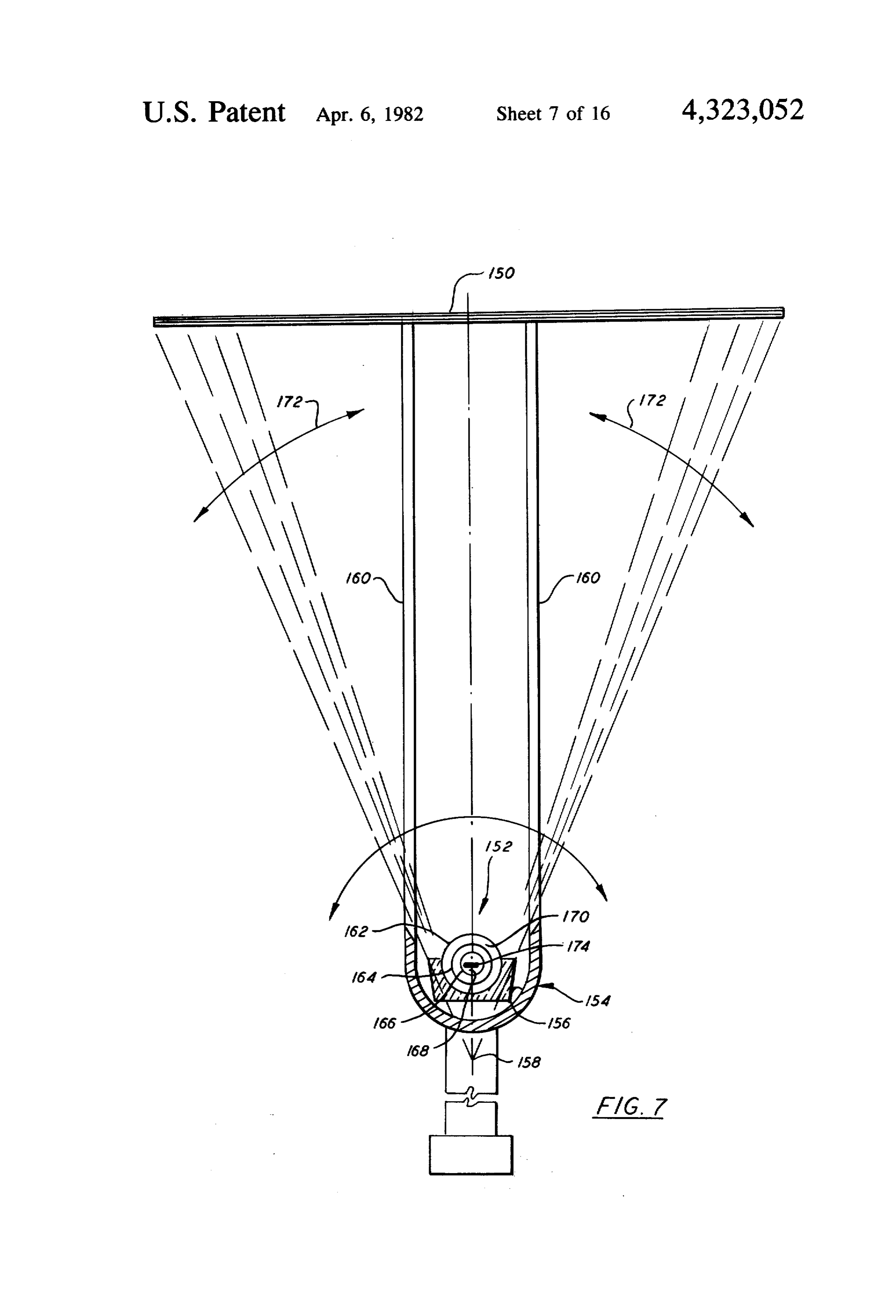
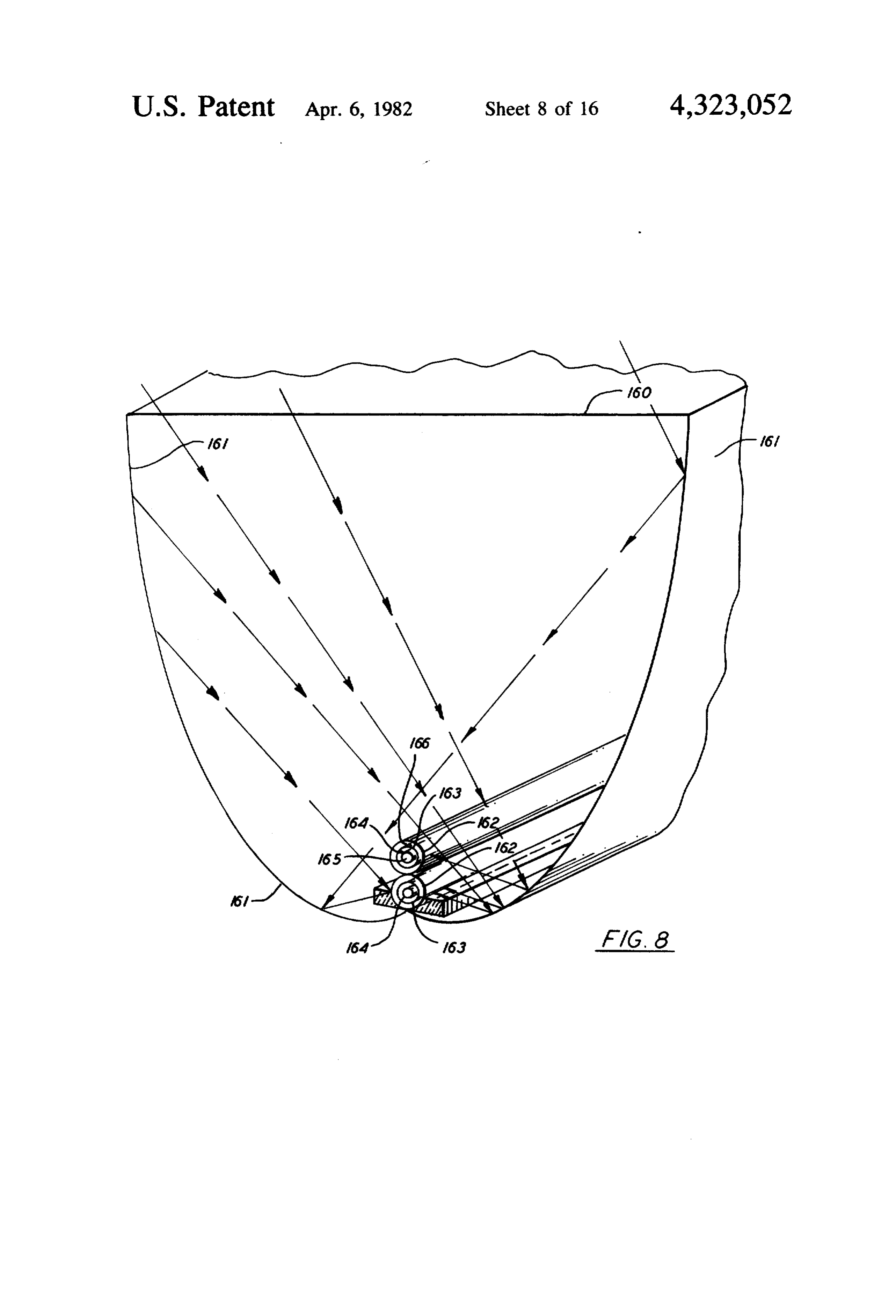
to provide, in the inside conduit, an array of photovol FIG. 8 is a perspective view of an embodiment of the taic cells, all having two controlled circulating fluids as present invention in which parabolic mirrors are uti above. An aluminized reflective mirror will be provided lized to focus solar energy on one or more tube assem below the conduit assembly. A counterweight will be blies.
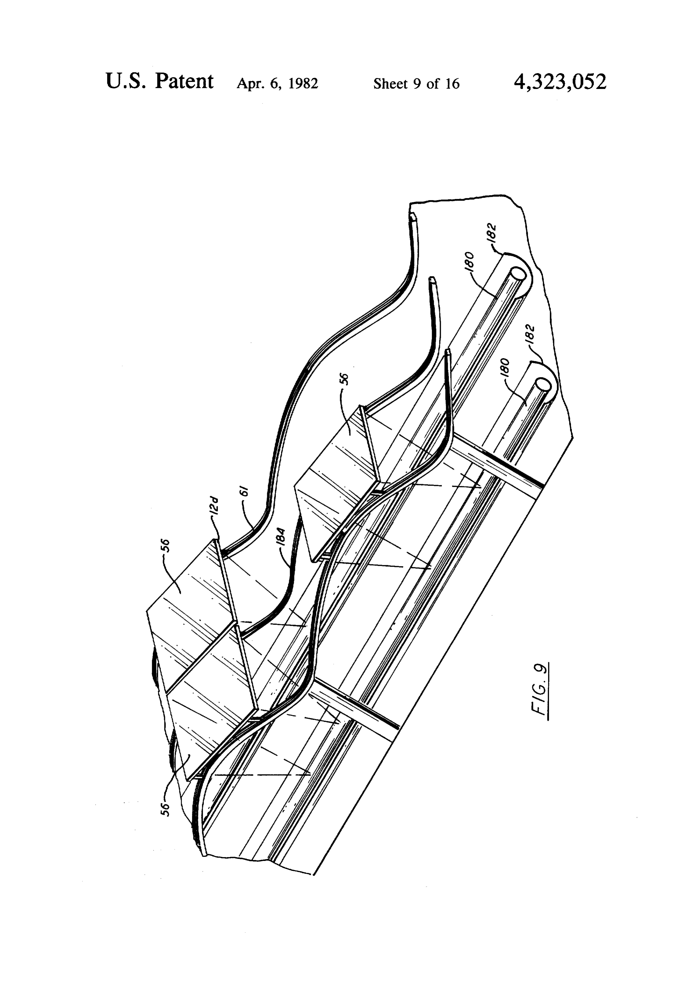
provided below such mirror and the conduit assembly. FIG. 9 shows a sinusoidal railing for tracking lenses The Fresnel or fluid lenses are rotated with the mirror, along their longitudinal dimension, side by side in series counterweight and supports around the axis of the in and parallel with a stationary collector tube assembly side conduit as indicated above. A security panel with O and reflective mirror and also shows providing adjacent an aluminized surface on the side of the collector is provided. The panel is adapted to drop on the collector Fresnel lenses being moved together with one cable common to the frames of several lenses.
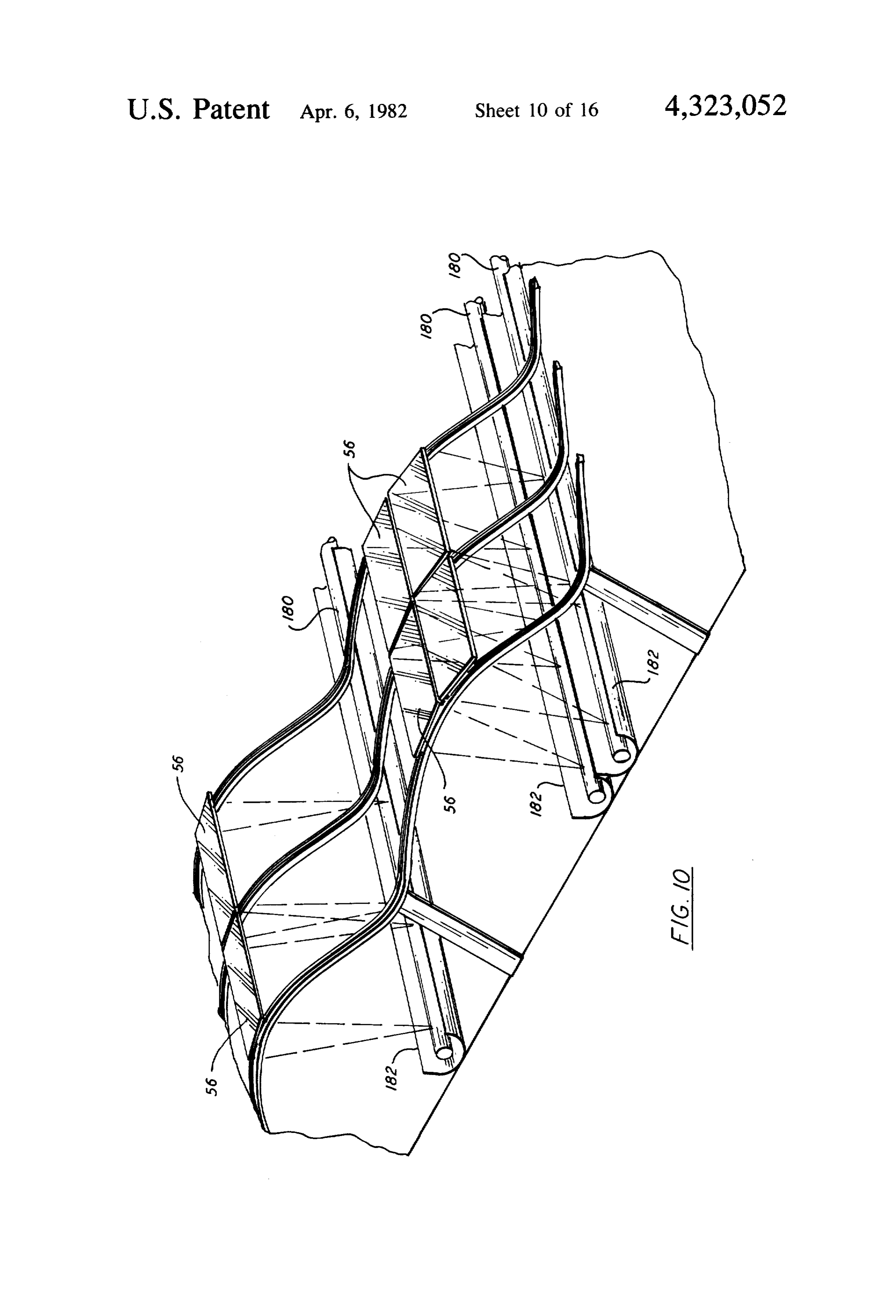
in case of overpressure or of a temperature higher than FIG. 10 shows a tracking system similar to that of selected. In certain cases the mirror below the tube
FIG. 9 with a sinusoidal railing moving in the lateral assembly will be omitted and instead the outside tube 15 direction of the Fresnel lens.
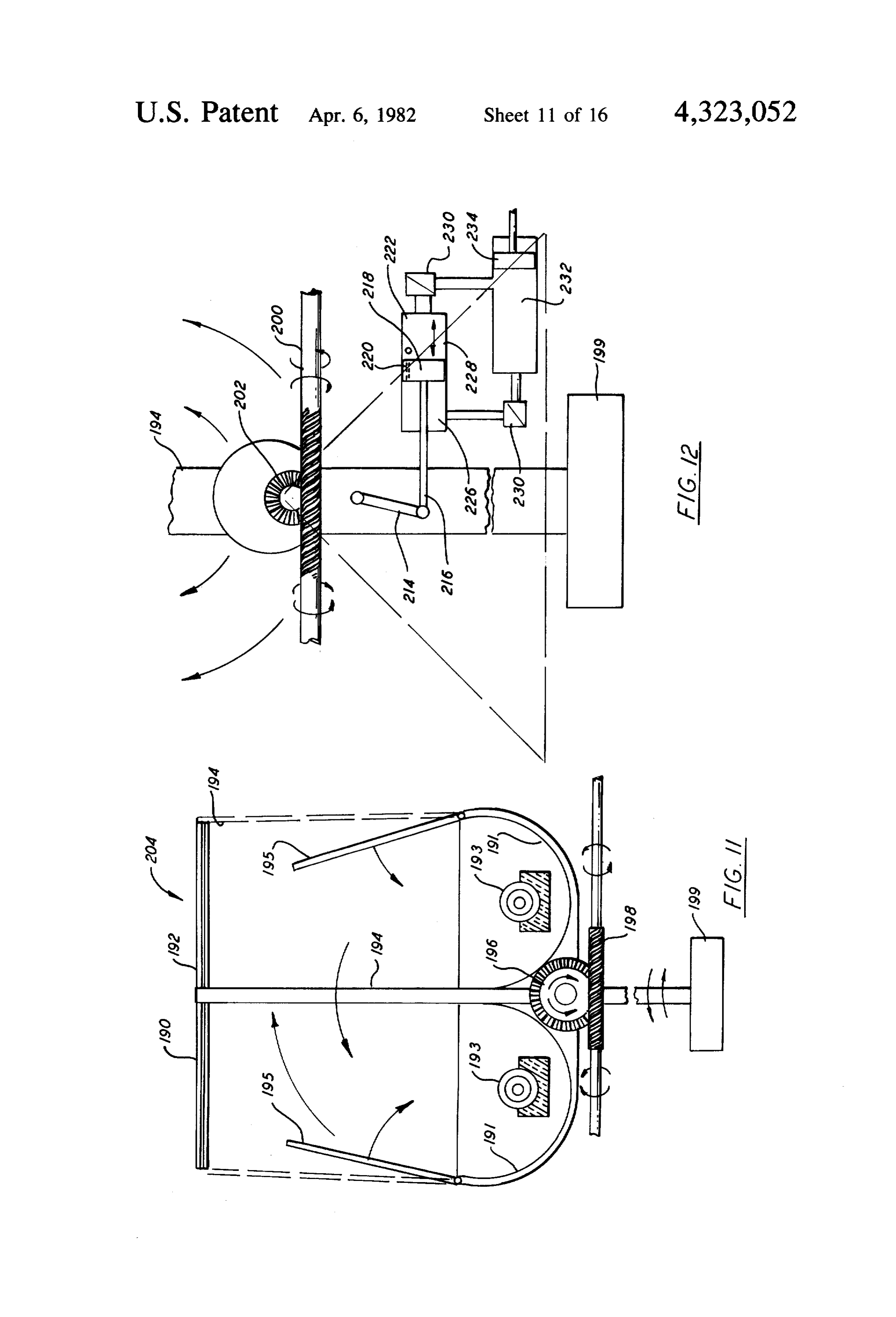
will be partially enclosed in an insulated unit filled with FIG. 11 shows two Fresnel lenses installed in the insulating material with the upper part opened to allow Same frame and rotating together with the mirrors. the solar rays to rach the focus track. The insulation partially surrounding the outside tube is preferably sta FIG. 12 shows the adjacent Fresnel lenses rotating tionary with the tube assembly whereas the mirror and together with a reflective mirror and the counterweight lens system rotate to track the sun. Selection of the moved by a stationary worm gear activated by an elec above alternate solutions will depend on the application arytric motor to track the location of the sun with a station of the solar energy to the metallic conduits. The barrier tube assembly.
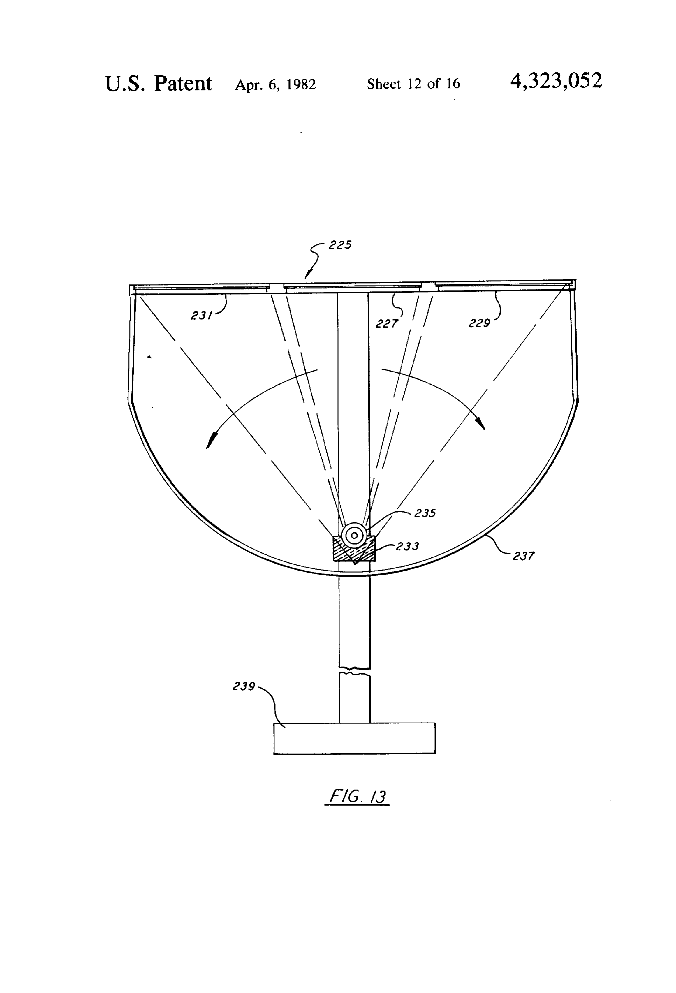
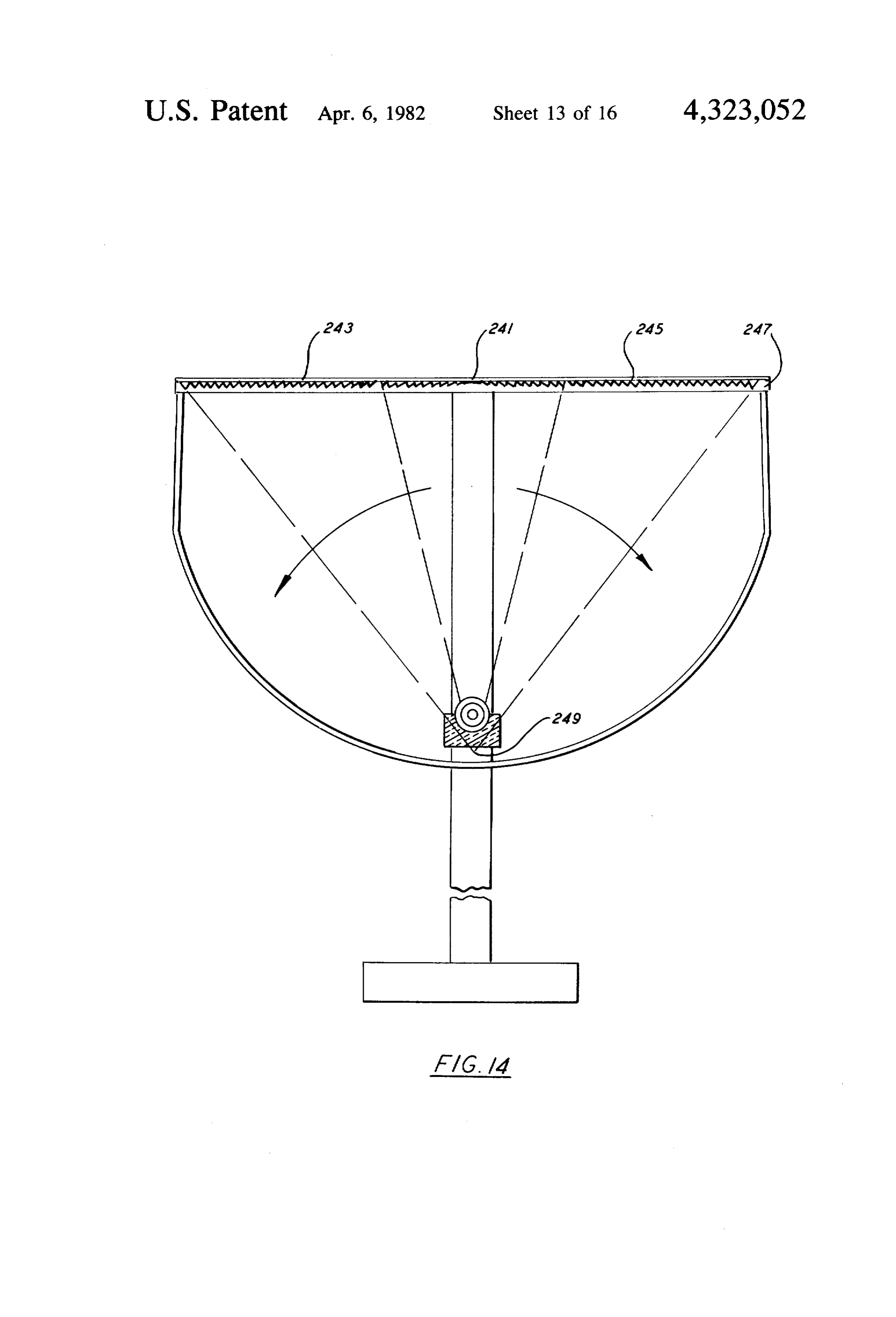
for heat losses which is reduced compared with the two FIG. 13 shows a Fresnel lens with different grooves glass inserted tubes is compensated by a flow of the 25 on the central and side parts in order to have the same second fluid at a controllable higher speed, between the focus track and high concentration ratio. two conduits. The heat losses by convection and radia FIG. 14 shows an array of Fresnel lenses in parallel tion are proportional to the exposed surface of the out with further increase of the aperture in order to obtain side radiation tube so it is of interest to reduce such high concentration.
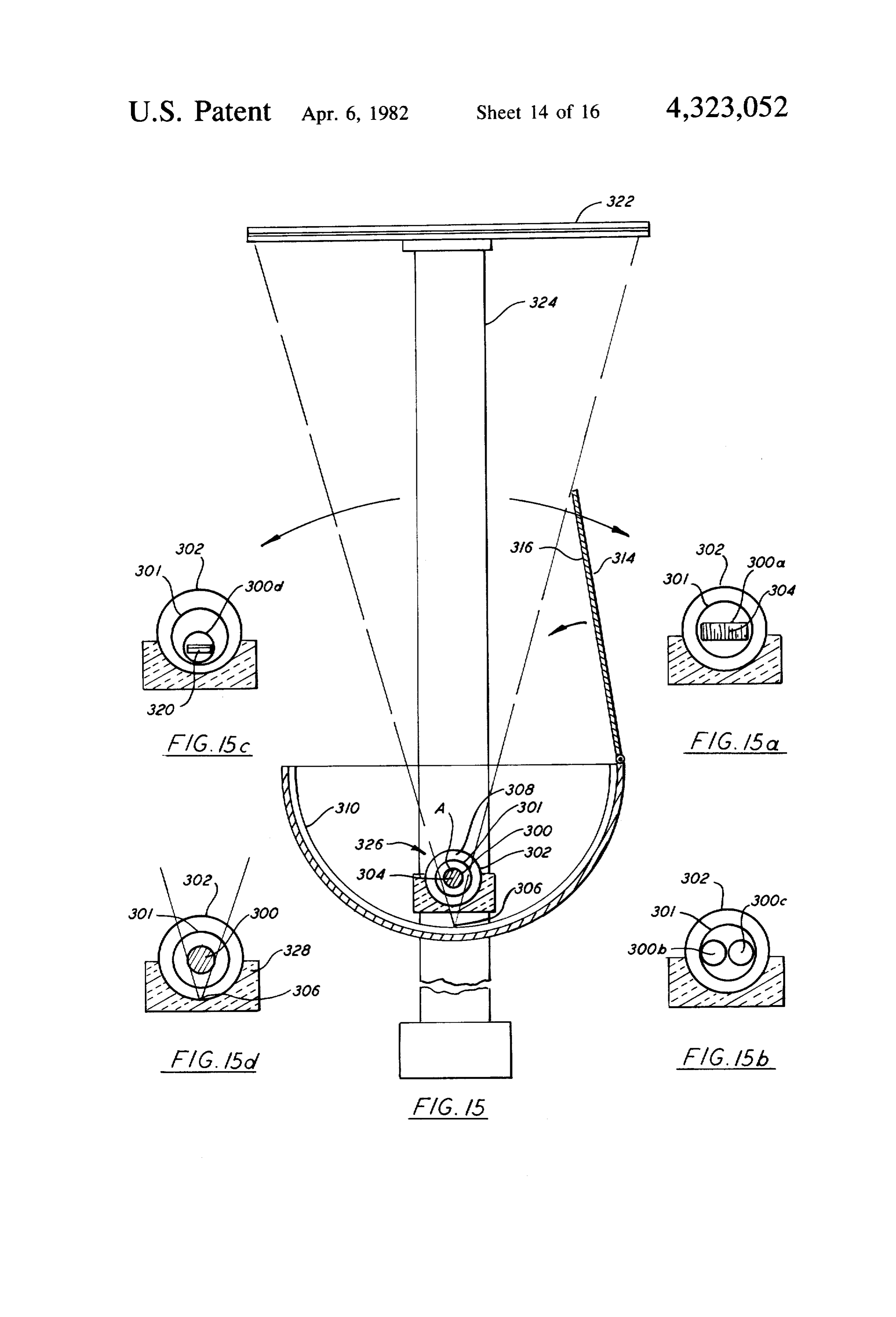
surface, selecting a small diameter for the outside tube, 30 FIG. 15 shows an alternate embodiment with only for example 45 mm OD and by covering the lower part two inserted conduits with two fluids and controlled of such tube with insulation. The radiation losses are circulation in each conduit. proportional with the temperature, that is FIG. 15a is an embodiment similar to FIG. 17 with a rectangular blackened metallic conduit.
35 FIG. 15b is an embodiment similar to FIG. 17 with -(D- two adjacent blackened metallic tubes.
FIG. 15c is an embodiment similar to FIG. 17 but
The temperature of the glass of the outside tube will with a transparent inside glass tube instead of a metallic depend on that temperature of the fluid circulating tube with an array of photovoltaic cells installed in the inside such tube which should be kept preferably at a inside tube and encapsulated in glass or plastic with maximum of 70° C. at its outlet. fluids circulating in the inside and outside tube. FIG. 15d is an embodiment similar to FIG. 17 but
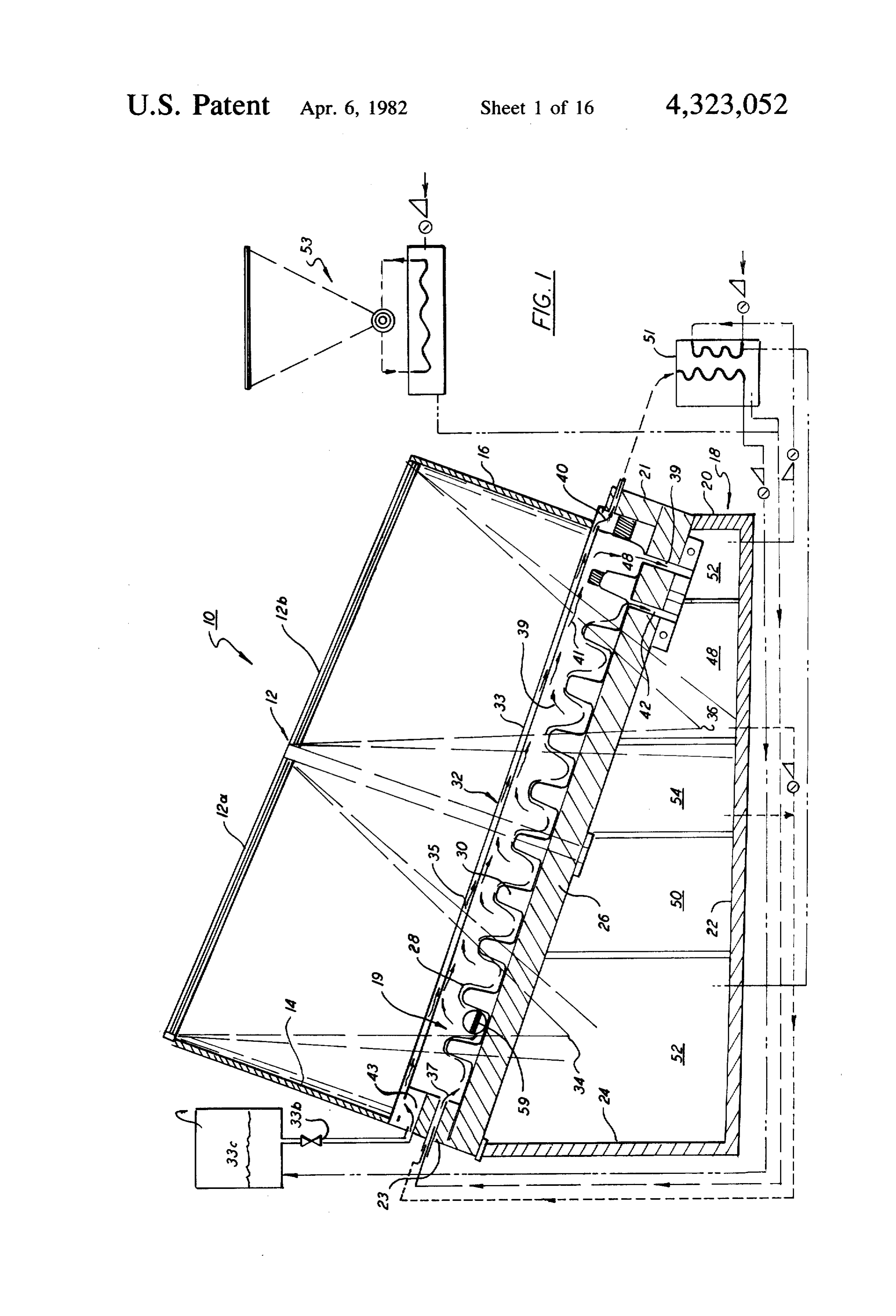
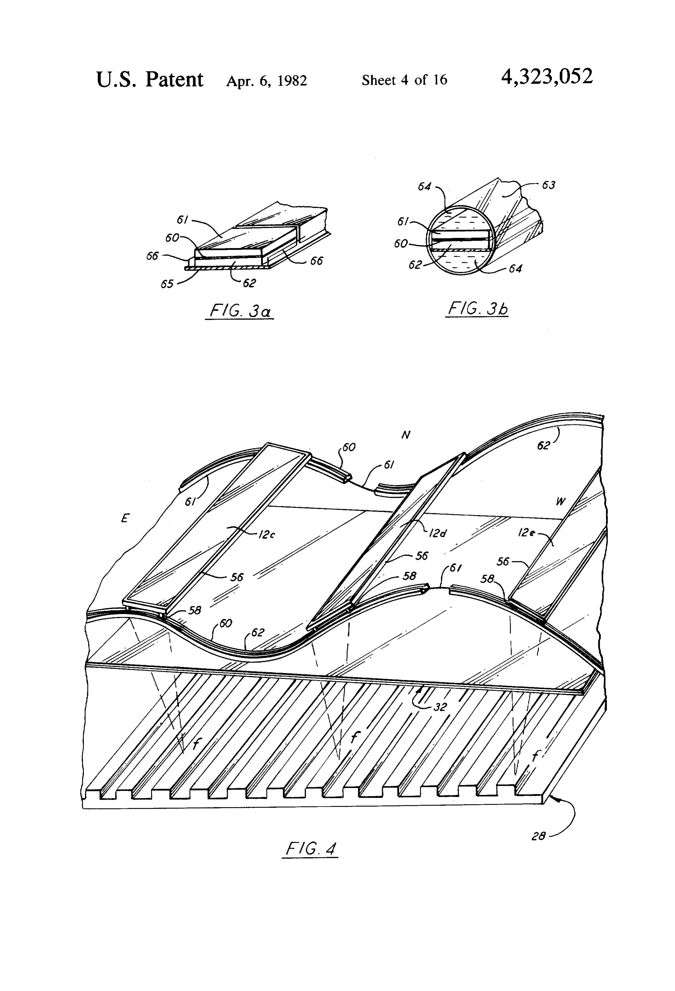
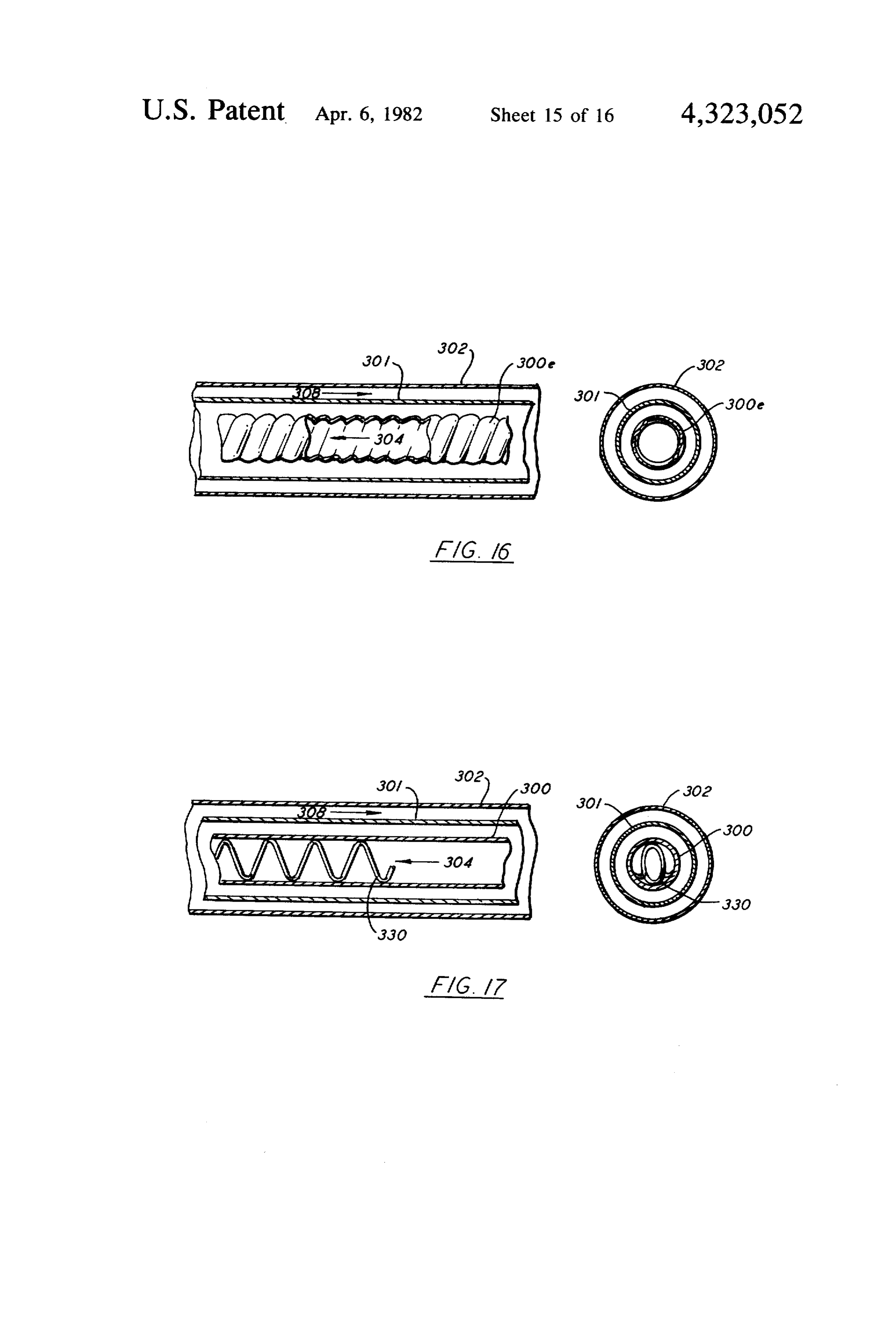
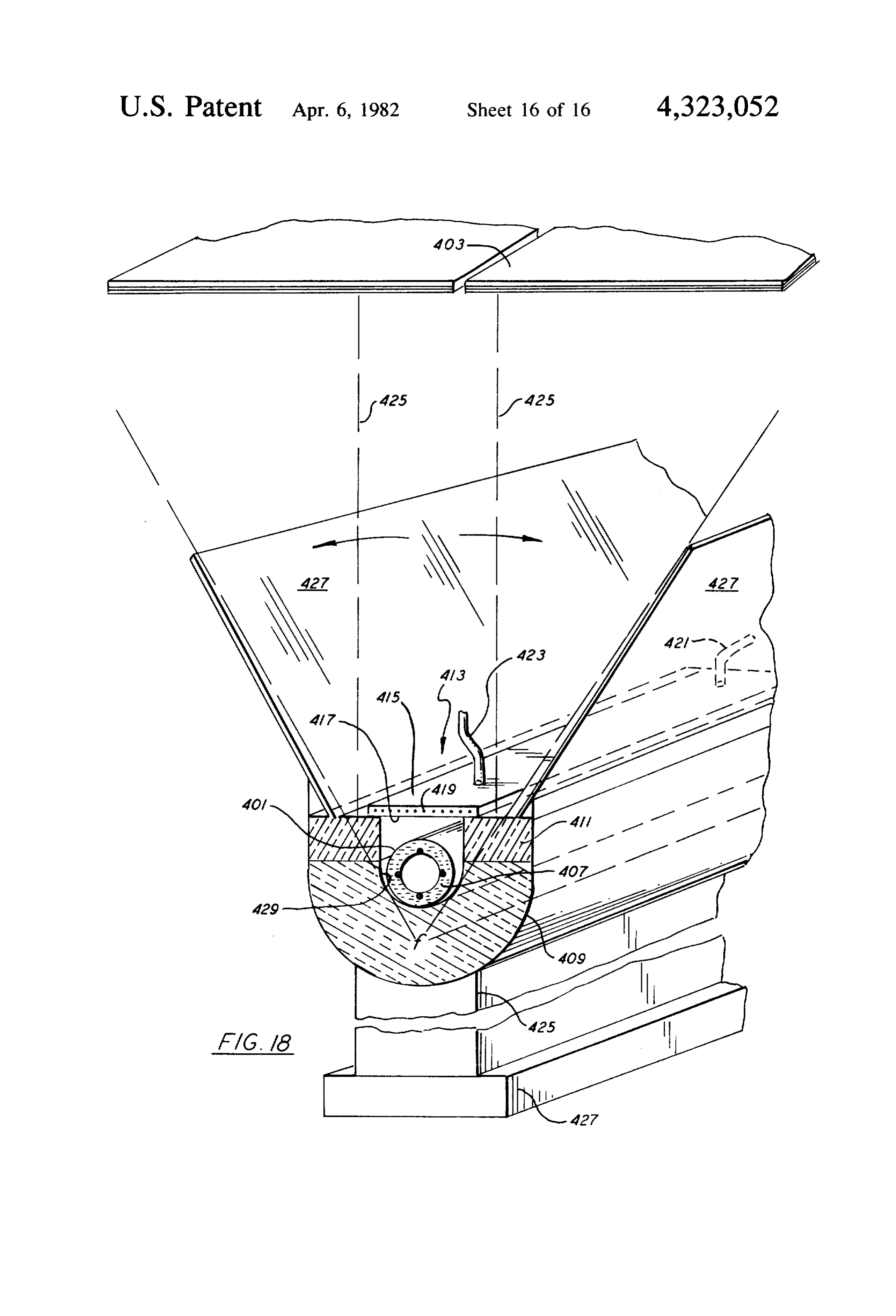
BRIEF DESCRIPTION OF THE DRAWINGS without a mirror below the tube assembly, and instead FIG. 1 is a cross-sectional elevation view through the insulation around the outside of the tube except for an first embodiment of distillation apparatus according to 45 upper part allowing the transmission of the solar rays. the present invention. FIG. 16 is a cross section of a tube similar to that of FIG. 1a is a perspective view of the double plate FIG. 15 in which the inner tube has a corrugated sec system of FIG. 1. tion.
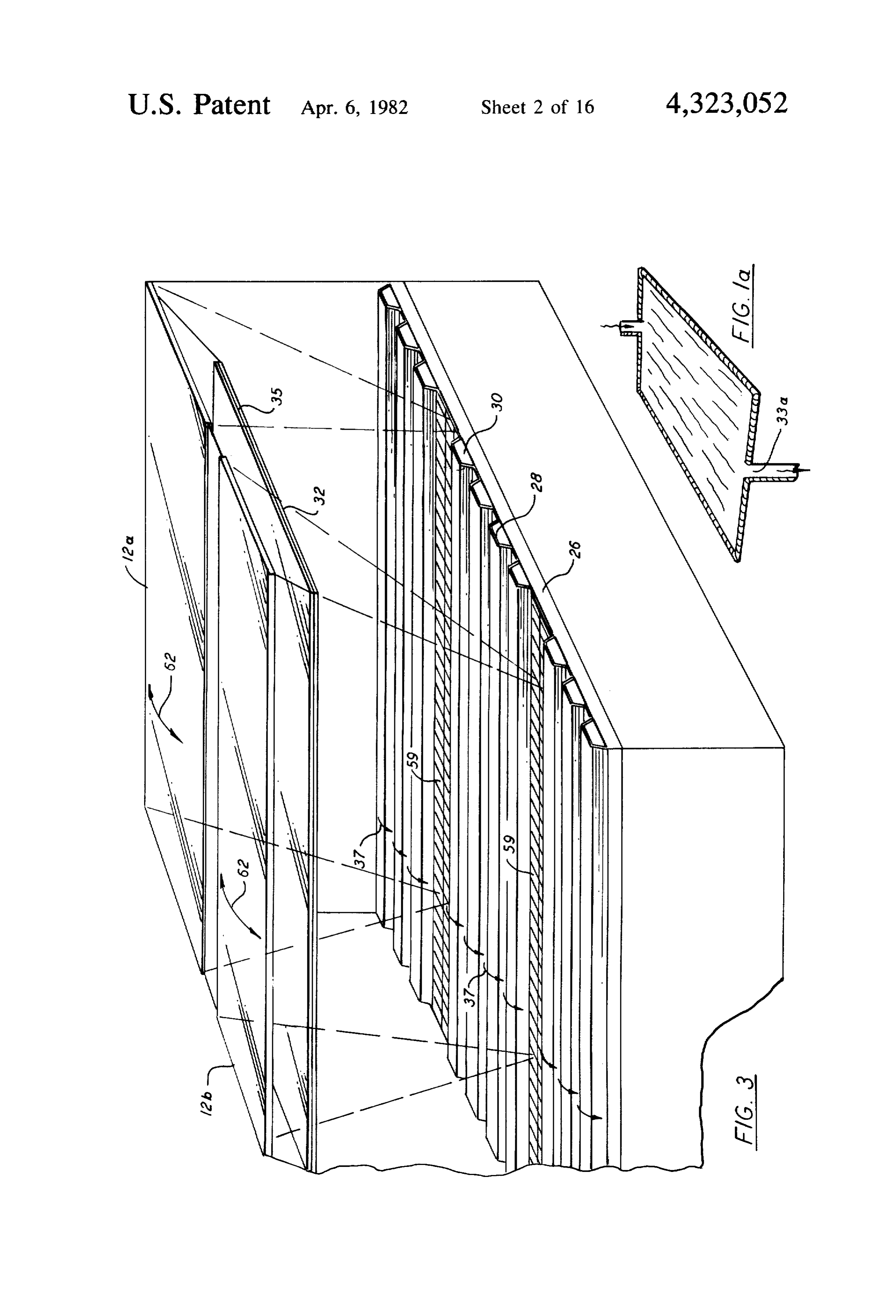
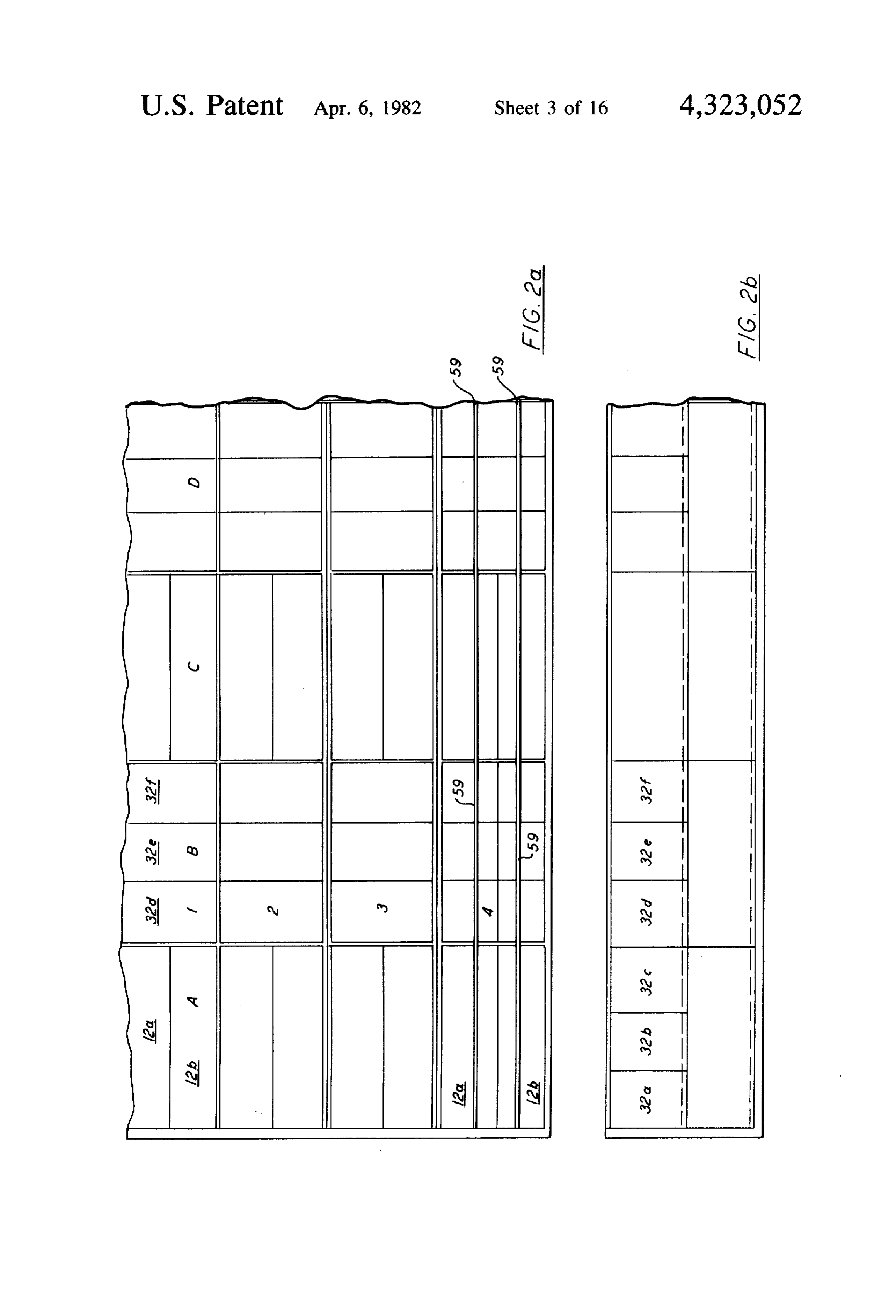
FIG. 2a is a plan view of an installation comprising a FIG. 17 is a similar view in which means to increase plurality of units such as that of FIG. 1. 50 turbulence are inserted inside the inner tube. FIG. 2b is an elevation view of the unit according to FIG. 18 is a perspective schematic view of a further FIG. 1. system according to the present invention using an FIG. 3 is a perspective view of the unit according to insulated tube covered by spaced transparent plates and FIG. 1, showing the installation of photovoltaic cells. enclosed with insulation at its bottom portion. FIGS. 3a and 3b illustrates two solar cell arrange 55 DETAILED DESCRIPTION OF THE ments useful in the embodiments of FIGS. 1-3.
INVENTION
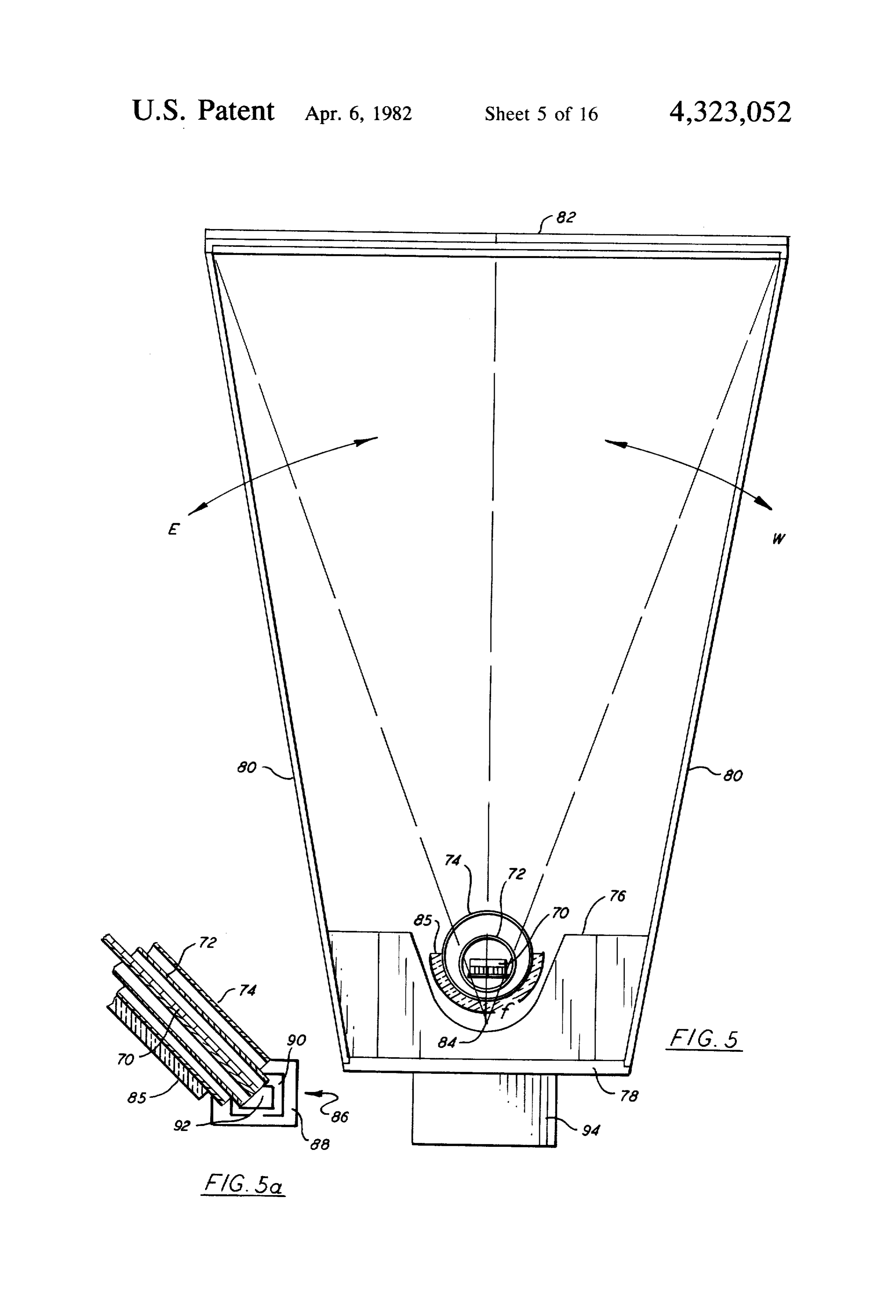
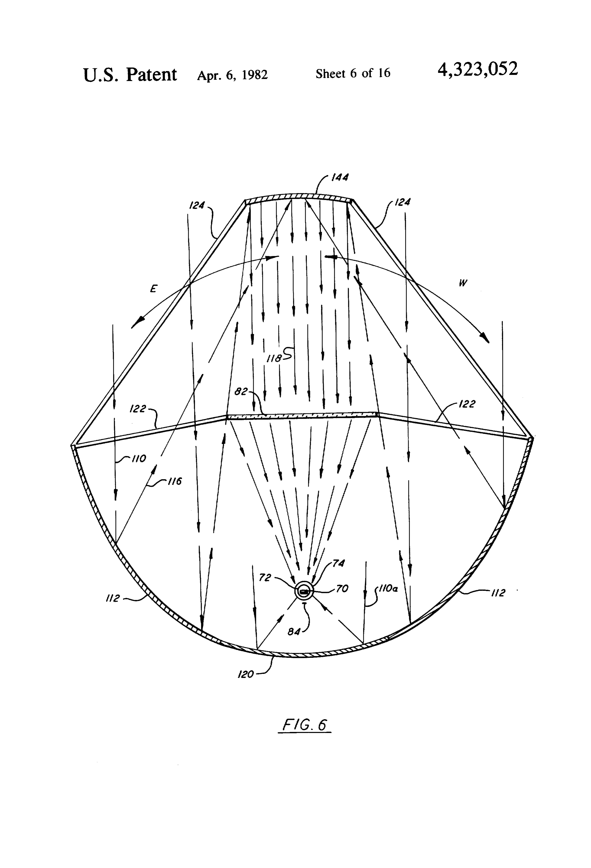
FIG. 4 is a perspective view of an improved system for moving lenses to track the sun. FIG. 1 is a cross-sectional view of solar distillation FIG. 5 is a cross-sectional view in front elevation, of apparatus according to the present invention. The distil embodiment using concentric tubes. 60 lation apparatus 10 of FIG. 1 includes a Fresnel lens FIG. 5a is a side elevation view in cross-section, of system 12 supported on a base structure 18, having a the embodiment of FIG. 5. front wall 20, a bottom wall 22 and a rear wall 24. On FIG. 6 is cross-sectional view of a further embodi the base structure is a container 19 including an insulat ment of the present invention in which mirrors sur ing base plate 26 which rests on walls 20 and 24, a bot rounding a conduit system are utilized for the concen tom end wall 21 and a top end wall 23. The Fresnel lens tration of energy. are supported by supports 14 and 16 which are attached FIG. 7 illustrates a further embodiment of the present to end walls 21 and 23 respectively. The container will, invention utilizing a tube assembly and Fresnel lens of of course, have appropriate side walls, not shown in the
Page 25
figure. On top of this insulating base plate 26 is an undu blackened flexible plastic or the like such as isobutyl can lated plate system 28 which can be made up as a single be used to cover the wall or the bottom plate system system or made up as a plurality of plates. The height of and be attached thereto in a removable manner so that each of the undulations 30 should be, for example, the plastic covering can be taken out and the deposits 90mm (about 3.5 inches). The distance between undula thereon removed. The double plates 31 and 33 are par. tions should be, for example, 120mm (about 5 inches). tially obstructed at the extreme ends (see FIG. 1a) by The Fresnel lens system 12 is tilted to an angle A of, for silicone or other means leaving a small outlet 33a for the example 30 and base plate 26 with the plate system 28 release of the fluid to compartment 40. This is done so thereon tilted, in the illustrated embodiment, to an angle to allow the fluid 35 to spread all over the surface be of 20. In general, this angle A will be selected as de 10 tween the plates 31 and 33. A valve 33b at the upper end scribed in my aforementioned applications Ser. No. of the double plate system 32 permits selectively con 915,001. Interposed between the Fresnel lens 12 and the trolling the flow of the fluid 35. The fluid 35 will flow plate system 28 and parallel to base plate 26 is a double to a collector 43 at the inlet to the double plates 32 from plate conduit 32. In this double plate conduit, having a a tank 33c at a height of, for instance 40cm (about 17') lower plate 31 and upper plate 33, a fluid 35 circulates in 5 above the collector 43 so as to allow a maximum pres the manner described in my aforementioned Ser. No. sure between the plates 31 and 33.
915,001. Salt water 37 which is to be evaporated is As illustrated by FIGS. 2a and 2b, a plurality of units supplied to upper end of the plate system 28 through such as that shown in FIG. 1 can be provided operating end wall 23 and flows downward over the undulations in series and/or in parallel. Furthermore, the Fresnel 30. In the process, heat from the sun which is concen 20 lenses can be arranged so as to run both east-west and trated by the Fresnel lens system, which in the illus north-south. In the embodiment of FIG. 1, the linear trated embodiment includes a Fresnel lens 12a and a Fresnel lenses run in a north-south direction. The dou Fresnel lens 12b, evaporates some of the water in salt ble glass plates 32 are shown in FIG. 2a and 2b as 32a, water flowing over the undulations 30. In accordance 32b, 32c, 32d, 32e, 32f They are tilted east-west, with the present invention in order to spread the solar 25 whereas the Fresnel lenses are oriented north-south. energy over a larger area, the focal points of the Fresnel In accordance with another feature of the embodi lenses 12a and 12b designated as points 34 and 36, re ment of FIG. 1, storage areas are located beneath the spectively, are located below the insulating base 26. insulating plate 26. Shown is a storage area 48 for brine Typically, for example, if the focal distance of the lens 42, a storage area 50 for the fluid 35 circulated in the is 105mm 42 inches), i.e., where there is a distance of 42 30 double plate conduit 32, a storage area 52 for the con inches from the lens to the maximum area of concentra densate 41 and a storage area 54 for concentrated brine. tion, the plates will preferably be located at, for exam By storing the various fluids beneath the insulating base, ple, 90cm (35.5 inches) from the lens. The evaporated further insulation and retention of heat within the sys water vapor 39 which will typically be about 75° C. tem is obtained. Circulation of the various fluids can be rises and is condensed on the bottom plate 31 of conduit 35 carried out in the manner described in my aforemen 32 which contains a fluid 35 typically at 30° C. The tioned application Ser. No. 915,001, and furthermore, as condensate 41 runs down the inside of the plate and is described above. Basically, the fluid collected in the collected in a compartment 38 from which it flows compartment 40 which normally starts out at 30° C. and through an opening 39 to a compartment 52. The fluid is then heated up to approximately 65 C. by the vapor 35 flowing between the plates 31 and 33 of the conduit 40 at 75° C. is circulated to a heat exchanger 51 where it 32 is collected in a compartment 40. Brine 43 which transfers heat to the incoming salt water and in the results from the evaporation of the water from the salt process is cooled back down to 30° C. It is then recircu water flows through an outlet 42 of the plate system 28 lated to a container 33c and flows through value 33b through plate 26 to a compartment 48. entering the double plate system through end wall 23. The plates of the plate system 28 are preferably made 45 Condensate from compartment 52 can also be circulated out of metal such as steel, stainless steel or copper, through heat exchanger 51. In addition, recirculation of having a thickness of, for example, 1 mm. It is preferred the brine for concentration thereof and removal of addi that they be covered by a black paint or chrome black. tional heat therefrom in the manner described above The paint or other agent used should be of an anti-cor may be carried out as shown. Salt water from heat rosive material and provision should be made, if neces 50 exchanger 51 along with additional preheated saltwater sary, to provide cathodic protection for the metal struc from another solar system 53, such as that of my previ ture to prevent the damage which could result from ous application or as described below, enters plate sys electrical currents caused by the reaction between the ten 28 through opening in end wall 23. metal surfaces and existing chemicals in an electrolytic FIG. 3 is a perspective view of a system such as that Solution in the water, 55 shown in the FIGS. 1 and 2. Once again, the insulating As an alternative to metal, undulated asbestos fiber, base26 is shown as is the plate system 28 with its undu glass or plastic plates can be used. Metallic undulated lations 30. The two Fresnel lenses 12a and 12b are plates are preferred since they will conduct heat to all shown as is the double plate conduit 32. However, in sides of the plates, from the location of the striking solar this embodiment, at the bottom of the plate system rays in the focal area. 60 above the points 34 and 36 where the solar energy is As the water being distilled flows over the undula concentrated (see FIG. 1), there are installed arrays of tions, it will be in cavities which are only about 90mm photovoltaic cells 59. Photovoltaic cells 59 produce deep. The thinness of the water in the cavities between electricity from the visible solar rays only, i.e., those the undulations 30, coupled with the thin layer of water form 0.4 to 0.8 microns. The infrared rays will be which flows over the undulations 30 will result in fast 65 mostly absorbed by the fluid flowing in the double plate heating and evaporation of the water. system 32 and by the water being distilled which circu Since deposits can form on the plate system 28, a lates above and around the photovoltaic cells. By using single panel or plurality of adjacent panels made of such an arrangement a separate photovoltaic cell instal
Page 26
lation in order to produce electricity is not necessary. move together. The system is driven such that from Furthermore, because of the concentration of the solar sunrise to sunset the rays of the sun will always be essen energy by the lenses, a production of electricity up to, tially perpendicular to the Fresnel lens. At the end of for instance, twenty times that can only be produced the day, after the sun sets, the lenses can be driven back with concentration. For example, the average yearly to their morning starting position in response to an production of electricity may be increased to about appropriate command.
three watts per cell with the concentration as compared The track system offers a number of advantages. The with about 0.06 Watt per cell without concentration. weight which must be moved is much less than that This arrangement offers many advantages since it which must be moved in rotating a lens and supporting allows concentrating the energy on the cell and, at the 10 structure, in systems such as those disclosed in my same time, removing infrared energy, which would aforementioned Ser. No. 920,288. However, such sys otherwise heat up the cell and reduce its efficiency. The tems can also be used for rotating the Fresnel lenses infrared energy is absorbed by the water 37 being dis used in the present invention. Such is, for example, tilled and by the fluid 35 in the dual plate conduit 32 and illustrated diagrammatically by the arrows 62 of FIG. 3. the distilled water around the cells circulating in the 15 Tracking is preferably done only for the elevation tube enclosing the cells are shown herein, whereas the about the north-south axis. Deviations for seasonal loca visible light is utilized to generate electricity. Thus, tions of the sun which is a maximun angle of 23.5 from simply for the additional cost of the cells themselves, a equinox to solstice will be on each side of the central system which is both a distilling and an electrical gener axis of the focal line without the elevation tracking. The ating unit is provided. Without such cooling, the ten 20 seasonal changes will be along the axis of the focal line perature would be higher reducing the efficiency of the with elevation tracking provided. In the case of FIG. 3, silicon voltaic cells and if the temperature exceeded the lenses will be rotated about the focal point. Again, 200° C., the efficiency would drop to 0 and the cells this can be done in accordance with my aforementioned could melt. Ser. No. 920,288.
The array of photovoltaic cells can be installed in a 25 FIG. 5 illustrates another embodiment of the present transparent square encapsulate protecting the cells from invention. Photovoltaic cells 70 are installed inside a the saline water and over and above which saline water transparent glass or plastic tube 72 which is inserted in is circulated. FIG. 3a shows a photovoltaic cell 60 with another transparent glass or plastic tube 74. Salt water a sub base 62, and an encapsulation 61, board 65 and or brine flows over and around the array of photovol interconnet line 66. The photovoltaic cells can also be taic cells 70. The vapor evaporated from the circulating installed in a transparent glass tube in which a fluid such distilling water or brine 69 will condense on the inside as distilled water is circulated to cool the cells. FIG. 3b wall of the inside tube 72, and the condensate will flow shows a design with photovoltaic cells 60, sub base 62 along such wall and will be collected in the compart and surrounding transparent tube 63 and cooling fluid ment 90 (FIG. 5a). The tubes 72 and 74 are supported 64. This fluid 64 will preferably be the condensate of the 35 above a support 76 containing a cutout of somewhat distilling unit, i.e., the condensate which is collected in semi-circular shape much in the manner of the similar compartment 38 after it has given up its heat in a heat arrangement disclosed in the aforementioned Ser. No. exchanger for preheating the water being distilled. In 920,288. Member 76 rests on a base 78 from which ex this manner, the temperature of the condensate can be tend side supports 80. The supports 80 support a Fresnel reduced from about 75" to about 30° C. This offers a or fluid lens 82. The space between the tubes 72 and 74 number of advantages in that it prevents heated salt contains a fluid similar to the fluid contained in the water from flowing around the photovoltaic cells and double plate conduit of the previous embodiments. In a with the attendant deposits and corrosion which could similar fashion, this fluid acts to aid in condensing the occur. In addition, by having the temperature at 30 vapor which is evaporated from the salt water and instead of 75 C., more efficient production is obtained. 45 brine. Furthermore, along the salt water in the inner For example, with every 1 C. increase in temperature tube, it acts to absorb the infrared radiation to maintain there is approximately 0.4% decrease in electricity pro the photovoltaic cells 70 cooled. As in the previous duction for temperature above 30° C. Thus, by encapsu embodiments, the focal point 84 of the Fresnel lens 82 is lating the cells and cooling them with condensate the located below the photovoltaic cells 70 so that the radi efficiency is increased and the deposit of salts and corro 50 ation is spread thereover.
sion of the cells is prevented. FIG. 5a a cross-sectional elevation view of the tube FIG. 4 illustrates another embodiment of the present system utilized in FIG. 5. The system is preferably tilted invention. In this embodiment, once again the undulated at an angle depending upon the latitude of location. plate system 28 is visible as is the dual plate conduit 32. Also shown in this view is a collector arrangement 86. In this arrangement, the Fresnel lenses, of which three 55 The collector arrangement is divided into three com positions 12c, 12d and 12e are shown, is somewhat dif partments. An outer compartment 88 receives the fluid ferent. The Fresnel lenses are contained in frames 56 which is flowing between the tubes 72 and 74 for recir preferably of a metal such as anodized aluminum. culation in the manner described above. The condensate Mounted at each corner of each frame 56 is a rolling is directed into a middle chamber 90, and brine directed means 58, e.g. a wheel, ballbearing track or the like, 60 into an inner chamber 92. The fluid in the space be which rides in a respective track 60. The tracks have a tween the tubes absorbs the infrared radiation as does sinusoidal shape which is determined by the specific the salt water being evaporated. But visible radiation is latitude location at which the unit is to be used. The used to generate the electricity, since it is this radiation tracks 60 run in a east-west direction. The frames are in the range of 0.4 to 0.8 microns which produces elec preferably connected together by a cable system 61 tricity. The fluid between the glass tubes 72 and 74 as pulling in both directions and the cable to be driven by shown in FIG. 3b absorb the infrared solar rays and a motor activated by a cnetral sensor system. In this heats the circulating fluid which heat is recovered in the way, all of the frames 56 with their Fresnel lenses will same manner described above.
Page 27
The tube assembly is stationary with the remainder of beneficial since it will increase the absorption of infra the structure supported for rotation about the axis of the red radiation, i.e., the fluid in the lenses will act as fur inner tube. Again, this can be done in the manner de ther absorber for infrared radiation. scribed in my aforementioned Ser, No. 920,288. To A further embodiment of the present invention is reduce the forces required for rotation, a counterweight illustrated in FIG. 7. This embodiment is in many ways 94 is provided and attached to the base 78 of the struc similar to the embodiment of FIG. 5. However, in the ture. The moments are selected so that the weight of the embodiment of FIG. 7 a particularly large Fresnel lens counterweight 94 times its distance from the axis or 150, e.g., of an aperture up to 150mm is utilized to heat rotation is approximately equal to the weight of the fluids in a tube assembly 152. Beneath the tube assembly Fresnel lens and its supporting structure times its dis O is a semicylindrical or parabolic structure 154 having a tance from the axis of rotation. As indicated above the mirrored surface 156. The mirror can be made of metal counterweight 94 can be either a steel bar or a container or glass or plastic and covered on its inside surface with filled with a heavy low cost material such as sand or aluminum sheeting, or aluminized, or back silvered concrete. glass, or made reflective by other means. The focal area A plurality of units of this nature can be mounted in 5 of the Fresnel lens 150, designated as 158 is below the parallel and rotated by central sensing means and a structure 154. The structure 154 is continued as, or common electrical motor as previously described. This attached to, supports 160 for the Fresnel lens. Because arrangement, as did the previously described arrange of the large size of the Fresnel lens 150, not all of the ments, permits the distillation of water to be combined radiation focused thereby is directed on the tube assem with the production of electricity of photovoltaic cells bly 152. Some of the radiation falls alongside the tube without the need of the plate system described above, assembly 152. This radiation is then reflected by the but simply through the use of a tube system. mirrored surface 156 back onto the tube assembly 152. A further embodiment of the present invention is In addition, rays of the sun outside of the Fresnel lens illustrated in FIG. 6. In the embodiment therein, a tube will also strike the mirror 156 and be reflected. The tube system having an outer tube 74, inner tube 72 and possi 25 structure 152 includes an outer tube 162, an intermedi bly a photovoltaic cell array 70, much in the manner of ate tube 164 and an inner tube 166. A fluid 168 can flow that shown in FIG. 5 is used. Once again, disposed in the inner tube with a fluid 170 flowing in between the above the tube system is a Fresnel lens 82. And again, it outer and intermediate tubes 162 and 164. With this type is arranged so that its focal area is below the tube system of an arrangement, the fluid 168 can be heated up to a in order to spread the radiation over a larger area. How 30 temperature of, for example 300° C. The fluid 170 will ever, in this embodiment a plurality of mirrors are used be circulated and maintained at a temperature of, for to further concentrate the energy. With this embodi example 75 C., so as to limit the heat losses from the ment, incoming solar rays 110 are reflected from curved fluid 168 and also to absorb additional energy which is mirrors 112 which are to the side of and, below the reflected within the tube assembly 152. The inner tube Fresnel lens 82. Installed directly above the Fresnel lens 35 can be made out of metal preferably blackened by elec is a mirror 114. The mirror 114 is shaped so as to colli troplating with a fluid circulating inside the metallic mate light. The collimated light 118 then impinges on tube, the focus target will be on the surface of the metal the Fresnel lens 82 which focuses it in the manner de lic tube. The metallic tube will be surrounded at a se scribed above. lected distance of, for instance 2mm by a transparent Directly below the tube system is a further mirror 120 40 glass tube. A fluid will be circulated between the two or the same extended mirror 112 which directs addi glass tubes at a selected rate. The metal heated by the tional incoming solar energy 110a onto the bottom por concentrated solar energy will heat with a high emissiv tion of the tube 74 to collect further amounts of energy. ity of the order of over 90%, the fluid circulating inside The mirrors 112 and 120 will, of course, be supported in the metallic tube. The air cushion will act as insulation, conventional fashion. Supports 112 of the Fresnel lens 45 forming a heat barrier for the convection losses to and supports 124 for the mirror 114 are also shown. gether with the two glass tubes, and especially through The system of FIG. 6 is supported to track the move absorption of heat by the fluid circulating between the ment of the sun. As with previously described systems, two glass tubes with control of the circulating rate. The the axis of rotation is the central axis of the inner tube radiant heat emitted by the metallic tube with less than 72. The tube system itself will remain fixed so rotation 50 10% radiation will also mostly be absorbed by the can be carried out in the manner described above and in above heat barriers. All of above will insure low heat the aforementioned Ser. No. 920,288, losses and high efficiency of the system. As with my The system of FIG. 6 can substantially increase the previously described embodiments, the structure corn received radiation since the surface of the mirrors 112 is prising the member 154, supports 160, and Fresnel lens larger than the Fresnel lens 82. The concentration of 55 150 will be supported for rotation as indicated by ar solar energy at the focus area 84 will be much higher rows 72. As in the previous embodiments, rotation will when one considers the larger proportion between the be about the axis of the inner tube of the tube assembly surface of the mirrors 112 and 120 and the surface of the 152 and will be used for tracking the sun. In addition, focus 84. Thus, this embodiment is particularly applica the assembly can also be mounted to track seasonal ble to the production of electricity which increases changes, i.e., be mounted for movement both in azimuth almost proportionately with concentration. As in the and elevation. In addition to its use as a system for previous embodiments, the infrared rays will be ab heating a fluid, the system can also be used for distilla sorbed by fluids both between the tubes 72 and 74 and tion and for the production of solar energy. Thus, the the fluid within the tube 72. inner tube 166 may comprise the encapsulation for solar As with any of the aforedescribed embodiments, a 65 cells 174 in which a cooling fluid such as distilled water fluid lens may be provided instead of a Fresnel lens. In is circulating in the manner described above. The space this embodiment in particular, when used for electricity between the inner tube and intermediate tube 164 can production from photovoltaic cells, a fluid lens may be contain water to be evaporated, and the space between
Page 28
the outer tube 162 and the intermediate tube 164, a system 204 (see FIG. 11) with mirrors 191 and support cooling fluid for condensing the evaporated water, 194 and a counterweight 199 for balance. The tube much in the manner disclosed in connection with FIG. assemblies 193 remain stationary. The E-W movement 5. Of course, this embodiment can be used for the pro of the supports 194 is linked by linkages 214 and 216 so duction of electrical energy with photovoltaic cells as to cause a linear movement of piston 218 provided alone, or may be used for distillation alone as can the with at least one orifice 220 moving in a cylinder 222 embodiment of FIG. 5. filled with a fluid 224 in chambers 226 and 228 on oppo FIG. 8 shows another embodiment of the invention. site sides of piston 218. Fluid is pushed through the It provides reflective parabolic longitudinal mirrors 161 narrow orifice 220 from chamber 226 to the chamber of adequate shape, preferably made of thin waterwhite O 228 as the lenses rotate from East to West. In the case of glass or similar reflective material. Solar rays will be a wind gust, the flow of the fluid from the one chamber reflected on one or more tube assemblies 162, 163 and to the other will be slowed by the passage through the 164, inserted in each other. Fluid 165 will circulate in narrow orifice 220. They will act as a brake and slow the inside tube. Also a fluid 166 will circulate between down any rotating movement of the Fresnel system. the outside tube and the intermediate tube inserted in it. 15 The fluid from the one chamber such as 226 may flow Photovoltaic cells and or distillation of water can be through a special pressure relief valve 230 into another provided as shown in FIGS. 5, 8 and 9 above. cylinder 232. This will allow the Fresnel system to drop The design as shown in FIG. 8 does not require a to the initial East position of the morning or to the concentrating lens. The tube assembly will be oriented extreme West position and then reverse to its initial East-West and no tracking may be required since the morning position. The electric motor will be stopped solar rays from East and West will be reflected on the after the Fresnel system is dropped to its initial morning tube assembly. position and thus the worm gear 200 will discontinue FIG. 9 shows a tracking system similar to the one moving the Fresnel system.
shown on FIG. 4. The Fresnel lenses 56 with their After the wind gust is over and for normal continua frames 12d are pulled East-West along the sinusoidal 25 tion of operation, the fluid will be pumped by a piston stationary railing 61 to follow the location of the Sun 234 into the cylinder 222. This can be done either manu during the day. In the evening they are pulled back to ally or automatically by acting on the piston 234. the initial morning position. The Fresnel lenses are A series of Fresnel lens units can be coupled together moved in the direction of their longitudinal side (244 and to the shock absorber of FIG. 12 for absorption of cm) providing a continuous heating of the circulating 30 the shock by high winds or gusts.
fluids in the collector assembly 180. The collector tube FIG. 13 shows a Fresnel lens 225 with three sections, assembly 180 together with the surrounding reflecting a central section 227 and side sections 229 and 231 with mirror 182 around its bottom surface are stationary. The different grooves allowing all solar rays for each of the focal line will be on or under the tube assembly. The positions to focus on the same focus line 233 preferably inside tube of the tube assembly can be a blackened 35 under a tube assembly 235. A reflective mirror 237 is metallic tube. In case encapsulated photovoltaic cells installed beneath the tube assembly. Mirror 237 has a are installed in the inside tube such tube will be of glass large aperture, similar to the one of the Fresnel lens. or plastic (see FIGS. 15-15c). The Fresnel lenses 56 can A counterweight 239 is provided, with the entire be adjacently installed in the same frame or combined system supported for rotation around the axis of the frames with only a control cable 184 provided for mov 40 inside tube in stationary tube assembly 235. ing them. FIG. 14 shows a system similar to that of FIG. 13. This arrangement permits selected stationary collec However, in this embodiment, three large Fresnel tors of selected length to be utilized especially when lenses 241, 243 and 245 are adjacently installed in paral metallic tubes with easy interconnection are considered. lel in the same frame 247. Lenses 241, 243 and 245 have FIG. 10 provides a similar tracking system. However, 45 proper grooves for focusing in the same focus track 249 the Fresnel lenses 56 are moved in the direction of their with similar tracking as in FIG. 15. The systems de width (84 cm) instead of their length as in the previous scribed in the aforementioned application No. 807,513 case. Several Fresnel lenses can be installed in the same showing separate lateral Fresnel lenses inclined to avoid or adjacent frames and moved together on two or more the elevation and seasonal tracking of the system may railings. Parallel stationary tube assembly collectors 180 50 also be applied to the lens systems of FIGS. 13 and 14. with surrounding reflective mirrors 182 around their FIG. 15 shows an alternate embodiment to the previous bottoms are provided; photovoltaic cell arrays can be disclosures utilizing two conduits inserted in each other installed. instead of three conduits. The inside tube 300 is a metal The Fresnel lenses can be provided only in parallel or lic conduit blackened on the outside surface with a in series and parallel or singly. 55 material corrosion resistant to the fluid flowing around FIG. 11 illustrates an embodiment in which two Fres it. The outside conduit 302 is transparent, preferably nel lenses 190 and 192 are supported in a common frame Pyrex glass.
194 adapted for rotation by means of a ring gear 196 A fluid 304 with a boiling point of over 300° C. flows driven by a worm gear 198. As in other embodiments a with controlled circulation in the inside tube 300 and is counterweight 199 is provided. An aluminized mirror 60 heated by solar energy with a focus 306 on or under this 191 is provided below each of two tube assemblies 193 tube 300. A fluid 308 circulates with controlled flow similar to the embodiment of FIG. 9. Also installed are rate between the conduits 300 and 302. protective flaps 195 adapted to be lowered if a predeter A reflective aluminized mirror 310 is installed below mined temperature or pressure is exceeded in tube as the tube assembly and backed by insulating material Semblies 193. 65 312. The mirror will reflect scattered solar rays from FIG. 12 shows an absorbing device for absorbing the the Fresnel lenses and direct rays into the tube assembly shock of a wind gust, for example. A stationary worm and increase the solar energy collection and concentra gear 200 rotates a disk 202 which drives a Fresnel lens tion. A security panel 314 aluminized on one surface 316
Page 29
will be provided and will drop automatically on the These provisions can also be used for other applications collector in case of overpressure or overtemperature at of the solar system.
selected levels in order to prevent further solar heating Another embodiment of the present invention is illus in such accidental cases. A counterweight 318 is at trated by FIG. 18. In this embodiment, energy is col tached by the supports 320 at each end of the unit. lected primarily within the tube 401 onto which con The Fresnel lens 322 with a frame 324, the supports centrated solar energy collected by a Fresnel lens 403 is 320, the mirror 310 and the counterweight 318 rotates directed. The tube 401, assuming it is to perform the from East to West around the axis (A) of the inside tube function of heating a circulating fluid such as Ther 300 to track the elevation position of the sun. The tube minol, will preferably be a metal tube with its outside assembly 326 will remain stationary. A reversing elec O surface darkened by electroplating, preferably with tric motor brings the rotating system to the initial morn chrome black. Shown in the embodiment of FIG. 18, ing location by contacting a limit switch. within the tube 401 is another metalic tube 405 contain Instead of one, several Fresnel lenses can be provided ing rings or other means to obtain a turbulant flow of with proper grooves in order to allow the concentration the fluid 407 which is to be heated. The lower portion of in one common focus track. 15 the tube 401 is surrounded by insulation 409. A cover FIG. 15a shows a similar arrangement with a rectan structure 411, the side portions of which are preferably gular blackened metallic conduit 300a instead of round; transparent, supports a double plate system 413, which this will allow a larger focus track. includes an upper plate 415 and a lower plate 417 above FIG. 15b shows a similar arrangement but with two tube 401. The sides of the plate are sealed in the manner adjacent round blackened metallic conduits 300b and 20 described above in connection with FIG. 1a. A second 300c inserted in the outside conduit. fluid 419 is circulated between the plates 415 and 417, FIG. 15c shows a similar arrangement in which the there being provided an inlet 421 and an outlet 423 inside tube 300d is transparent and an array 320 of pho connected to flexible tubing, for example, for this pur tovoltaic cells encapsulated in glass, plastic or similar pose. As in previously described embodiments there are material is installed in the inside tube 300d with fluid 25 supports 425 supporting the Fresnel lens 403 above the circulating in both tubes. tube 401. These supports 425, in addition, support the FIG. 15d shows a similar arrangement but without a insulation 409 and cover 411 with the plate assembly reflective mirror and with insulation 328 around the 413 thereon. The supports 425 extend below the insula outside conduit 302 except for the upper part allowing tion 409 and there is attached a counter weight 427 in transmission of solar rays to the focus 306. The insulat 30 the manner previously described. Also illustrated are ing unit and tube assembly will be stationary whereas reflective panels 427 angled upward from the cover 411. the other items are rotating as shown above. Reflective panels 427 can be made of aluminum and FIG. 6 shows an additional embodiment of the pres silvered on their surface. In the preferred embodiment ent invention in which a metallic inside conduit 300e all elements of the system, except for the pipe 401 and preferably has corrugated sections so as to cause turbu 35 whatever pipe is inside it, rotate to follow the sun. As in lent flow of the fluid 304. The inside conduit 300e will previously described embodiments, rotation is about the preferably be 20 mm OD. Its outside surface will be axis of the pipe 401. In view of this, the insulation 409 is darkened by electroplating preferably with chrome preferably of light foam to aid in permitting ease of black in order to have an emission of radiation of less rotation about the tube 401. In addition, it is preferred than 10% and an absorbance factor of 90%. 40 that a reflective paper 429 such as aluminum foil be The corrugated section can be welded on both sides disposed between the insulation and the pipe 401. Fur of the conduits before electroplating. thermore, it is preferred that the reflective panels 427 be FIG. 17 illustrates another manner of obtaining tur rotatable to act as protective safety shields much in the bulence of circulation to increase the heat exchange. In manner of the panels 195 of FIG. 11 to block the solar this embodiment, in the inside of the conduit 300, means 45 energy if impermissible temperatures are reached such as springs 330 are introduced which will cause within the pipe 401.
turbulence 330 of fluid 304 without affecting the circu In operation, solar energy is focused by the Fresnel lation of the outside fluid 308 thus not increasing the lens 403 on a focus located in or below the pipe 401. heat exchange with the ambient. Scattered energy is reflected by the reflective panels The irradiation on the collecting surface of the lenses 50 427 onto this area. Typically, the double plate 413 is described above depends not only on the daily position spaced about 10 mm from the tube 401 at its closest of the sun but also on the season and the latitude of the distance. The double plates can have a width of 30 to 60 locations. mm or larger. The positioning of the plates and the fluid The lenses have to be tilted at an optional angle as flowing therein performs a function similar to the fluid compared to a horizontal surface which depends on the 55 flowing between the outer and intermediate tubes in latitude and the season. previously disclosed systems. The space between the The apparatus for distillation of water as shown in double plate system 413 and the tube 401 forms an air FIG. 1, has Fresnel lenses concentrating the solar en insulation space corresponding in function to the air ergy which can be made movable not only for tracking insulation space between the inner and intermediate (E.W.) but also orientable by either manual or auto tubes in previous embodiments. However, particularly matic means so to change the tilting as the seasons in an embodiment utilizing a blackened metal pipe, the change to obtain optimum irradiation, which may vary, present embodiment offers significant advantages, in with the season. that only metal pipe sections need be connected to This orientation of the Fresnel lenses can be made gether as opposed to the requirement in the other em without interference with the rest of the distillation unit 65 bodiments for connection of transparent glass pipes, for since such lenses are installed above the double plates example, which require expansion joints. with tight ends so that the water vapor does not enter At the same time, improved freedom from heat loss is the space between the double plate and the lenses. achieved. The fluid 407 within the tube 401 will be a
Page 30
fluid capable of being heated to a high temperature of What is claimed is:
for example, 200 C., such as Therminol. In such a tube 1. Apparatus for recovering energy from the sun carrying a high temperature fluid there will be heat comprising:
losses due to radiation and convection. The radiation (a) means for conducting a first fluid comprising heat loss, ER in kilowatt hours equals 5 water to be distilled;
(b) linear lens means having a focal length f, said lens means located a distance less than f from said
to , means for conducting and arranged so as to direct concentrated solar energy on said means for con where e is the emissivity factor, S the surface area, and O ducting with the focus of said lens means on or T the absolute temperature at the surface area. The heat below said means for conducting; loss by convection Ee equals fx dt XS, where F is a (c) conduit means transparent to visible light inter factor which depends on wind and varies between 6 and posed between said means for conducting and said 24 for winds between 10 and 25 miles per hour, dt is the 5 lens means;
temperature difference between the surface and the (d) means supplying a second fluid comprising a cool outside air and S is again the surface area. ing fluid to said conduit means for assisting the By providing the insulation 409 around a large por condensation on said conduit means of water evap tion of the tube, heat losses are proportionally reduced orated from said means for conducting; with the reduction of the exposed surface area S. Fur (e) means for collecting the condensed water; and thermore, the heat of radiation and convection are also (f) at least one array of photovoltaic cells disposed in absorbed by the fluid 419 flowing between the plates said means for conducting at a location of the con 415 and 417. This results in the heating of this fluid. In centration of solar energy by said lens means. addition, the insulating effect of the air space below the 2. Apparatus for recovering energy from the sun plate system 413 aids in preventing heat loss. Thus, the 25 comprising:
heat loss will be primarily the heat loss from the upper (a) means for conducting a first fluid comprising plate 415 of the plate system 413. Since the fluid in the water to be distilled, said means for conducting space between these plates is at a lower temperature, for comprising an undulated plate system; example 60° C., the temperature differential dt between (b) linear lens means having a focal length f, said lens the fluid and the ambient air will be much less than it to would be if the pipe 401 was exposed to the ambient air.
means located a distance less than f from said means for conducting and arranged so as to direct
Furthermore, its surface area is smaller than that of the concentrated solar energy on said means for con hotter tube 401. Thus, reduced heat losses are experi ducting with the focus of said lens means on or enced. In the manner described in my previously men below said means for conducting, said lens means tioned co-pending applications and herein, the circula- is comprising at least one linear lens aligned so as to tion of the fluids 419 and 407 should be controlled so as direct its energy onto said plate system; to maintain desired temperatures within the tube 401 (c) conduit means transparent to visible light inter and the plate system 413 respectively, again, typical posed between said means for conducting and said examples are temperatures of 200 C. within the tube lens means, said conduit means comprising a dou 401 and 60° C. in the plate system. 40 ble plate conduit having an upper and a lower plate In addition to the use of a blackened tube 401, the interposed between said linear lens and said undu system can also be adapted for generating electrical lated plate system, energy using photovoltaic cells in which case tube 401 (d) means supplying a cooling fluid comprising dis must be transparent. Whereas in the case of the black tilled water to said conduit means for assisting the ened tube for heating a fluid, such fluid should be some- 45 condensation thereon of water evaporated from thing such as Therminol or a similar fluid, in the case of said means for conducting; and photovoltaic cells distilled water is used. In both cases, (e) means for collecting the condensed water, the first the fluid circulating in the double plate system 413 may fluid conducted over said means for conducting be a mixture of distilled water and glycol. and said cooling fluid.
This system may also be utilized for the distillation of 50 3. Apparatus according to claim 1 and further includ water much in the manner illustrated in connection with ing means encapsulating said array and means supplying FIG. 5 and FIG. 5a, the primary difference being that a cooling fluid around said encapsulating means to cool only a single inner tube is used with the plate system 413 said array.
performing the function of the other tubes. In the case 4. Apparatus according to claim 3 wherein said cool of water distillation and in the case of electrical energy 55 ing fluid comprises distilled water. production from photovoltaic cells, both of which func 5. Apparatus for recovering energy from the sun tions can be combined much in the manner disclosed in comprising:
connection with FIG. 5, the tube 401 will, of course, (a) means for conducting a first fluid comprising have to be a transparent tube, furthermore, in such cases water to be distilled, said means for conducting the inner tube 405 which aids in obtaining a turbulent 60 comprising a first transparent tube; flow for better heat transfer is not used. (b) linear lens means having a focal length f, said lens In addition, the portion of this system including the means located a distance less than f from said tube 401 and whatever is inside, the insulation 409, means for conducting and arranged so as to direct cover 411 and double plate system 413 with or without concentrated solar energy on said means for con panels 427, can instead be installed in a system such as 65 ducting with the focus of said lens means on or that shown in FIGS. 9 and 10, i.e., one in which track below said means for conducting: ing is carried out by moving the Fresnel lenses on a (c) conduit means transparent to visible light inter sinusoidal railing. posed between said means for conducting and said
Page 31
lens means comprising a second transparent tube least part of said plates in a manner such that it is remov surrounding said first transparent tube; able to permit removing deposits therefrom. (d) means supplying a cooling fluid comprising dis 20. Apparatus according to claim 12 or 2 and further tilled water to said second transparent tube, said including means supporting said lenses to track the cooling fluid being circulated between said tubes 5 location of the sun.
for assisting condensation of water being evapo 21, Apparatus according to claim 12 or 2 and further rated on the inside of said first tube; and including at least one array of photovoltaic cells in (e) means for collecting the condensed water, the first stalled in one of the valleys of the undulations in align fluid conducted through said first transparent tube ment with the focal track of one of said lens means. and said cooling fluid. 10 22. Apparatus according to claim 1 wherein said 6. Apparatus according to claim 5 and further includ conduit means comprise a double plate conduit having ing means to cause said lens to track the movement of an upper and lower plate interposed between said lens the sun, said means adapted to rotate said lens about an means and said means for conducting, the longitudinal axis concentric with the axis of said first tube, said lens sides of said plates fully obstructed by a joint, with only being adapted to direct its radiation along said tubes 15 part of the plates obstructed along their width leaving a with its focal point below the bottom of said tube assem small free outlet space so to allow a wide spread of fluid bly.
7. Apparatus according to claim 5 and further includ along 23.
the surface between the plates.
Apparatus for recovering energy from the sun ing an array of photovoltaic cells disposed in said first comprising:
tube. 20 8. Apparatus according to claims 4 or 7 wherein said (a) means for conducting a first fluid; distilled water comprises the cooled condensate ob (b) linear lens means having a focal length f, said lens means located a distance less than f from said tained from said water being distilled. means for conducting and arranged so as to direct 9. Apparatus according to claim 7 and further includ concentrated solar energy on said means for con ing means encapsulating said array and means supplying 25 a cooling fluid around said encapsulating means to cool ducting with the focus of said lens means on or said array. below said means for conducting; 10. Apparatus according to claim 7 and further in (c) conduit means transparent to visible light inter cluding a curved mirrored surface below said tube as posed between said means for conducting and said sembly and means for moving said lens and said mir lens means, said conduit means comprising a dou rored surface together to track the sun, said tube assem ble plate conduit having an upper and lower plate bly remaining fixed. interposed between said lens means and said means 11. Apparatus according to claim 10 and further in for conducting, the longitudinal sides of said plates cluding insulation disposed about the lower part of said fully obstructed by a joint, with only part of the tube assembly. 35 plates being obstructed along their width leaving a 12. Apparatus according to claim 1 wherein small free outlet space so as to allow a widespread (a) said means for conducting comprise an undulated of fluid along the surface between the plates. plate system; 24. Apparatus according to claims 10 or 23 and fur (b) said lens means comprise at least one linear lens ther including a tank filled with said second fluid dis aligned so as to direct its energy onto said plate posed above said conduit so to maintain a constant system; and pressure of about 40 cm of water column between said (c) said conduit means comprise a double plate con double plates.
duit having an upper and a lower plate interposed 25. Apparatus according to claim 1 wherein said between said linear lens and said undulated plate means for conducting a first fluid comprise a tube, said system. 45 conduit means transparent to visible light comprise a 13. Apparatus according to claims 12 or 2 and further pair of spaced plates having an inlet and an outlet, and including an insulating base plate below said plate sys further including insulation surrounding the lower por tenn. tion of said tube; and cover means over said insulation 14. Apparatus according to claims 12 or 2 and further supporting said spaced plates above said tube with an including at least one storage means disposed below 50 air space therebetween.
said insulating plate for storing fluids used in said appa 26. Apparatus for recovering energy from the sun ratus. comprising:
15. Apparatus according to claim 12 or 2 wherein said (a) a tube for conducting a first fluid; plates have an undulation with a depth on the order of (b) insulation surrounding the lower portion of said up to 90 mm and are separated by approximately 120 55 tube;
mm and have a black coating. (c) elongated linear lens means having a focal length 16. Apparatus according to claim 15 wherein said f, said lens means located a distance approximately plate system is made out of metal selected from the equal to f from said tube and arranged so as to group consisting of stainless steel, steel and copper. direct concentrated solar energy on said tube, the 17. Apparatus according to claim 15 wherein said focus of said len means being in or on and substan plate system is covered with a material of anticorrosive tially along said tube;
nature. (d) conduit means transparent to visible light inter 18. Apparatus according to claim 12 or 2 wherein said posed between said tube and said lens means, said plates are made of a material selected from the group conduit means comprising a pair of spaced plates consisting of asbestos fiber, tightened precast concrete, 65 having an inlet and an outlet; glass and plastic. (e) means for supporting said spaced plates above said 19. Apparatus according to claim 12 or 2 and further tube with a space between the tube and the spaced including a blackened flexible material disposed over at plates; and
Page 32
(f) means supplying a second fluid to said conduit group consisting of blackened asbestos cement, water CalS. tight precast concrete, glass and plastic. 27. Apparatus according to claims 25 or 26, and fur 33. Apparatus according to claim 29 and further in ther including a reflective paper between said insulation cluding at least one storage means disposed below said and said tube.
insulating plate for storing fluids used in said apparatus.
34. Apparatus according to claim 29 and further in 28. Apparatus according to claims 25 or 26, wherein cluding means supporting said lenses to track the loca said linear lens means comprises a Fresnel lens and tion of the sun.
further including: 35. Apparatus according to claim 29 and further in (a) a frame for supporting said lens, said insulation, 10 cluding at least one array of photovoltaic cells installed said cover means, and said spaced plates for rota in one of the valleys of the undulations above the focus tion about the axis of said tube; and of one of said lens means.
(b) a counterweight attached to said frame to balance 36. Apparatus for recovering energy from the sun the weight of said Fresnel lens. comprising:
29. Apparatus for recovering energy from the sun (a) means for conducting a first fluid comprising comprising: water to be distilled;
(a) an undulated plate system for conducting flow of (b) linear lens means having a focal length f, said lens means located a distance less than f from said water to be distilled; means for conducting and arranged so as to direct (b) lens means arranged so as to direct concentrated 20 concentrated solar energy on said means for con solar energy on said plate system; ducting with the focus of said lens means on or (c) a double plate conduit having upper and lower below said means for conducting; plates transparent to visible light interposed be (c) conduit means transparent to visible light inter tween said plate system and said lens means; and posed between said means for conducting and said (d) means supplying a cooling fluid to said conduit to 25 lens means;
assist condensation thereon of water evaporated (d) means for supplying a cooling fluid comprising from said plate system; and distilled water to said conduit means for assisting (e) means for collecting the condensed water, water the condensation thereon of water evaporated to be distilled conducted on said plate system and 30 (e)from said means for conducting; means for collecting the condensed water, the first said cooling fluid. fluid conducted over said means for conducting 30. Apparatus according to claim 29 wherein said and said cooling fluid; and plate system has undulations with a depth on the order (f) an array of photovoltaic cells disposed in said of up to 90 mm separated by approximately 120 mm. means for conducting at a location of the concen 31. Apparatus according to claim 30 wherein said is tration of solar energy by said lens means, means plate system is made out of a blackened metal and cov encapsulating said array and means supplying a ered with an anticorrosive material. cooling fluid comprising distilled water to said 32. Apparatus according to claim 29 wherein said encapsulating meanst tok cool
said
array.
plate system is made of a material selected from the
Page 33
UNITED STATES PATENT AND TRADEMARK OFFICE
CERTIFICATE OF CORRECTION
PATENT NO. : 4,323,052 Page l of 3
INVENTOR(S) virgil stark
It is certified that error appears in the above-identified patent and that said Letters Patent is hereby Corrected as shown below:
line 34, change "appliction" to
line 37, change "distallation" to
Column 3, line 62, change "system" to
Column 5 line 50, after "much" insert -- as -- . Column 7, line 5l, change "optiminzation"
Column 8, line 4, change "used" to --use--.
Column ill, line l8, change "rach" to --reach--;
Page 34
UNITED STATES PATENT AND TRADEMARK OFFICE
CERTIFICATE OF CORRECTION
PATENT NO. : 4, 323,052 Page 2 of 3
NVENTOR(S) : Virgil Stark It is certified that error appears in the above-identified patent and that said Letters Patent is hereby Corrected as shown below: Column l3, line ll, change "applications"
Column l4, line 8, change "fluiid" to
Column l5, line 30, change "interconnet" to -- interconnect -- ;
line 67, change "cnetral" to
Column 22, line l.2, change "metalic" to --Inet allic -- .
Column 25, line 2l, (claim 8, line l),
Page 35
UNITED STATES PATENT AND TRADEMARK OFFICE
CERTIFICATE OF CORRECTION
PATENT NO. : 4, 323,052 Page 3 of 3
NVENTOR(S) : Virgil Stark
It is certified that error appears in the above-identified patent and that said Letters Patent is hereby Corrected as shown below:
Column 26 line 38, (claim 24, line l) ,
Column 27, line l7, after "conducting"
signed and scaled this
Fourteenth Da y of September 1982
SEA.
attest
GERALD MOSSINGHOFF
Attesting Officer Commissioner of Parents and Trademarks
Provenance
- Collection
- Patents citing this work
- Pages
- 35
- Method
- pdftotext (the PDF's own text layer) + pdftoppm 300dpi page scans
- Patent office record
- patents.google.com →
- Source
- Google Patents citing-documents table
- Assignee
- Virgil Stark
- Inventors
- Virgil Stark
- Published
- 1982-04-06
- Transcribed from
- patentimages.storage.googleapis.com →