patent · US4022186
Compound lens solar energy system
10 May 1977
Page 1 — bibliographic record
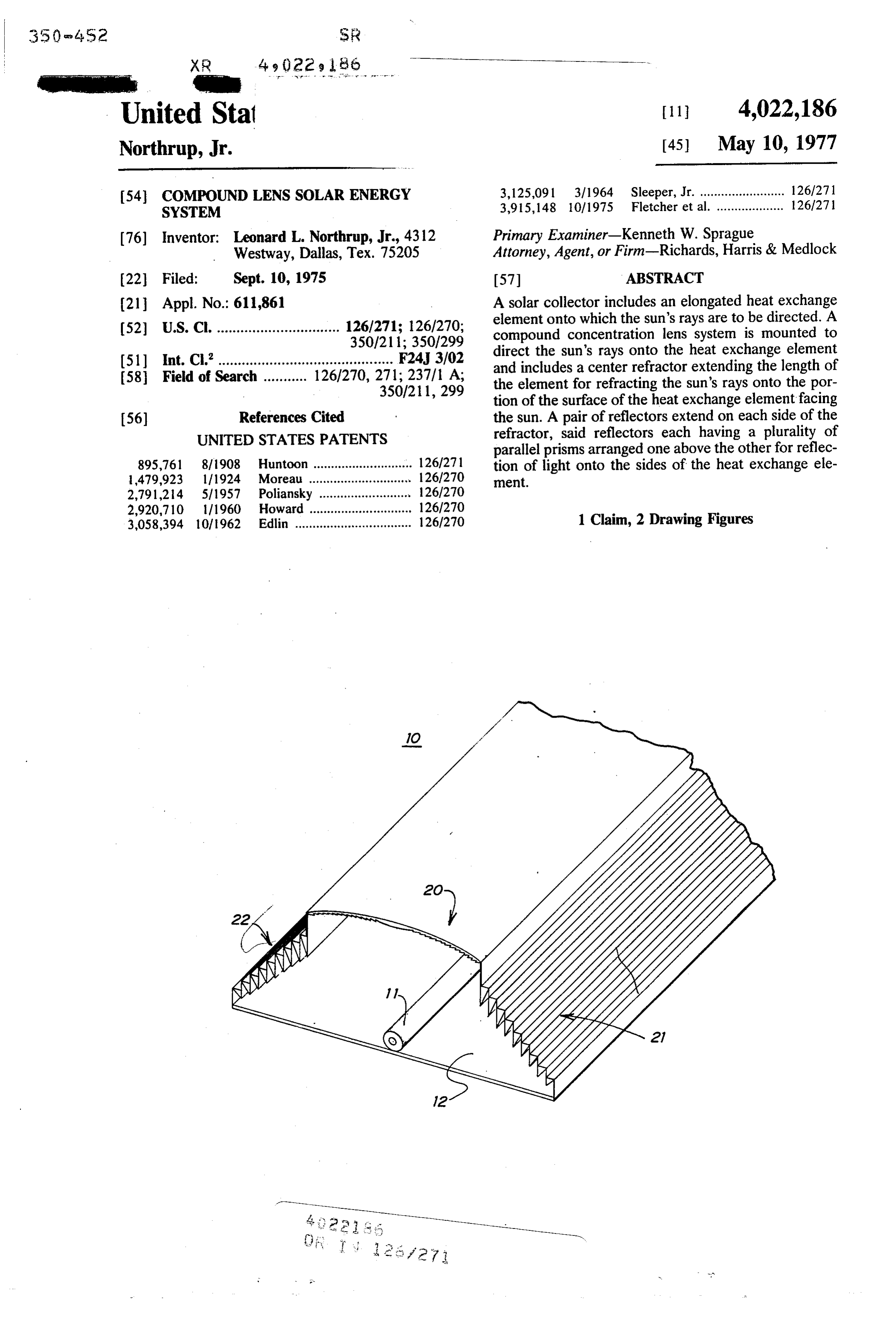
United Stat 11 4,022, 186 Northrup, Jr. (45) May 10, 1977 54 COMPOUND LENS SOLAR ENERGY 3,125,091 3/1964 Sleeper, Jr. ........................ 126/271 SYSTEM 3,915, 148 10/1975 Fletcher et al. ................... 126/271 76) Inventor: Leonard L. Northrup, Jr., 4312 Primary Examiner-Kenneth W. Sprague Westway, Dallas, Tex. 75205 Attorney, Agent, or Firm-Richards, Harris & Medlock 22 Filed: Sept. 10, 1975 57 ABSTRACT 21 Appl. No.: 611,861 A solar collector includes an elongated heat exchange (52) U.S. Cl. ............................... 126/271; 126/270; element onto which the sun's rays are to be directed. A 350/211; 350/299 compound concentration lens system is mounted to (51) int. C.’............................................ F24, 3/02 direct the sun's rays onto the heat exchange element 58 Field of Search ........... 126/270, 271; 237/1 A; and includes a center refractor extending the length of 350/211,299 the element for refracting the sun's rays onto the por tion of the surface of the heat exchange element facing 56) References Cited the sun. A pair of reflectors extend on each side of the UNITED STATES PATENTS refractor, said reflectors each having a plurality of parallel prisms arranged one above the other for reflec 895,761 8/1908 Huntoon ............................ 126/271 tion of light onto the sides of the heat exchange ele 479,923 l/1924. Moreau ............................. 126/270 ment.
2,791,214 5/1957 Poliansky ... 126/270 2,920,710 1/1960. Howard ... ... 126/270 3,058,394 101962 Edlin ................................. 126/270 1 Claim, 2 Drawing Figures
Page 2
Drawing sheet — no readable text.
Page 3
accordance with the above-identified application Ser.
COMPOUND LENS SOLAR ENERGY SYSTEM No. 532,220, now abandoned. The Fresnel lens serving as a refractor 20 operates efficiently to direct the sun's
This invention relates to solar collectors, and more rays impinging section 20 onto the surface of the heat particularly to a compound elongated collector having 5 exchange unit 11 which faces the sun. In cooperaion a refraction section and a pair of reflecting sections, therewith, the reflecting sections 21 and 22 serve to one on either side of the refracting section. reflect the sun's rays onto the sides of the heat ex The collection of solar energy for use in heating as change unit 11.
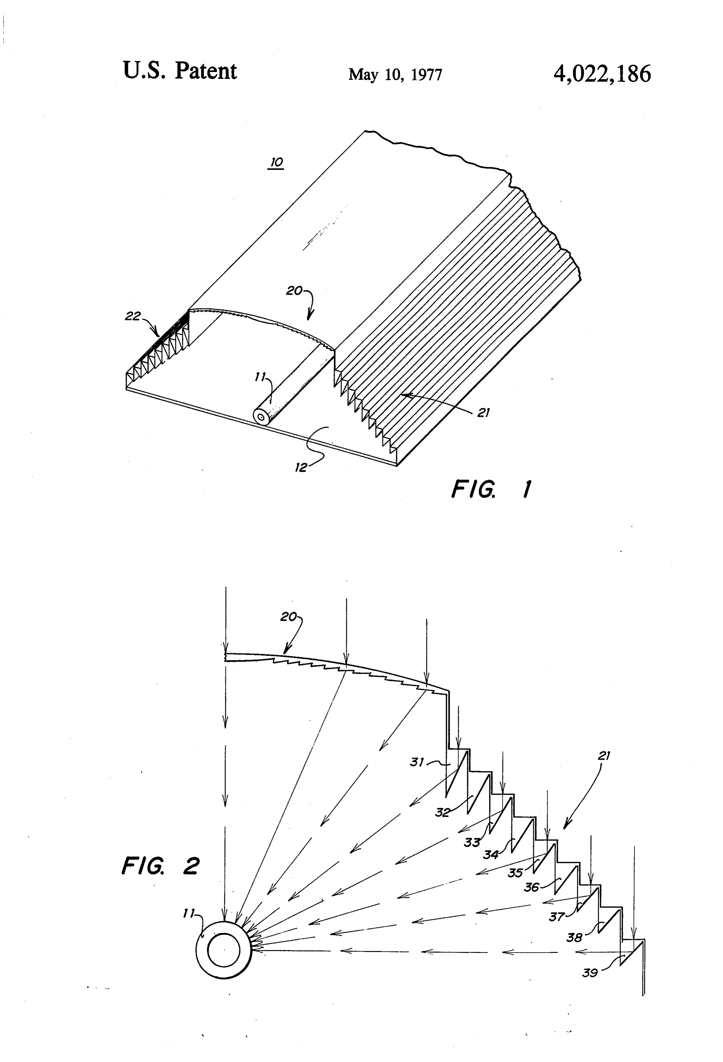
sumes greater importance as energy problems of the More particularly, as shown in FIG. 2, the side sec civilized world become more acute. There have been 10 tion 21 comprises a series of reflecting prisms 31-40. many different approaches made to the problem of Preferably, the prisms are formed as an integral elon converting solar energy into a form that may be manip gated extrusion, integral with the section 20. The prism ulated and controlled on a basis other than direct utili 40 is a right angle prism so that there is total reflection zation of the sun's rays. of incident light onto the side of the heat exchange unit Efficiency of operation and low fabrication costs are 15 11. The prisms 31-39 are arranged in a stepped rela goals which conflict. The present invention is aimed at tion above the unit 40 so that light is reflected from the optimizing both such factors. inner faces thereof onto element 11. Thus, the angles of In U.S. application Ser. No. 523,220, filed Nov. 13, the prisms 31-40 in the embodiment shown in FIG. 2 1975, for "Solar Energy Collector", now abandoned, a differ in an ordered progression.
linear Fresnel lens is disclosed serving to refract sun's 20 From FIG. 2, it will be seen that the system provides rays onto a heat exchange tube. As is known, there is a for collection of energy from the sun in a single collec critical angle dependent upon the properties of the tor from an area more than twice the area accommo media used for the lens, beyond which refraction does dated utilizing the refraction section 20 only. Thus, for not take place. Thus, a plurality of heat exchange units a given lens-collector length, i.e., focal length, the com must be employed in order to convert sun's rays im pinging a given area to the energy in a manipulatable 25 pound lens can be at least twice as wide as otherwise possible. Where the refraction section 20 becomes and useful form. inefficient, the reflection sections 21 and 22 become The present invention is directed to a system in which efficient and thus complement the refractor section 20. a compound lens is employed utilizing both reflection As illustrated in FIG. 2, the refracting and reflecting and refraction for concentrating sun's rays onto a given 30 sections heat exchange element thus reducing substantially the ing lensesareareformed as a single extrusion. The refract preferably undercut for assuring utiliza number of such elements necessary to receive sun's tion of the sun's energy impinging the entire area of the rays from a given area. refracting section 20. The reflecting prisms in section In accordance with the invention, an elongated heat 21 are shaped so that sun's rays impinging perpendicu exchange element is provided onto which the sun's rays 35 lar the outer faces of the lenses will be directed onto are to be directed. A compound lens system is mounted the sides of the heat exchange unit 11. Thus, in accor to direct sun's rays onto the element and is formed of a dance with the present invention, a solar collector com center refractor section extending the length of the prises an elongated heat exchange element 11 onto element to refract the sun's rays onto the surface of the which the sun's rays are to be directed. A compound element facing the sun with a pair of reflectors extend 40 concentration ing the length of the element, one on each side of the sun's rays ontolens system is mounted to direct the refractor with the reflectors having a plurality of paral formed of a center refractor11.20The element compound lens is extending the length of lel prisms arranged one above the other for refraction the element 11 with a pair of reflector sections extend of light onto the sides of the element. ing the length of the element, one on each side of the The novel features believed characteristic of the invention are set forth in the appended claims. The 45 refractor parallel with the reflectors each having a plurality of prisms arranged one above the other for reflec invention itself, however, as well as further objects and tion of light onto the sides of element 11. advantages thereof, will best be understood by refer Having described the invention in connection with ence to the following detailed description of an illustra certain specific embodiments thereof, it is to be under tive embodiment taken in conjunction with the accom 50 stood that further modifications may now suggest panying drawings, in which:
FIG. 1 is an isometric view illustrating the principle themselves to those skilled in the art and it is intended of the present invention; and to cover such modifications as fall within the scope of FIG. 2 is a sectional view of an embodiment of the the appended claims.
invention. What is claimed is:
Referring now to FIG. 1, a compound lens 10 has 55 1. A solar collector comprising: been illustrated which serves the purpose of concen an elongated heat exchange element onto which the trating or directing light rays from the sun onto a heat sun's rays are to be directed, exchange element 11. The heat exchange element 11 is a compound concentration lens system mounted to mounted on a base plate 12 which also supports the 60 direct sun's rays onto said element and formed of a lens. Plate 12 extends the length of element 11 and has center refractor extending the length of said ele end panels (not shown). A heat exchange fluid is to be ment to refract sun's rays onto the surface of said directed through a heat exchange element 11 so that element facing the sun, and energy from the sun's rays converted to heat in the a pair of reflectors extending the length of said ele element 11 will be carried away to a utilization system. ment, one on each side of said refractor, said re The lens 10 comprises a refracting section 20 and a 65 flectors each having a plurality of parallel prisms pair of reflecting sections 21 and 22. The refracting arranged one above the other for reflection of light section preferably will be of the Fresnel type having a onto the sides of said element.
plurality of internal refracting prisms constructed in
Provenance
- Collection
- Cited prior art
- Original PDF
- patentimages.storage.googleapis.com →
- Filed
- 1975-09-10
- Pages
- 3
- Method
- pdftotext (the PDF's own text layer) + pdftoppm 300dpi page scans
- Source
- Google Patents bibliographic record
- Granted
- 1977-05-10
- Inventors
- Leonard L. Northrup, Jr.
- Transcribed from
- patentimages.storage.googleapis.com →