patent · US3088882
Solar still
7 May 1963
Page 1
Drawing sheet — no readable text.
Page 2
United States Patent Office Patented May 7, 1963
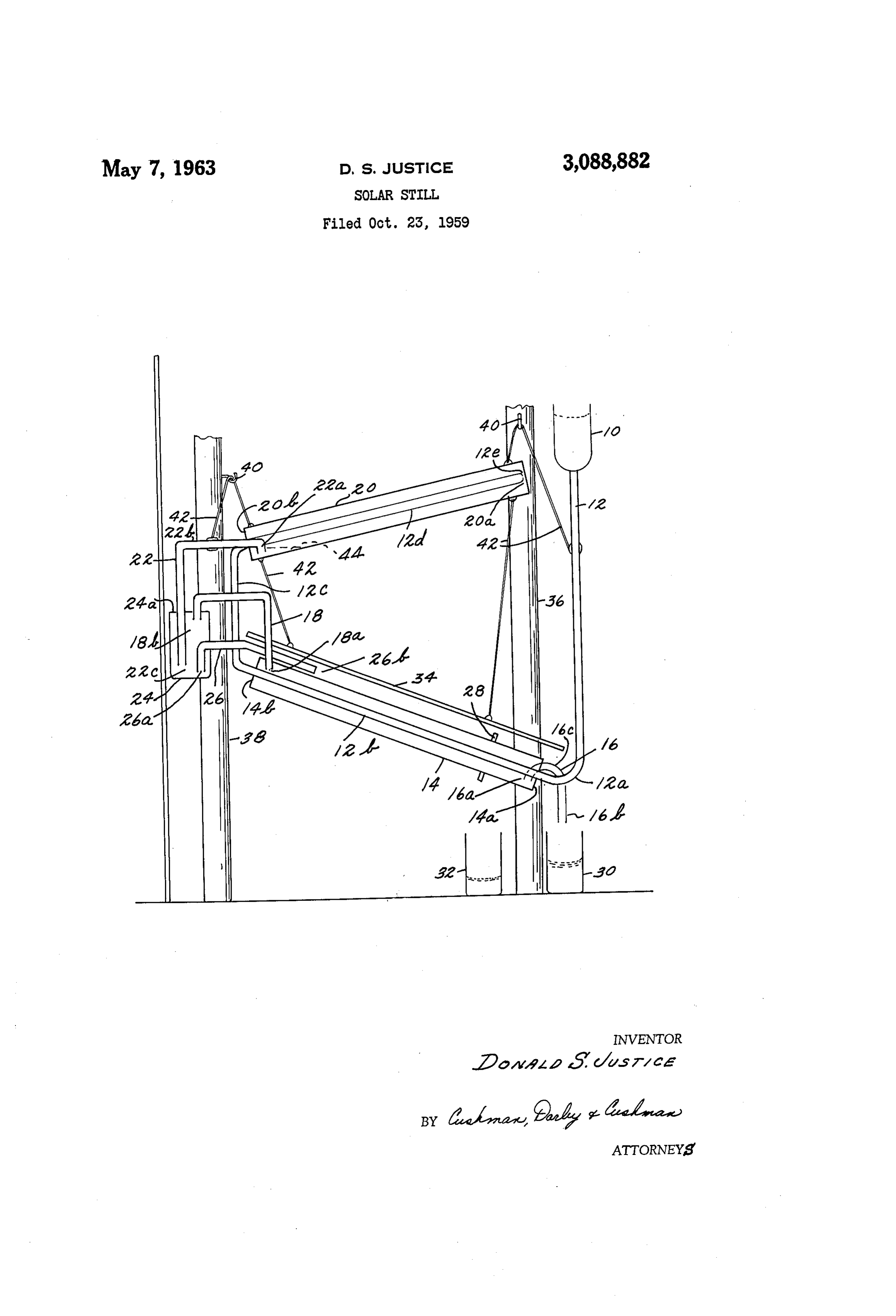
extends downwardly to an open outlet end 22c located 3,088,882 within a housing 24 into which the siphon device empties. SOLAR STELL The latter is provided with a top cover 24a which closes Donald S. Justice, Arington, Va., assignor to The Justice container 24 except for the entry of conduits 22 and 8, Company, Washington, D.C., a corporation of the Fis the previously mentioned inlet end 18b of conduit 18 trict of Colabia being located just beneath the cover 24a. Within the Fied Oct. 23, 1959, Ser. No. 848,445 housing 24 is also the open inlet end 26a of a conduit 26 2 Cairns. (C. 202-2695) which emerges from the housing 24 above the lower open This invention relates to apparatus for vaporizing and exit end 22c of conduit 22. The open outlet end 26b of re-condensing liquids so as to purify same or for other 10 conduit 26 is positioned above the housing 4. purposes. In accordance with the invention, heat lib Surrounding Near the lower end of housing 14 is a shoulder 28 erated by condensing liquid is utilized to preheat liquid the housing.
which is to be vaporized, thereby increasing the volatility Reference character 30 designates any suitable container of the latter. The heat exchange in the preheating step which may be placed beneath the open outlet end 16b of is a cooling influence which aids condensation of vapor. 5 conduit 16 for collecting liquid which has been vaporized and re-condensed. Reference character 32 designates any
Additionally, in accordance with the invention, radiant suitable vessel placed beneath shoulder 28 for collecting heat such as to be derived from ordinary sunshine is liquid which has not been vaporized. used to enhance the vaporization of liquid.
The principal object of the invention is to provide im 20 forReference character 34 designates a member suitable suspension above the housing 14 and components proved apparatus for the vaporization and re-condensation therein for shading same from the direct rays of the sun. of liquids. The entire apparatus may be supported by any suitable An additional object is to utilize radiant heat such as means such as typical fence posts 36 and 38, by use of ordinary sunshine to enhance the operation of the ap hooks 40 and suitable suspension wires or cords 42.
A still further object of the invention is to provide a 25 The operation of the illustrative embodiment is as fol very compact and simple structure which may be as lows: First assume the entire apparatus to be empty of sembled of inexpensive parts and readily erected at any liquid. Next assume that a quantity of liquid to be vapor place. ized and redistilled-such as salt water to be purified-is Further objects and the entire scope of the invention 30 flowpoured into the top of reservoir 10. This liquid will will become apparent from the following detailed de downwardly through conduit 12, thence upwardly scription of an illustrative embodiment. through its inclined section 12b, further upwardly through The illustrative embodiment of the invention can be best the vertical section 12c, and further upwardly through the understood by reference to the accompanying drawing. section 12d to the open end 12e within housing 20. From Reference character 10 designates a cylindrical reser 35 ing open end 12e the liquid will flow downwardly in hous voir for liquid to be vaporized and re-condensed, this 20, and some will vaporize. Whatever portion which cylinder being open at the top and communicating at the does not vaporize will collect in housing 20 until the level bottom with a conduit 12 having several parts or sections rises to the extent designated by reference character 44 as follows: The first section designated 12 extends down whereupon the liquid will run through the conduit sec wardly to an elbow section 12a followed by a section 12b, 40 tion 22b and out the open end thereof 22c into the hous rising at an angle above the lowermost point of the ingAt24.this point it is to be understood that the cross elbow 12a. The next following section is 12c extending Sectional area of conduit 22 is to be greater than the cross upwardly, and then a final section 12d inclined upwardly Sectional area of opening 12e. Liquid in conduit 22 will and shown directed back toward the reservoir 10. The end of the conduit 12 designated 12e has a certain cross 45 cause it to act as a self-priming syphon. Inasmuch as sectional area of opening, explained in greater detail the cross-sectional area of conduit 22 is greater than that of opening 12e, the supply of liquid in housing 20 will hereinafter.
Section 12b of conduit 2 is surrounded by a housing be rapidly depleted until the level 44 has gone below the open end 22a of conduit 22. At this moment a slug of member 14, shown as cylindrical and closed at its ends vapor from within housing 20 will be attracted into the 14a and 14b, these ends, however, permitting the conduit 50 conduit section 12b to extend therethrough. At end 14a of hous 22. However, liquid from opening 12e will again ing 14 is also located a conduit 16, passing through end begin to fill the housing 20 above its open end 22a. In 14a, this conduit having an open intake end 16a and an through this way, alternate slugs of liquid and vapor will pass open outlet end 16b, the latter end may be at a lower conduit 22 into housing 24, and this action will level than the intake end 16a, and there being a central 55 in be such as to substantially reduce the vapor pressure with point 16c of conduit 16 at an elevation above intake the housing 20. The reduction in pressure will enhance end 16a. the vaporization of liquid within housing 20. At its upper end housing 14 is further characterized by In housing 24, after a certain amount of liquid falls entry thereinto of a conduit 18 having an open outlet thereinto from conduit 22, housing 24 will become filled end 18.a. An open inlet end 18b is provided in conduit 6 with liquid to the level of the horizontal section of con 8, as will be explained in greater detail hereinbelow. duit 26, whereupon this liquid will pass therethrough and Section 2d of conduit 12 is surrounded by a housing out the open end 26b, whence it drops upon the housing 20, which may be cylindrical or of any convenient cross 4. In the meanwhile, vapor liberated through the end sectional shape. Housing 20 is closed at its upper ex 22c of conduit 22 will rise and collect in the upper end tremity by end 20a, and at its lower extremity by end 65 of the housing 24, and pass through conduit 18 into 20b, the latter permitting, however, the entry of conduit housing 14.
12 between its sections 12c and 12d. Also entering end Liquid dropping from opening 26b of conduit 26 onto 20b of housing 20 is a conduit 22 having an open intake the outside of housing 14 will tend to cling to the hous end 22a located near the bottom of housing 20 adjacent ing 14 and run down along the exterior thereof, vaporiz the end thereof 20b. Conduit 22 is further characterized 70 ing as it does so. Whatever liquid reaches the shoulder by a section 22b extending at an elevation slightly above 28 without having vaporized will fall into the container the open end 22a. The remaining portion of conduit 22 32, and this liquid may be returned to the reservoir 10.
Page 3
Within the housing 14, vapor issuing from opening liquid to be purified, a first conduit section, a second i8a of conduit 18 will condense. Condensation will oc conduit section positioned above the first conduit section, cur because of several factors, one being that the latent a conduit section joining said supply container to the heat of condensation may be exchanged into the relatively inlet end of the first conduit section, a conduit section cold liquid passing through conduit section 12b. By suit joining the outlet end of the first conduit section with able shading also of reservoir 10, the coolness of the liquid the inlet end of the second conduit section, an upwardly and therefore the condensation may be enhanced. As extending evaporation enclosure means about said second above stated, liquid on the exterior of housing 14 from conduit, an outlet opening of predetermined cross sec conduit 26 will be vaporized, and this also serves to ex tional area in said second conduit section within said tract heat from the housing 14, thus enhancing the con O enclosure means, a siphon device having an intake within densation of vapor therein. If desired, suitable fins (not said evaporation enclosure below the level of said outlet shown) or other conventional means may be employed opening in said conduit therein, the siphon intake having on the exterior of conduit section 2b and on the interior a greater cross Sectional area than said outlet opening, of housing 4 so as to further enhance the opportunity Whereby the siphon device extracts alternate quantities of for vapors from 18a to be cooled and therefore to con 5 liquid and vapor from said evaporation enclosure, a hous dense. ing into which said siphon empties, a vapor outlet conduit Liquid condensing within housing 14 collects at the from said housing, a downwardly extending condensa bottom end and enters the conduit 16 via its intake end tion enclosure about said first conduit, the vapor outlet 16a. As soon as this liquid has risen to the level of the conduit from said housing communicating with said con water level 16c of conduit 16, it will syphon over and 20 densation enclosure, and a discharge opening from the run into vessel 30. condensation enclosure at a point below the entry there It will be understood that with the housing 20 exposed into of said vapor outlet conduit, the arrangement being to direct rays of the sun, the heating effect within this Such that said siphon means will withdraw liquid from housing will enhance the vaporization action. said evaporation enclosure more rapidly than liquid enters Action of the apparatus is further enhanced by causing Same, thereby reducing the vapor pressure within said
a black exterior surface to be present on housing 20, for evaporation enclosure and enhancing evaporation, and the absorbing heat. Additionally a white or reflective ex vapor expelled from said siphon means is cooled by in terior surface on housing 14 will reduce absorption of coming liquid in said first conduit within said condensa heat by radiation, and enhance the condensing action 30 tion enclosure to enhance the condensation of said vapor within this housing. to produce purified liquid within the latter enclosure. It will be noted that in the event of complete vaporiza 2. Apparatus as in claim 1 and further including a tion within the evaporator housing 20, the vapor will have conduit connected with the housing into which said siphon open passageway and flow by gravity into the condenser means empties for extracting liquid from said siphon section within the housing 14. means and running same over the outer surface of said It will now be further apparent that the invention condensation enclosure to further cool same and enhance basically provides a compact vaporization and re-con said condensation therein.
densation apparatus wherein liquid flowing to a zone of vaporization absorbs heat from a zone of condensation. References (Cited in the file of this patent Additionally, the rays of the sun may be utilized to heat UNITED STATES PATENTS and therefore enhance the vaporization action, while the condensation section may be shaded from the direct rays 1,466,221 Foster et al. ------------ Aug. 28, 1923 of the Sun, to enhance the re-condensation action. 2,025,724 Clendenin ------------- Dec. 31, 1935 The purpose of the foregoing description of an illustra 2,141,330 Abbot ---------------- Dec. 27, 1938 tive embodiment is simply to aid in an understanding of 45 2,342,062. Schenk ---------------- Feb. 15, 1944 the invention, and the true scope thereof is to be deter 2,379,519 Hall ------------------- July 3, 1945. mined by the following claims. 2,424,142. Bimpson et al. ---------- July 15, 1947, I claim: 2,490,659. Snyder ----------------- Dec. 6, 1949. 1. Purification apparatus comprising container means 2,515,013 Kruhmin -------------- July 11, 1950 at a predetermined elevation for containing a supply of 50 2,716,446 Ross ------------------ Aug. 30, 1955
Provenance
- Collection
- Cited prior art
- Original PDF
- patentimages.storage.googleapis.com →
- Filed
- 1959-10-23
- Pages
- 3
- Method
- pdftotext (the PDF's own text layer) + pdftoppm 300dpi page scans
- Source
- Google Patents bibliographic record
- Granted
- 1963-05-07
- Inventors
- Donald S Justice; Justice Co
- Transcribed from
- patentimages.storage.googleapis.com →