patent · US4002031
Solar energy converter with waste heat engine
11 January 1977
Page 1 — bibliographic record
United States Patent to ll 4,002,031 Bell 45 Jan. 11, 1977
54 SOLAR ENERGY CONVERTER WITH
WASTE HEAT ENGINE OTHER PUBLICATIONS W. A. Beckman, et al., “Design Considerations for a (75) Inventor: Ronald L. Bell, Woodside, Calif. 50-Watt Photovoltaic Power System Using Concen trated Solar Energy,' Solar Energy, vol. 10, No. 3, pp.
73 Assignee: Varian Associates, Inc., Palo Alto, 132-136 (1966).
Calif. H. J. Hovel, et al., “Ga-Al-As-GaAs P-P-N Hetero junction Solar Cells,” J. Electrochem. Soc. vol. 120, No.
22) Filed: July 7, 1975 9, pp. 1246-1252 (1973).
R. Davis, et al., “Operation of GaAs Solar Cells at High 21 Appl. No.: 593.913 Solar Flux Density,' Solar Energy, vol. 17, p. 145
52 U.S. Cl. ................................. 60/641; 126/270; Primary Examiner-F.C. Edmundson 126/271; 136/89 PC Assistant Examiner-Aaron Weisstuch (51) Int. Cl.’..................... F03G 7/02; HOL 31/06 Attorney, Agent, or Firm-Stanley Z. Cole; Richard B. 58) Field of Search ............. 136/89; 126/270, 271; Nelson; Robert K. Stoddard
(56) References Cited A solar energy converter uses gallium arsenide photo voltaic cells to convert light to direct current. Optical
UNITED STATES PATENTS concentrators reduce the needed area of cells. Gallium 2,946,945 7|1960 Regnier et al. .................. 136189 X arsenide retains high conversion efficiency up to sev 2,989,575 6, 1961 Wallace, Jr. ......................... 136189 eral hundred degrees, so the waste heat may be used to 3,675,026 6/1969 Woodal ....... ... 250/21 1 J produce mechanical power in a Rakine cycle engine. 3,822,692 7 11974 Demarest .......................... 26/271 3,841,738 Of 1974 Caplan .............................. 35O1293 5 Claims, 3 Drawing Figures
Page 2
Drawing sheet — no readable text.
Page 3
Drawing sheet — no readable text.
Page 4
an array of cells are electrically connected in series by
SOLAR ENERGY CONVERTER WITH WASTE connecting wires 17 to negative and positive output HEAT ENGINE terminals 18, 19. In this way the electromotive forces of the cells, of the order of one volt, are added to form a
FIELD OF THE INVENTION 5 commercially useful dc voltage.
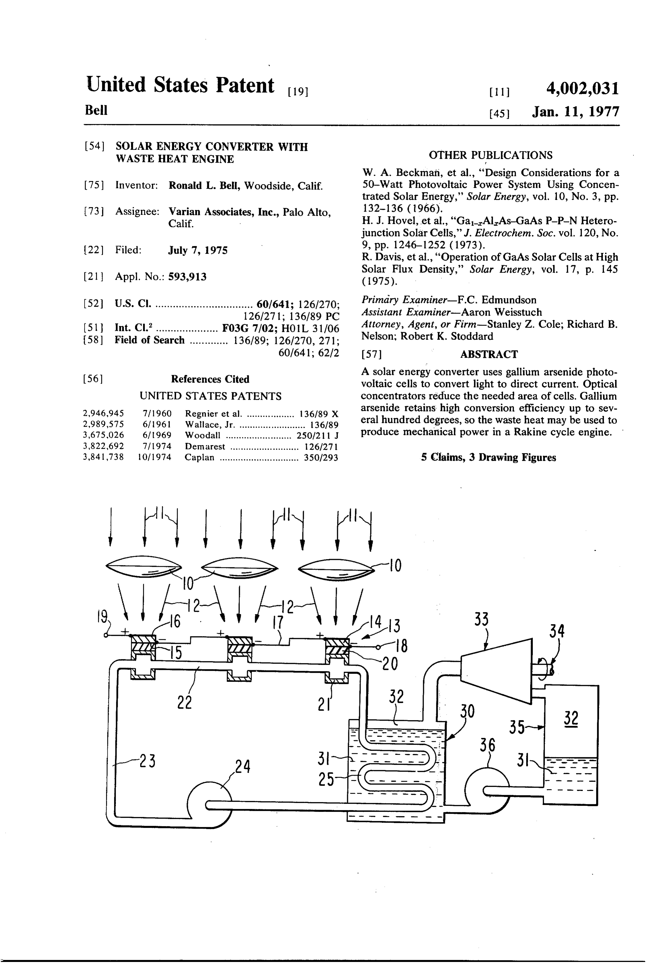
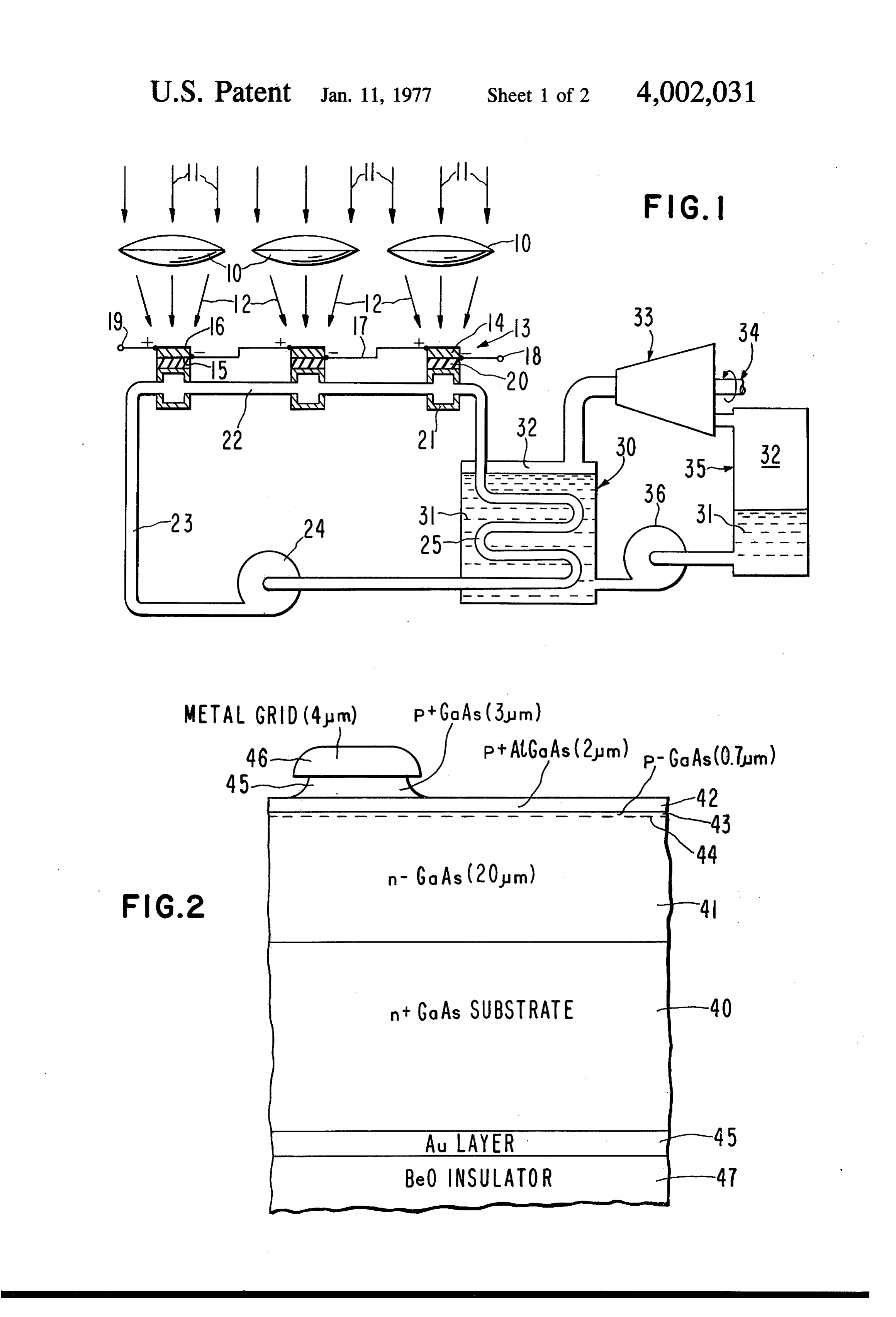
This invention relates to the conversion of solar radi Each cell 13 is thermally bonded to a thermally con ant energy to electrical and mechanical power. ducting insulator 20, as of beryllia ceramic. Insulators Schemes for the direct utilization of solar energy 20 are in turn bonded to metallic heat exchangers 21. A have had limited utility but widespread inventive effort. cooling fluid 23 circulating through pipes 22 flows With the impending inadequacy of fossil fuels, direct O through heat exchangers 21, removing the portion of solar conversion can become economically feasible. absorbed solar energy which is not converted to elec tricity, typically 80 to 85%. If cooling fluid 23 is a good
PRIOR ART insulator, such as gaseous helium or a silicone liquid, It has long ago been proposed to convert solar energy insulators 20 will not be needed, but corresponding to heat, and use the heat to drive a conventional heat 15 insulation in the connecting pipes would be required. engine such as a steam turbine. The mechanical energy Cooling fluid 23 may be water or a liquid metal. It also would then be converted to electrical energy. The effi may be a vaporizable working fluid for the heat engine, ciency of this process is necessarily low because the the vaporization taking place directly in heat exchang thermodynamic efficiency is limited by the available ers 21. For maximum thermal efficiency exchangers 21 temperature difference. 20 may be piped in parallel instead of the series piping 22 More recently it has become possible to convert shown.
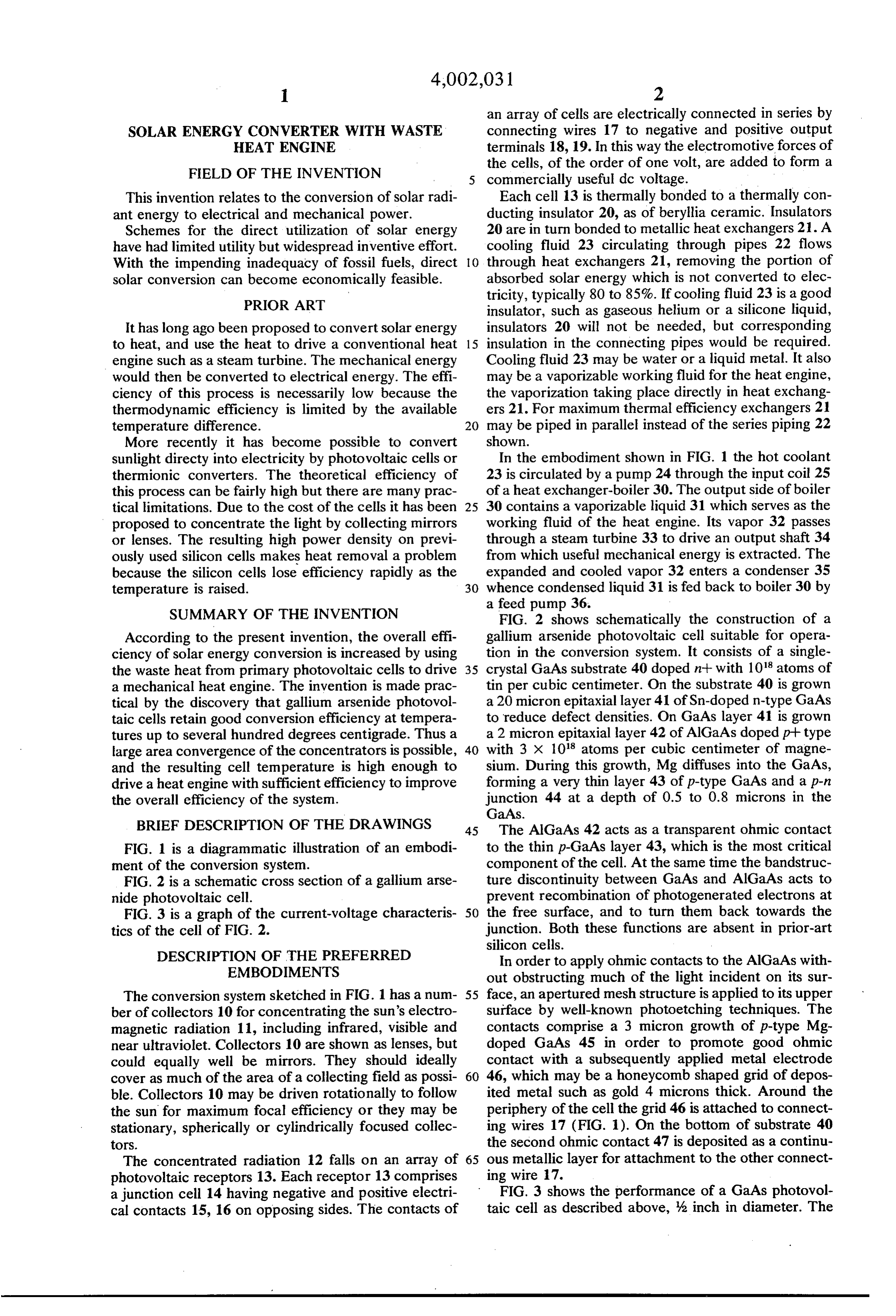
sunlight directy into electricity by photovoltaic cells or In the embodiment shown in FIG. 1 the hot coolant thermionic converters. The theoretical efficiency of 23 is circulated by a pump 24 through the input coil 25 this process can be fairly high but there are many prac of a heat exchanger-boiler 30. The output side of boiler tical limitations. Due to the cost of the cells it has been 25 30 contains a vaporizable liquid 31 which serves as the proposed to concentrate the light by collecting mirrors working fluid of the heat engine. Its vapor 32 passes or lenses. The resulting high power density on previ through a steam turbine 33 to drive an output shaft 34 ously used silicon cells makes heat removal a problem from which useful mechanical energy is extracted. The because the silicon cells lose efficiency rapidly as the expanded and cooled vapor 32 enters a condenser 35 temperature is raised. 30 whence condensed liquid 31 is fed back to boiler 30 by a feed pump 36.
SUMMARY OF THE INVENTION FIG. 2 shows schematically the construction of a According to the present invention, the overall effi gallium arsenide photovoltaic cell suitable for opera ciency of solar energy conversion is increased by using tion in the conversion system. It consists of a single the waste heat from primary photovoltaic cells to drive 35 crystal GaAs substrate 40 doped n-- with 10 atoms of a mechanical heat engine. The invention is made prac tin per cubic centimeter. On the substrate 40 is grown tical by the discovery that gallium arsenide photovol a 20 micron epitaxial layer 41 of Sn-doped n-type GaAs taic cells retain good conversion efficiency at tempera to reduce defect densities. On GaAs layer 41 is grown tures up to several hundred degrees centigrade. Thus a a 2 micron epitaxial layer 42 of AlGaAs doped p-type large area convergence of the concentrators is possible, 40 with 3 x 10' atoms per cubic centimeter of magne and the resulting cell temperature is high enough to sium. During this growth, Mg diffuses into the GaAs, drive a heat engine with sufficient efficiency to improve forming a very thin layer 43 of p-type GaAs and a p-n the overall efficiency of the system. junction 44 at a depth of 0.5 to 0.8 microns in the GaAs.
BRIEF DESCRIPTION OF THE DRAWINGS 45 The AlGaAs 42 acts as a transparent ohmic contact FIG. 1 is a diagrammatic illustration of an embodi to the thin p-GaAs layer 43, which is the most critical ment of the conversion system. component of the cell. At the same time the bandstruc FIG. 2 is a schematic cross section of a gallium arse ture discontinuity between GaAs and AlGaAs acts to nide photovoltaic cell. prevent recombination of photogenerated electrons at FIG. 3 is a graph of the current-voltage characteris 50 the free surface, and to turn them back towards the tics of the cell of FIG. 2. junction. Both these functions are absent in prior-art silicon cells.
DESCRIPTION OF THE PREFERRED In order to apply ohmic contacts to the AlGaAs with EMBODIMENTS out obstructing much of the light incident on its sur The conversion system sketched in FIG. 1 has a num 55 face, an apertured mesh structure is applied to its upper ber of collectors 10 for concentrating the sun's electro surface by well-known photoetching techniques. The magnetic radiation 11, including infrared, visible and contacts comprise a 3 micron growth of p-type Mg near ultraviolet. Collectors 10 are shown as lenses, but doped GaAs 45 in order to promote good ohmic could equally well be mirrors. They should ideally contact with a subsequently applied metal electrode cover as much of the area of a collecting field as possi 60 46, which may be a honeycomb shaped grid of depos ble. Collectors 10 may be driven rotationally to follow ited metal such as gold 4 microns thick. Around the the sun for maximum focal efficiency or they may be periphery of the cell the grid 46 is attached to connect stationary, spherically or cylindrically focused collec ing wires 17 (FIG. 1). On the bottom of substrate 40 torS. the second ohmic contact 47 is deposited as a continu The concentrated radiation 12 falls on an array of 65 ous metallic layer for attachment to the other connect photovoltaic receptors 13. Each receptor 13 comprises ing wire 17.
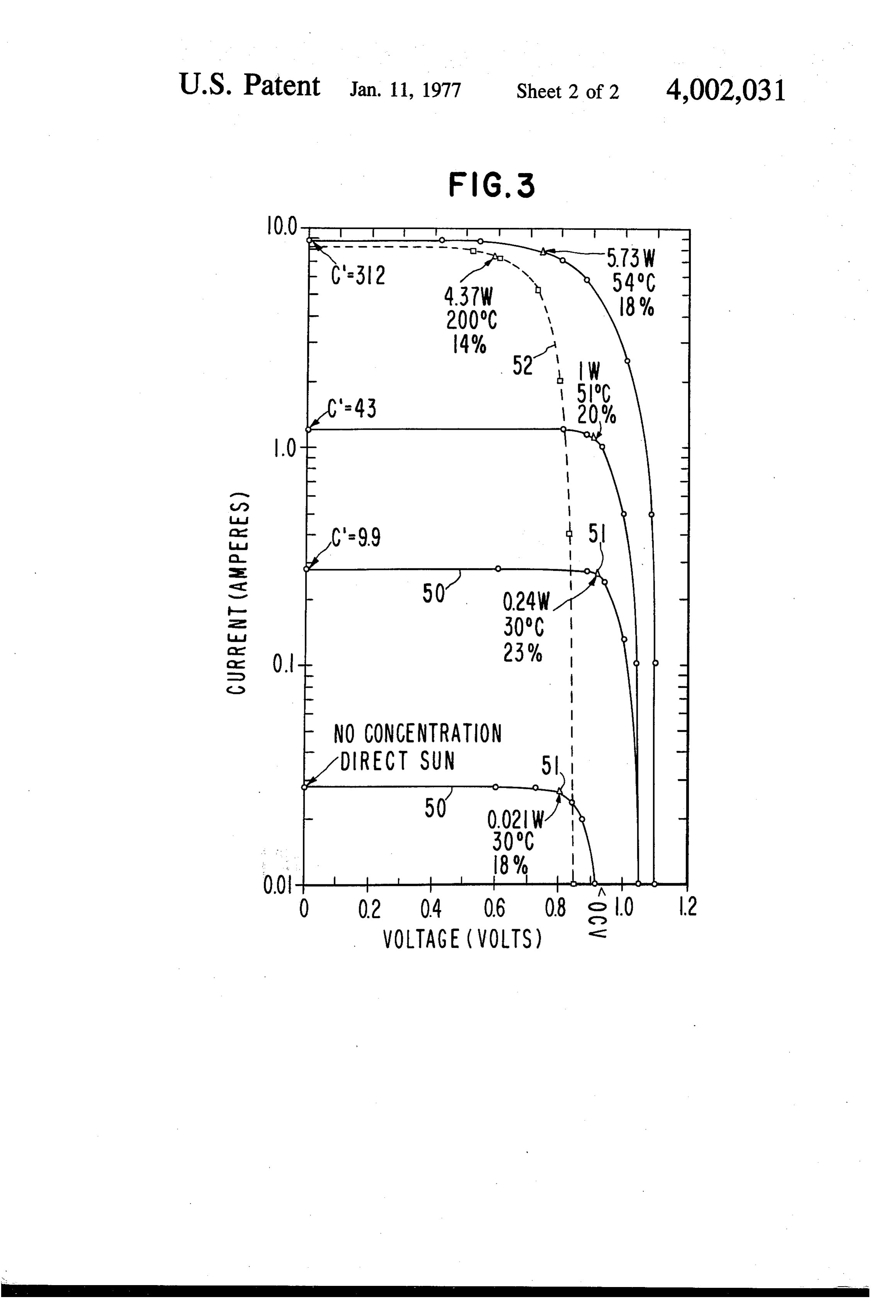
a junction cell 14 having negative and positive electri FIG. 3 shows the performance of a GaAs photovol cal contacts 15, 16 on opposing sides. The contacts of taic cell as described above, 3 inch in diameter. The
Page 5
individual curves 50 are the current-vs-voltage charac art. The preferred embodiments described above are teristics, each taken with a different degree of area thus to be interpreted as illustrative and not limiting, What is claimed is:
concentration C" of direct sunlight. For each curve 50, . A solar energy converter comprising: the point of maximum power output (i.e., maximum collector means for concentrating solar electromag efficiency) 51 is marked, and the power output, cell netic radiation, temperature and conversion efficiency (with a convec a gallium arsenide junction cell for receiving said tive heat sink) are indicated. concentrated radiation and converting a portion Curve 52 is the performance when the cell tempera thereof to electrical energy, ture was allowed to rise to 200° C. The conversion 10 means for transferring heat from said cell to a circu efficiency fell only from 18% to 14%. The loss in power lating fluid, and output would be more than made up by a reasonably heat engine means for converting a portion of said efficient heat engine operating at a 200° C maximum heat to mechanical energy.
temperature, such as a Rankine cycle engine with a 15 arsenide The apparatus of claim 1 wherein said gallium cell comprises a layer of gallium aluminum
Vaporizable working fluid. Saturated steam pressure at arsenide as a transparent contact.
200 C is 200 pounds per square inch, adequate for 3. The apparatus of claim 2 wherein said layer of turbine operation. The overall system efficiency would gallium aluminum arsenide is an epitaxial layer on the thus be improved. Also, there are indications that the side of said cell receiving said concentrated radiation. GaAs cells may operate reliably as high at 300° C, 20 4. The apparatus of claim 1 wherein said cell includes corresponding to a saturated steam pressure of 1246 an apertured, metallically conductive contact layer on pounds per square inch. the side of said cell receiving said concentrated radia tion.
The above are specific examples of a system for con 5. The apparatus of claim 4 wherein said contact verting solar energy directly to electricity and indi 25 layer overlays a layer of expitaxial gallium aluminum rectly to mechanical energy. Many variations of the arsenide.
inventive system will be obvious to those skilled in the ck ck k ck sk
Provenance
- Collection
- Cited prior art
- Original PDF
- patentimages.storage.googleapis.com →
- Filed
- 1975-07-07
- Pages
- 5
- Method
- pdftotext (the PDF's own text layer) + pdftoppm 300dpi page scans
- Source
- Google Patents bibliographic record
- Granted
- 1977-01-11
- Inventors
- Ronald L. Bell; Varian Associates Inc
- Transcribed from
- patentimages.storage.googleapis.com →