patent · US4187123
Directionally controlled array of solar power units
5 February 1980
Page 1 — bibliographic record
United States Patent (19) 11) 4,187,123 Diggs 45) Feb. 5, 1980
DIRECTIONALLY
SOLAR POWERCONTROLLED
UNTS ARRAY FOREIGN PATENT DOCUMENTS 909092 11/1945 France ..................................... 126/27 (76 Inventor: Richard E. Diggs, 12 A Rd., Primary Examiner-J. V. Truhe Carthage, Mo. 64836 Assistant Examiner-Eugene S. Indyk (21) Appl. No.: 851,718 Attorney, Agent, or Firm-Shoemaker and Mattare, Ltd.
22 Filed: Nov. 15, 1977 A directionally controlled array of solar power units includes a supporting frame having conduits for flow of
Related U.S. Application Data hot and coldwater to each of the units supported on the ... --- . . . - - - -- frame, and each unit includes a solar cell which directly 63 A.guation of Ser. No. 624,396, Oct. 21, 1975, aban- converts solar energy into electrical energy, the solar energy being concentrated on the cells by lenses. The 2 solar cells are electrically connected for desired use of
126/425; 126/440; 136/89 PC cold water conduits are connected with the cells for
to cool inheatandexchange the cells relationship.
heat the water and theWith hot water is available for work. Thermocouples and con (56) References Cited trols are connected with the units for moving the units to keep them pointed at the sun to thus utilize maximum
3,965,683 6/1976 Dix ......................................... 60/64 3,976,508 8/1976 Mlavsky ................................. 60/641 8 Claims, 9 Drawing Figures
(\ or Are Y same w
COLD WATER
Page 2
Drawing sheet — no readable text.
Page 3
Drawing sheet — no readable text.
Page 4
Drawing sheet — no readable text.
Page 5
Drawing sheet — no readable text.
Page 6
solar energy on the solar cell, and means for circulating
DIRECTIONALLY CONTROLLED ARRAY OF water in heat exchange relationship with the solar cell SOLAR POWER UNTS to heat the water.
Yet another object of the invention is to provide a
This is a continuation, of application Ser. No. 5 directionally controlled array of solar power units 624,396, filed Oct. 21, 1975 now abandoned. which is simple and economical in construction and accurate in operation and which is exceptionally energy
BACKGROUND OF THE INVENTION efficient.
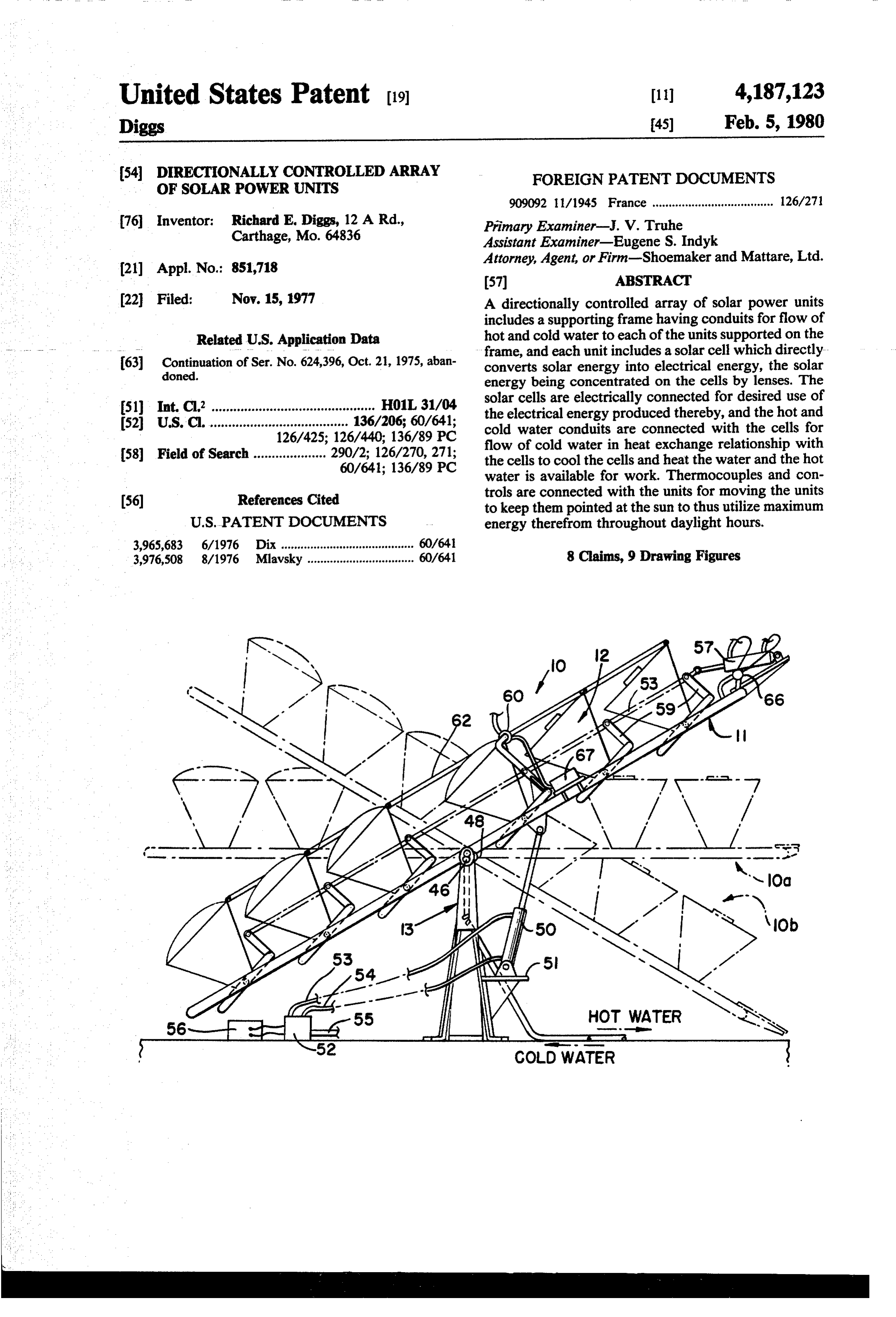
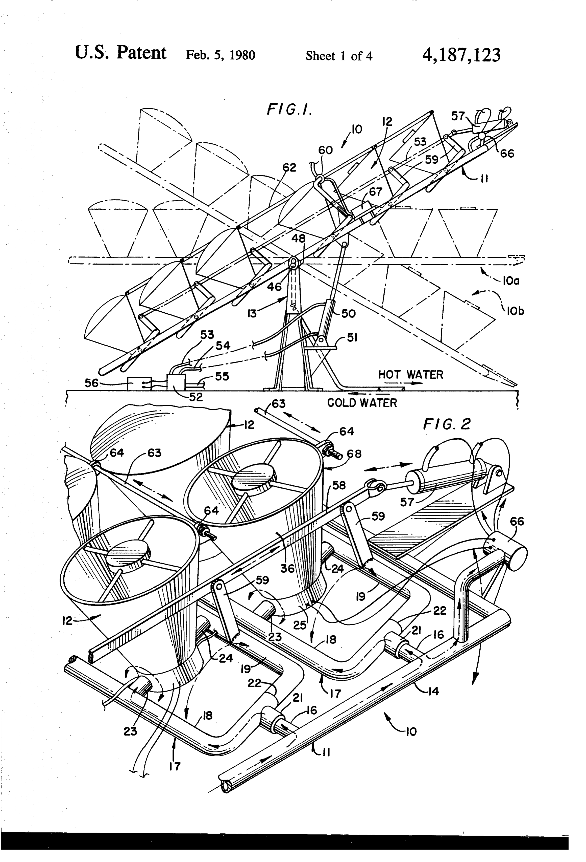
. This invention relates to a solar powered means for BRIEF DESCRIPTION OF THE DRAWINGS producing work, and more particularly, relates to such 10 a device which utilizes solar cells for direct conversion FIG. 1 is a view in elevation of a directionally con of solar energy into electrical energy and also utilizes trolled array of solar power units according to the in water circulated in heat exchange relationship with the vention, with the array shown in one of its positions in solar cells to both cool the solar cells and heat the wa full lines and in two of its other positions in phantom ter, whereby the heated water may be used for work. 15 lines.
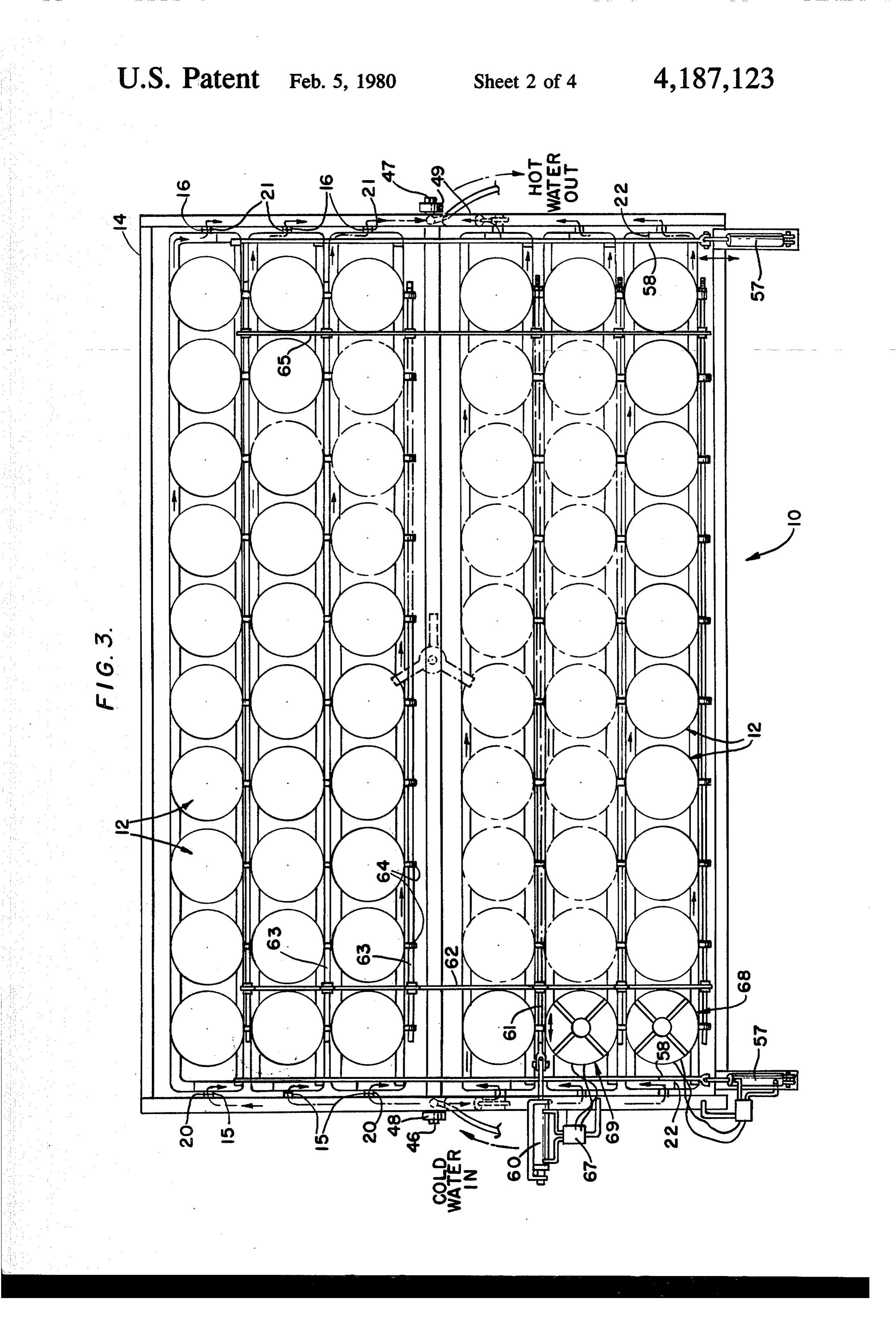
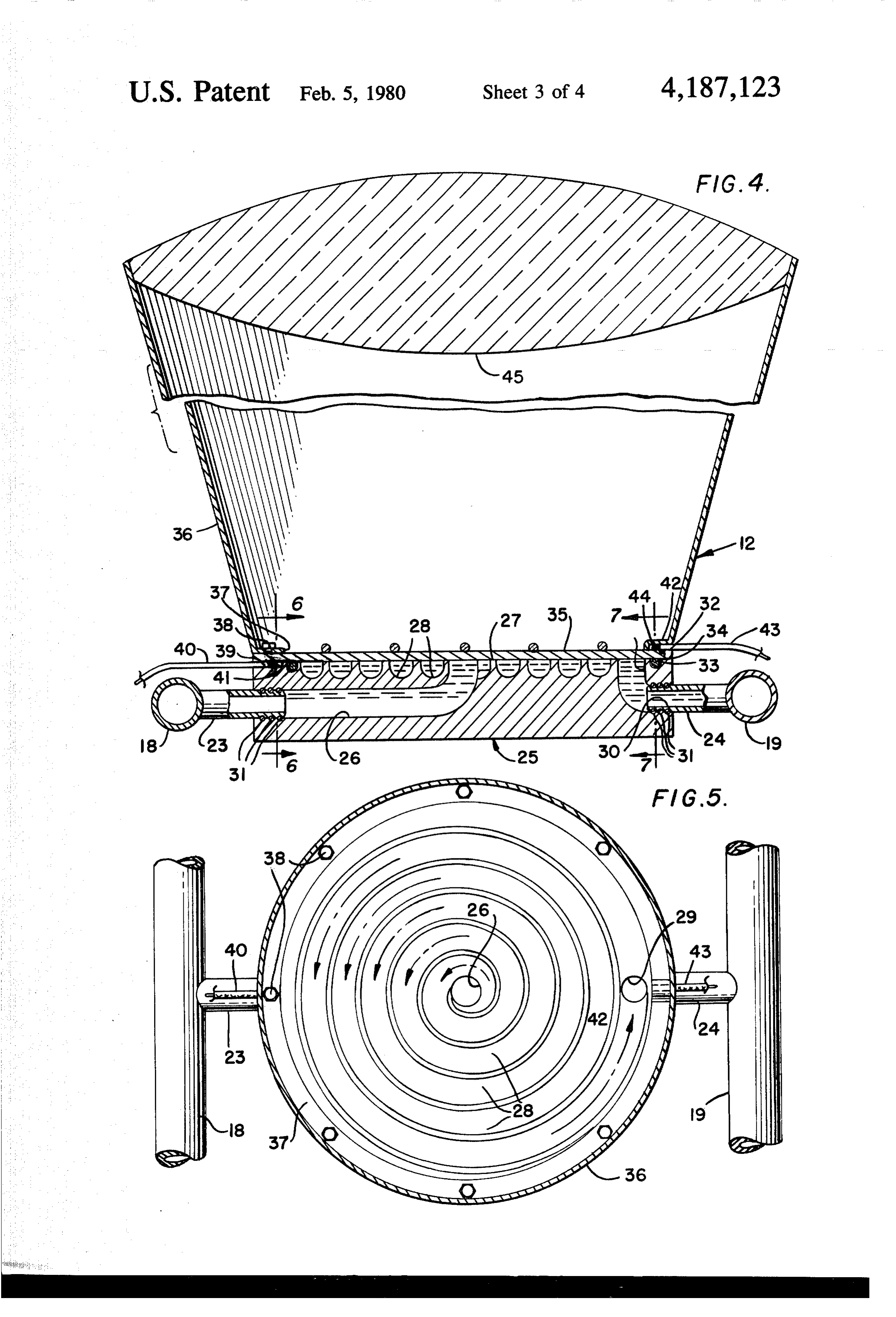
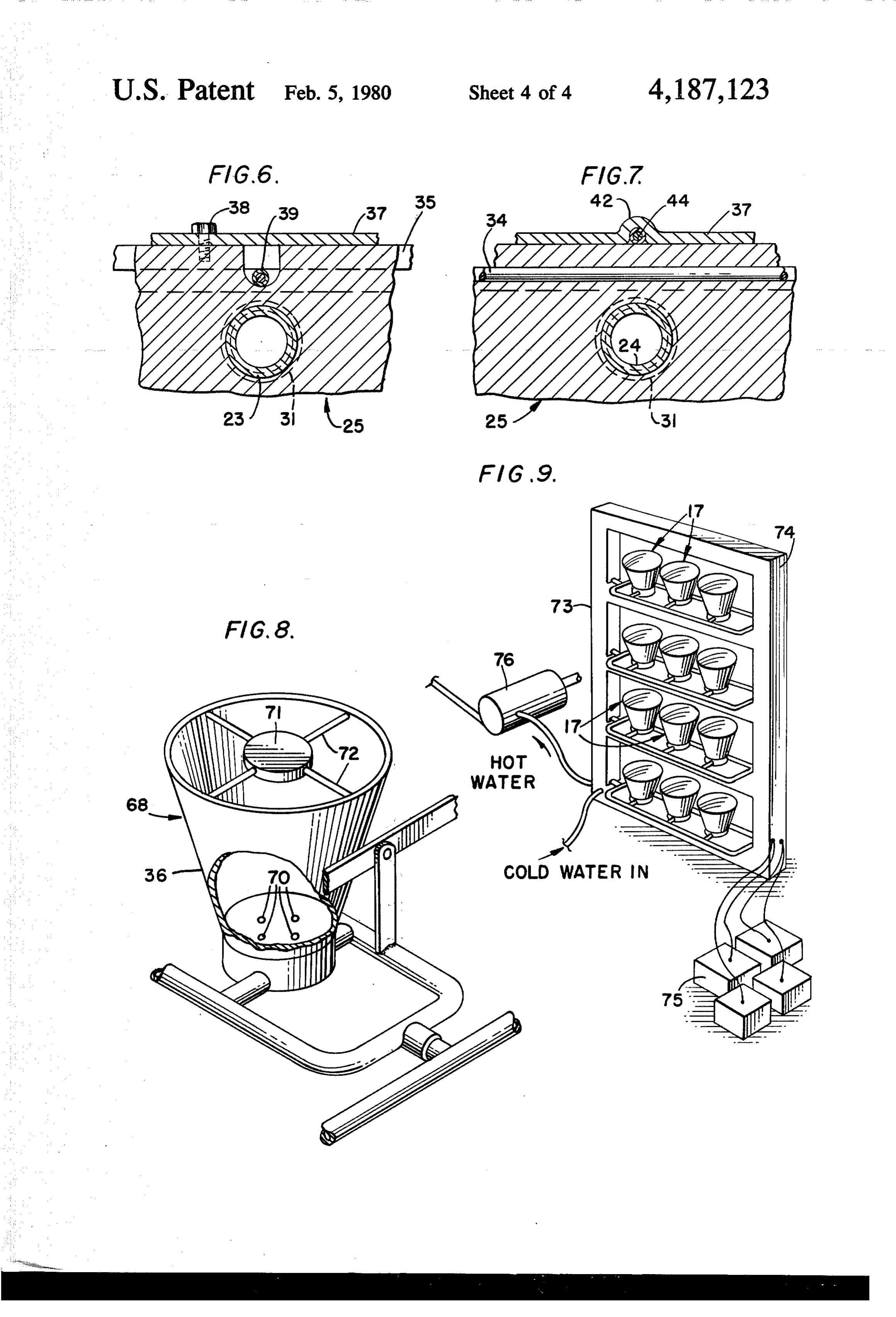
Specifically, in accordance with the invention, con FIG. 2 is a greatly enlarged, fragmentary, perspective trol means are connected with the power units, view of a portion of the apparatus of FIG. 1, showing a whereby the power units may be pivoted to maintain portion of the control means for pivoting the power them pointed at the sun during daylight hours to thus units about a plurality of axes to maintain them pointed maximize the amount of solar energy impinging upon 20 at the sun during hours of daylight. the solar cells. FIG.3 is a planview of a directionally powered array Many devices are known in the prior art for utilizing of solar power units as shown in FIG. 1. solar energy to produce work, as exemplified, for exam FIG. 4 is a greatly enlarged, fragmentary, sectional ple, in some of the U.S. Pat. Nos. listed below: view of one of the power units of the invention. No. 696,326-De La Garza-Mar. 25, 1902 25 FIG. 5 is a view in section taken along line 5-5 of No. 811,274-A. Carter-Jan. 30, 1906 FIG. 4.
No. 895,761-F. M. Huntoon-Aug. 11, 1908 FIG. 6 is a greatly enlarged, fragmentary view in No. 1,599,481-A. Marcuse-Sept. 14, 1926 section taken along line 6-6 in FIG. 4. No. 1,658,455-H. Metzech, et al-Feb. 7, 1928 FIG. 7 is a greatly enlarged, fragmentary view in No. 2,552,237-F. Trombe-May 8, 1951 30 section taken along line 7-7 in FIG. 4. No. 2,946,945-N.J. Regnier, et al-July 26, 1960 FIG. 8 is a fragmentary, perspective view of a por No. 3,231,426-F. A. Ludwig, et al-Jan. 25, 1966 tion of the control means for controlling the position of No. 3,232,795-R. B. Gillette, et al-Feb. 1, 1966 the solar power units.
The prior art devices either do not provide a means FIG. 9 is a perspective view of a modification of the for keeping the solar power unit pointed at the sun 35 invention, wherein the solar power units are arranged in during daylight hours, or they are excessively compli a vertically oriented array.
cated and expensive in construction, or they are not DETAILED DESCRIPTION OF THE energy efficient and thus are not entirely suitable for PREFERRED EMBODIMENT
The present invention solves the problems extant in In the drawings, wherein like reference numerals the prior art by providing a device which utilizes an indicate like parts throughout the several views, a direc tionally controlled array of solar power units is indi array of solar power units, each of which has a solar cell cated therein for directly converting the sun's energy into generally at 10 in FIG. 1 and comprises a pivoted electrical energy and which also has means for circula supporting frame 11 on which a plurality of solar power tion of water in heat exchange relationship with the 45 units 12 are pivotally mounted. The frame 11 is sup solar cell to both cool the solar cell and also to produce ported for pivotal movement on a base or uprights 13. hot water and/or steam which may then be utilized for The frame 11 in the embodiment shown comprises a work. Control means are connected with the power plurality of pipes or conduits connected together to units for pivoting the power units to maintain them form a peripheral frame portion 14 having a plurality of pointed at the sun during hours of daylight to maximize 50 outwardly extending nipples or fittings 15 and 16 along the use of the sun's energy. opposite ends thereof, respectively. Elongate, generally rectangularly shaped water manifolds 17 comprising a
OBJECTS OF THE INVENTION cold water supply pipe 18 and a parallel, spaced hot Accordingly, it is an object of this invention to pro water pipe 19 converge at their opposite ends and have vide a directionally controlled array of solar power 55 outwardly extending bosses 20 and 21 thereon engaged units, which has means for directly converting the sun's on the fittings 15 and 16, respectively. The bosses 20 energy into electrical energy and which also has means and 21 are rotatable upon the fittings 15 and 16 and are for simultaneously heating water to thus obtain work sealed relative thereto by means of O-rings or the like therefrom. interposed therebetween. Also, suitable flow blocking Another object of the invention is to provide a direc means 22 are provided in the manifolds 17 to maintain tionally controlled array of solar power units which are the hot and cold water flows separate from one another, pivotally supported and are pivotally moved in re and as seen best in FIGS. 2, 4 and 5, inwardly extending sponse to the position of the sun to maintain the units nipples or fittings 23 and 24 are provided on the cold pointed at the sun during hours of daylight to maximize and hot water pipes 18 and 19, respectively, in opposed utilization of the sun's energy. 65 inwardly directed relationship toward one another. A still further object is to provide a solar power The solar power units 12 each comprises a base 25 means which utilizes a plurality of solar power units having an inlet bore 26therein extending inwardly from each having a solar cell and a lens for concentrating one side edge of the base to the center thereof and then
Page 7
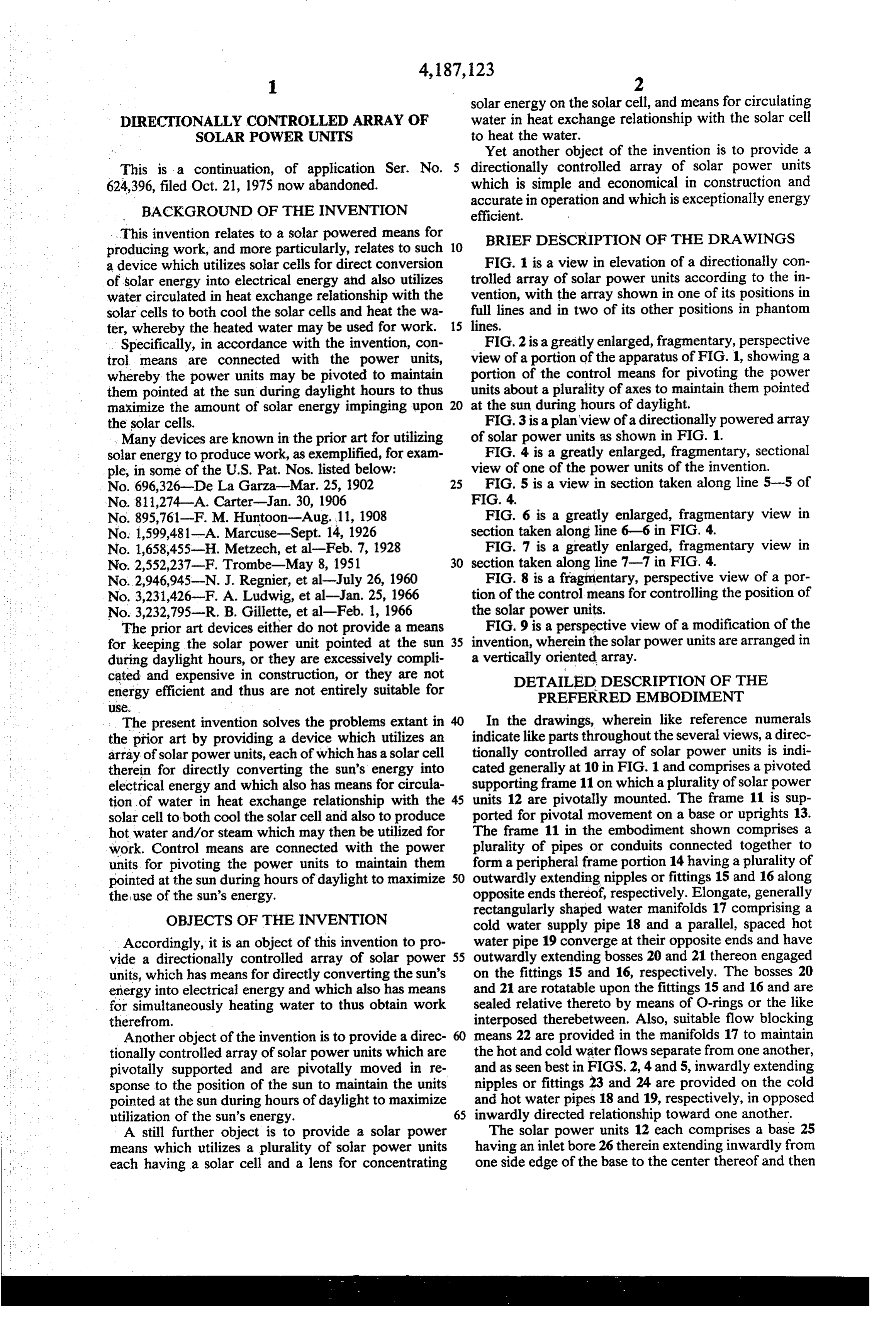
directly upwardly and opening through an upper sur solar array to the various positions at appropriate times face 27 of the base. The inlet bore 26 communicates during the day. The timer could be operative to contin with an outwardly spiraling channel 28 which termi uously move the platform at a slow rate of movement nates adjacent the outer edge of the base in a down during the day, or it could be moved in increments, as wardly projecting outlet bore 29, which terminates at 5 desired.
its lower end in a laterally projecting passage 30 in In addition to pivoting movement of the frame, the diametrically opposed relationship and coaxial with the solar power units are pivotally connected about two inlet bore 26. The fittings 23 and 24 on the water mani mutually perpendicular axes, as noted previously, and folds are rotatably received in the bores or passages 26 as seen best in FIG. 2, this is accomplished by pivoting and 30 and are sealed relative thereto by means of O O movement of the water manifolds 17 about the bosses 20 rings or the like 31. An upstanding, annular wall 32 is on and 21 at their opposite ends. This pivoting movement the upper surface of the base at the outer marginal edge is accomplished by means of a suitable hydraulic cylin thereof, and an annular groove 33 is formed in the upper der or the like 57 connected with an elongate operating surface spaced radially inwardly from the annular wall bar 58 which is pivotally connected in turn with a plu 32. An O-ring or other suitable seal 34 is positioned in 15 rality of upstanding brackets 59 rigidly secured to the the groove 33, and a disc-shaped solar cell 35 is posi manifolds 17, whereby upon extension and retraction of tioned on the upper surface of the base 25 in overlying the piston and cylinder 57 the bar 58 is reciprocated relationship to the spiral passage 28 and the O-ring 34, back and forth, thus rocking the arms 59 and causing the and is sealed relative to the base by means of the O-ring. manifolds to pivot back and forth about the axes of A substantially frusto-conically shaped solar concen 20 fittings 15 and 16 at opposite ends of the frame. Also as trator 36 is supported on the base and has a radially noted previously, the solar power units 12 are mounted inturned flange 37 on its lower end, which is bolted to for pivotal movement about the axes of fittings 23 and the upstanding peripheral wall 32 by means of bolts or 24, and in order to accomplish this movement, a hy cap screws or the like 38, and the inwardly extending draulic cylinder 60 is connected with a link 61 which is flange overlies the outer peripheral edge portion of the 25 connected in turn with a crossbar 62 which has con solar cell 35 to clamp it securely downwardly against nected thereto a plurality of elongate actuating rods 63 the O-ring seal 34. A groove or channel 39 is formed in extending the length of the frame and pivotally con the upstanding annular wall 32 at one side of the base nected to each solar power unit 12 at one side thereof by 25, and a suitable insulated electric lead 40 is disposed in means of a projecting lug 64 on the upper end portion of the channel and has its inner exposed end 41 soldered or 30 the frusto-conically shaped solar concentrators 36. A otherwise suitably secured in electrically conductive similar crossbar 65 is connected across the actuating relationship with the undersurface of the solar cell 35. rods 63 at the end of the frame opposite the cylinder 60. Similarly, at the diametrically opposite side of the solar Thus, the solar power units are effectively ganged to power unit 12 the inturned flange 37 of the concentrator gether for movement in unison upon actuation of the or cone 36 has an upwardly deformed portion 42 therein 35 piston and cylinder assemblies 57 and 60. Cylinders 57 defining a channel in which another electrical conduc and 60 are controlled in response to the position of tor 43 is disposed, with its inner end 44 soldered or solenoid valves 66 and 67, respectively, which are con otherwise suitable secured in electrically conductive trolled, in turn, by means of dummy solar power units relationship with the upper surface of the solar cell 35. or solenoid control cones 68 and 69, respectively, each A suitable lens 45 is suitably secured in the upper end of which has a frusto-conically shaped concentrator 36, of the frusto-conical concentrator 36 for concentrating just as in the solar power units 12, and a base 25. How the sun's rays on the solar cell 35. ever, rather than the solar cells 35, these units 68 and 69 The frame 11 is supported for pivotal movement have suitable thermocouples or the like 70 properly about its longitudinal axis by means of trunnions or the spaced and positioned in the base 25 thereof and a like 46 and 47 suitably rotatably supported in journals or 45 shadow casting element 71 is suitably supported by bearings 48 and 49 at the opposite ends of the frame means of a spider or the like 72 at the upper end of the medially the opposite sides thereof, respectively. Thus cone 36, such that in a normal proper position with the the frame 11 and the solar power units 12 carried cone pointed directly at the sun, all of the thermocou thereby are pivotal about the longitudinal center axis of ples 70 are in the shadow of the unit 71. However, the frame to a plurality of positions, as seen in FIG. 1. 50 whenever the cone 36 is not pointed directly at the sun, As illustrated in full lines, the frame and the solar power one or the other of the thermocouples will not fall units are shown in a position pointed at the sun during within the shadow of member 71 and will thus be ener early morning, for example, and in phantom line at 10a, gized by the sun to cause operation or energization of the frame and solar power units are shown in a position the solenoids 66 and 67 in an appropriate direction to pointed at the sun at noontime, for example, and as 55 cause the cone to be pointed at the sun. shown in phantom line at 10b, the array is shown in a Thus, the directionally controlled array of solar position whereat the solar power units are pointed power units according to the invention is automatically toward the sun in the evening. positioned in response to movement of the sun in order A hydraulic cylinder 50 or other suitable means is to maintain the solar collectors or cones thereof pointed supported on a bracket or the like 51 on the uprights or directly at the sun at all times during daylight hours to base 13 and is connected with the frame 11 for moving maximize utilization of the sun's energy. Moreover, the the frame to its several pivoted positions, as shown in heat energy generated from the solar-cells is utilized to FIG. 1. A suitable solenoid valve or the like 52 is con heat water to produce either hot water or steam, de nected via a pair of supply conduits 53 and 54 with the pending upon the temperatures attained, and this heated cylinder 50 for controlling flow of water or other hy 65 water or steam may thus be utilized for work. draulic fluid thereto from a supply pipe 55. A suitable In FIG. 9 a modification of the invention is shown, timer mechanism 56 is connected with the solenoid and in this form of the invention a pair of upstanding valve 52 for operating the valve to move the frame and masts or posts 73 and 74 comprise a frame in which the
Page 8
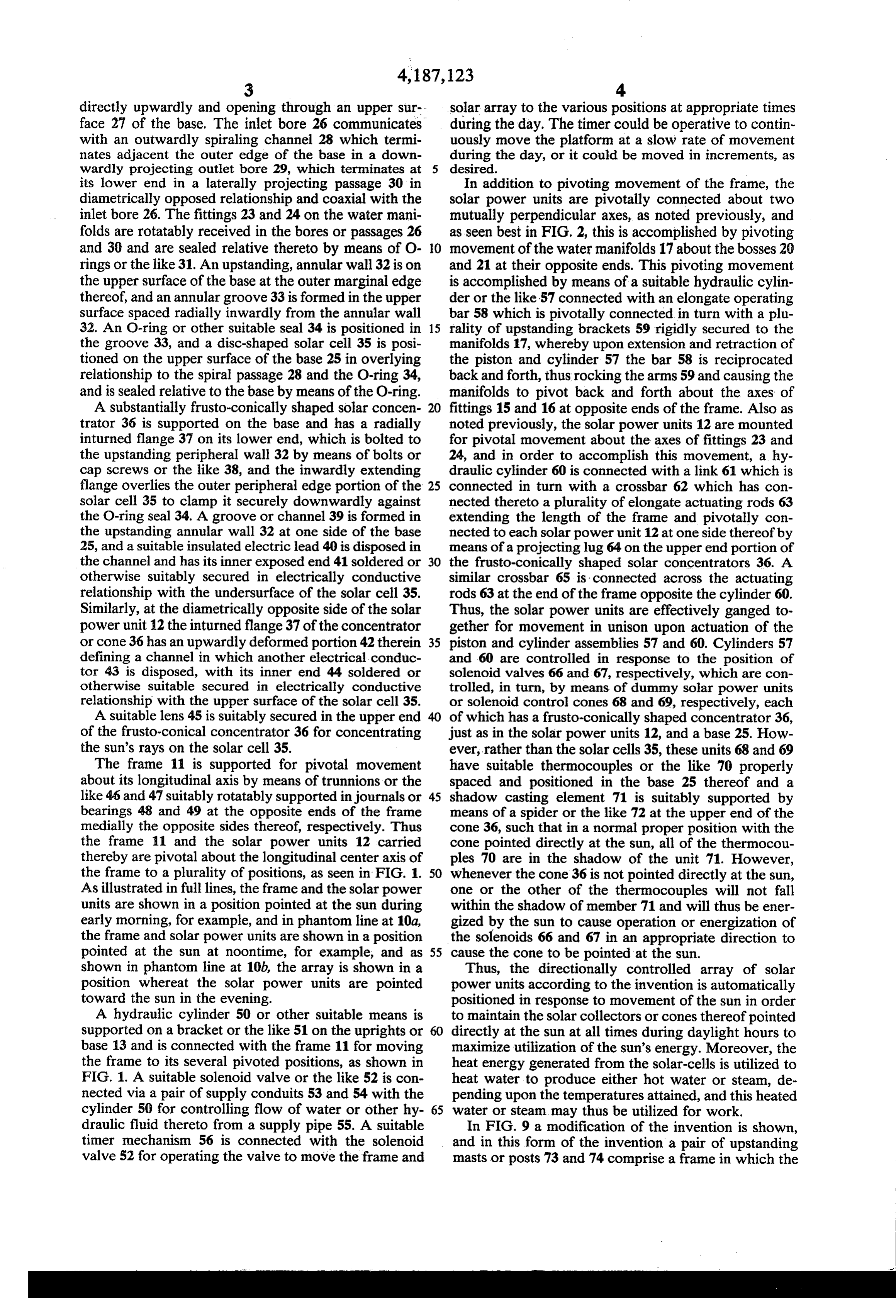
plurality of manifolds 17 are pivoted for supporting the the sides of the frame and substantially coextensive in solar power units 12 in a manner similar to that de length therewith, said pipes converging at their oppo scribed in relation to FIGS. 1-8. The solar cells 35 in site ends and having projecting fittings thereon rotat the solar power units 12 may be suitably electrically ably received in cooperating bosses on confronting connected with a plurality of batteries or the like 75, if 5 inner surfaces of the opposite ends of the frame, desired, for storing the electrical energy produced whereby said hot and cold pipes are disposed in pairs thereby for use during hours of darkness. The heated and are pivotally supported at opposite ends of the water or steam produced as a result of cooling the solar frame for pivotal movement about axes extending paral cells may be utilized to operate a steam driven electrical lel to the pivotal axis of the frame. generator or the like 76, if desired. 3. A solar array as in claim 1, wherein said control As noted previously, the piston and cylinder assem 10 means includes a plurality of thermocouple means, blies may be driven or operated by means of the water means spaced from the thermocouple means normally supplied to the hydraulic system of the invention, or, if shading the thermocouple means, said thermocouple desired, they may be operated by means of oil or other means supported in a housing carried by the frame and suitable motive fluid. For example, they could be pneu movable with the power units, whereby the housing is matically operated, if desired. 15 oriented identically to the orientation of the power It is apparent that a directionally controlled array of units, and power means connected with the frame and . . solar power units in accordance with the invention power units and responsive to energization of the ther could be provided with hundreds of power units to thus mocouple means to pivot the frame and power units to produce large amounts of power in a relatively small maintain the power units pointed at the sun and to main amount of space, particularly in view of the use of 20 tain the thermocouples in the shade. lenses 45 to concentrate the sun's energy on the solar 4. A solar array as in claim 2, wherein power means cells 35. is connected with the frame and with the power units As this invention may be embodied in several forms for pivoting the frame and power units to maintain the without departing from the spirit or essential character power units pointed at the sun during hours of daylight, istics thereof, the present embodiment is, therefore, said power means comprising hydraulic piston and cyl illustrative and not restrictive, since the scope of the 25 inder assemblies and link means connected between the invention is defined by the appended claims rather than by the description preceding them, and all changes that piston units and cylinder assemblies and the frame and power to pivot the frame and power units in response to fall within the metes and bounds of the claims or that form their functional as well as conjointly cooperative extension semblies, and retraction of the piston and cylinder as said control means comprising solenoid valves
equivalents are, therefore, intended to be embraced by connected between those claims. the pipes of the frame for receiving I claim: water therefrom and the piston and cylinder assemblies 1. A directionally controlled array of solar power for the controlling flow of water from the frame pipes to piston and cylinder assemblies.
units, comprising: a pivotal supporting frame; a plural 5. A solar array as in claim 4, wherein said control ity of solar power units pivotally mounted on the frame 35 means comprises a housing mounted on the frame for for pivotal movement about two mutually perpendicu movement in unison with said power units, a plurality of lar axes; conduit means on the frame for flow of cold water to and hot water from each power unit; each thermocouple means carried by the housing means and means carried by the housing means for shading the power unit including a solar cell for direct conversion thermocouple of solar energy into electrical energy; lens means on power units aremeans when the housing means and each power unit arranged to concentrate solar energy when the powerpointed directly at the sun, such that on the solar cell of that unit; said conduit means con pointed directly at the sun, onehousing units and or more means are not of the thermo nected for flow of cold water in heat exchange relation ship with the solar cells to cool the solar cells and heat couple means is exposed to the sun to thus energize the the water, said hot water thus being available for work; 45 solenoid valve means to operate the piston and cylinder each power unit further comprising a base having a top to maintaintothem assemblies orient the power units and housing means pointed at the sun.
surface and a bottom surface, an inlet into said base and extending through said base and exiting outwardly are6.electrically A solar array as in claim 1, wherein the solar cells connected with a plurality of storage through the top surface of the base, a serpentine, open batteries for storing electrical energy produced thereby fluid flow troughlike passageway defined in said base during hours of daylight for subsequent use of the elec top surface and extending from the inlet and a passage 50 extending from the passageway downwardly into the trical energy during hours of darkness.
base and thence outwardly through said base, said solar 7. A solar array as in claim 6, wherein the hot water cell overlying the passageway closing the open side outlet from the power units is connected with suitable thereof to confine fluid flow through the passageway power means for producing work.
with said fluid contacting one side of said solar cell; and 55 8. A solar circular, array as in claim 5, wherein said base is control means connected with the power units and the substantially and said inlet is defined on one frame to pivot the power units in response to the posi side thereof and exits upwardly at the center thereof, tion of the sun to keep the power units pointed at the and further wherein said fluid flow passageway is spiral sun during hours of daylight. shaped and has an exit passage adjacent the outer pe 2. A solar array as in claim 1, wherein the supporting 60 riphery of said base located diametrically opposite said frame is rectangular in shape and includes opposite ends inlet, and further including a conically-shaped solar and opposite sides, said frame comprising a plurality of concentrator supported on the base above the solar cell joined together, elongate pipes, outwardly extending and having lens means carried thereby for concentrat journals on the pipes at the opposite ends of the frames ing the sun's energy on the solar cell to produce electri medially of the opposite ends supported in bearing cal energy therefrom, said cold water pipe connected means for pivotal movement of the frame from side to 65 with the inlet to the base for circulation of cold water side about the longitudinal axis thereof, said conduit into the base and through the spirally-shaped passage means including a plurality of pairs of spaced apart, way to heat the water. k it sk parallel hot and cold water pipes extending parallel to
Provenance
- Collection
- Cited prior art
- Original PDF
- patentimages.storage.googleapis.com →
- Filed
- 1977-11-15
- Pages
- 8
- Method
- pdftotext (the PDF's own text layer) + pdftoppm 300dpi page scans
- Source
- Google Patents bibliographic record
- Granted
- 1980-02-05
- Inventors
- Richard E. Diggs
- Transcribed from
- patentimages.storage.googleapis.com →