patent · US2249642
Solar power apparatus
15 July 1941
Page 1
Drawing sheet — no readable text.
Page 2
Patented July 15, 1941 2,249,642
soLAR POWER APPARATUS
Jedward T. Turier, Dayton, Ohio
Application January 27, 1938, Serial No. 187,253
This invention relates to an apparatus for tional heater may be of any desired size and utilizing solar heat to develop power. shape and they may conveniently be rectangular One object of the invention is to provide a in shape and of a width of approximately one solar heater of simple construction which will foot and of a length of approximately fifteen feet. have high efficiency. The tubes may be of relatively thin copper of Afurther object of the invention isto provide a tº one-eighth of an inch diameter and in the par ticular arrangement here shown I have employed
Solar heater of simple construction which will heat Water under pressure substantially to its straight tubes and have spaced the same laterally temperature of vaporization. - One from the other a distance of about two To this end it is a further object of the inven inches. The tubes extend for substantially the full length of the base and the several tubes of tion to provide a solar heater having a large heat each Section are connected at one end of the absorbing capacity and Small heat radiation. base with an inlet header 2 which in turn is A further object of the invention is to provide Connected by a tube í 3 to a supply pipe Í4 for a solar heater comprising a series of Sections or Water under pressure. At the other end of the units, any number of which may be assembled in base the several tubes are connected with an out a single heater to provide the same with the de let header 5 which is connected by a tube 6 sired capacity. With a discharge conduit ii. In the particular A further object of the invention is to provide construction here illustrated this discharge con means for storing the heated water and main duit is of large capacity and serves both as a dis taining the same at a high temperature and a charge conduit and as a storage chamber for the high pressure. heated Water and for this purpose it is provided A further object of the invention is to provide With a covering 8 of insulating material. A means for utilizing the heated water in the gen transparent cover 9, preferably in the form of a eration of power. vn
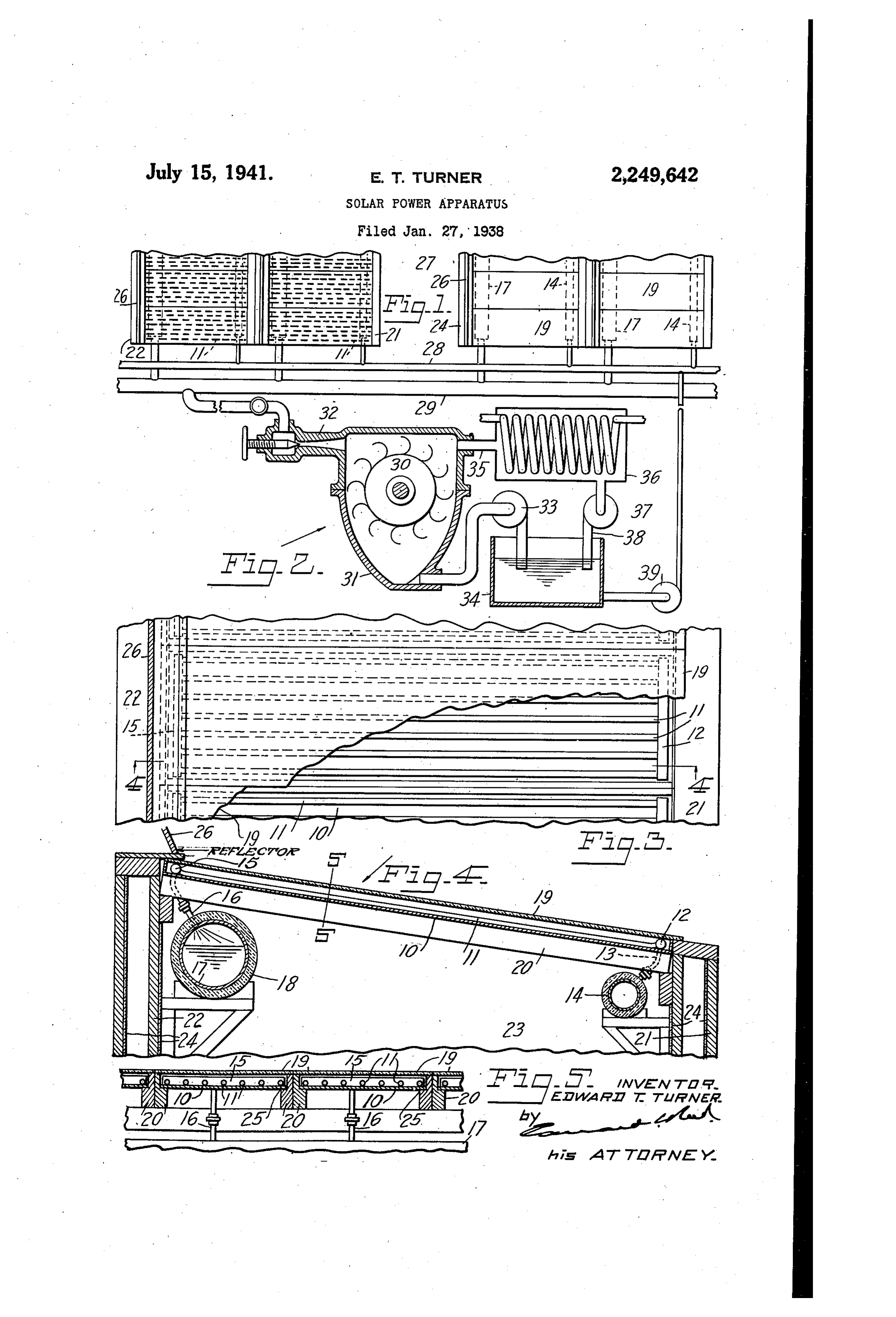
Other objects of the invention may appear as 2. sheet of glass, is arranged above and in spaced re lation to the tubes. The base and the transparent the apparatus is described in detail. Cover may be Supported in any suitable manner. In the accompanying drawing Fig. 1 is a plan view of a portion of a solar heating apparatus tionthe In present construction the base of each sec comprising a plurality of heaters; Fig. 2 is an ele 30 rails is2 Supported at its lateral edges on parallel vation, partly in section, of a power apparatus 3 Suitable Supporting Supported which are structure, at their ends on a in a more or less to be actuated by water heated by said heater; elevated position. Preferably this supporting Fig. 3 is a plan view, partly broken a Way, of one Structure is in the form of a housing comprising of the heaters of said heating apparatus; Fig. 4 is a sectional view taken on the line A-4 of Fig. Side Walls 2 f and 22, on which the respective ends 3; and Fig. 5 is a section taken through a portion of the rails are supported, and end walls 23. The Walls of this supporting structure are preferably of said heater on the line 5-5 of Fig. 4.
In the drawing I have shown, by Way of illus insulated against the transmission of heat, as by tration, one embodiment of my invention in providing the same with one or more layers of heat insulating material 24. In the arrangement
Which the heater comprises a series of Separate 40 shown, sections or units, any number of which may be the rails 20 are provided with shoulders assembled in a single heater to provide the latter 25 (Fig. 5). On which the base plate rests and each rail extends upwardly beyond that shoulder to with the desired capacity for hot water. It will Support be obvious, however, that the invention may be the glass cover 9 above the tubes. The embodied in a single unit of such size as to pro Supporting Structure is preferably of a substan vide the desired heating capacity. 45 tial length and is adapted to receive and support This heater, and each section of a sectional a Series of Sections, as shown in Fig. 5, the sec heater, comprises a base 9 of heat absorbing tion tions being arranged edge to edge in close rela material, such as copper, and Supported by this one to the other so as to form a closure for the top of the Supporting structure. While I have base and in heat receiving relation thereto is a 50 here series of Small tubes which are preferably shown a separate glass cover for each section mounted directly upon and secured to the base, it Will be obvious that a single plate of glass could as by soldering. The tubes may be supported on be arranged above two or more of these sections either the upper surface or the lower Surface of and When this is done those portions of the inter the base but are here shown as mounted on the 55 mediate rails 20 above the shoulders 25 may be upper surface. The individual sections of a sec Omitted or may be of such a character as to
Page 3
merely support the glass without preventing open reservoir is greatly reduced in quantity. The communication between the adjacent sections. lower surface of the base 0 will radiate some In either arrangement the tubes of the Section heat to the air within the Supporting structure or sections are enclosed in a housing formed and this air will be heated, but the hottest air between the base and the cover, closed at its sides will rise to the top of the structure in contact by the upper portions of the rails and closed at with the base and there Will be but little loSS of its ends by the side walls 2 and 22 of the Sup heat due to this radiation. porting structure. In a large capacity heater it will usually be Each section of the heater is preferably in desirable to provide a plurality of series of Sec clined so that the tubes thereof Will slope up tions, each series being carried by a separate Wardly from the inlet header 2 to the Outlet supporting structure. In order that each series header 5, this inclination being secured in the of heating units may be readily accessible the arrangement shown by making the one wall, 2f, several series may be arranged in pairs, as shown of the supporting structure of less height than in Fig. 1, and the adjacent pairs spaced one from the other wall, 22. By so sloping the Several the other to provide between then passageWays sections, or heating elements, of the heater the 2. With this arrangement the Water Supply air which is confined about the tubes Within the conduits i4 of the several Series of Sections Would housing, as it becomes heated, will move upward be connected with the source of water supply by ly toward the upper end of the section where means of a main conduit 28, and the discharge the tubes and the water therein are at the high 20 conduits f of the several Series of sections WOuld est temperature, thus minimizing radiation at be connected with a conduit 29 leading to the the lower portion of the section and increasing point of use.
the efficiency of the unit. This sloping arrange In the present embodiment of the invention ment of the sections also enables the water to be moved slowly and uniformly through the 25 the water, which is delivered from the heater at high temperature and high pressure, is utilized tubes and, further, it permits of the heater be in the operation of power apparatus. This ap ing so arranged that the sun's rays will be ap paratus may be of any suitable type and that proximately perpendicular to the surface there here illustrated is substanially similar to the of throughout a substantial portion of the day.
If desired, a reflector 26 may be arranged at the 30 power apparatus shown and described in my co pending application for patent filed January 27, upper end of the heater to reflect additional 1938, Serial No. 187,252, this apparatus compris rays of the sun onto the upper part of the heater ing a power element, such as a Pelton wheel 30, and thus impart additional heat to the water at which is mounted in a casing 3i, and the con the place it is to be raised to the highest ten duit 29 Winich leads from the Several discharge perature and where the radiation is greatest. 35 and storage conduits í 1 is connected with this The base and the tubes themselves Will both casing by means of an expansion nozzle 32. absorb heat from the sun's rays and the heat When the water at high temperature and high absorbed by the base will be conducted to the pressure is passed through this nozzle 32 a. por-º tubes to further heat the same. Both the base 40 tion of the water is converted, or flashed, into and the tubes are preferably covered with a suit-, steam and the steam is expanded and mixed able substance, such as lamp black, which will with the Water to convert heat and pressure increase their absorbing capacity and will mini energies into Velocity energy, so that the mixture mize radiation. It is not essential that the tubes of water and steam Will be discharged from the should be exposed to the Sun's rays and when In Ozzie with a velocity energy Sufficient to oper arranged beneath the base they will receive heat 45 ate the power element. After having acted upon from the base by conduction. As a result of the power element the Water and Steam may be this arrangement the Water as it moves slowly disposed of in any suitable manner but prefer through the tubes, under pressure, will accumu ably they are recovered and again returned to late heat in substantial quantities, so that it may be discharged through the Outlet header 50 the the heater for use. In the arrangement shown, water is Withdrawn from the lower portion 8 at a temperature approximating its tempera of the casing 3, as by means of a pump 33, and ture of vaporization. The Water thus discharged delivered to a low preSSure reservoir or tank 34. from the heating elements at high temperature The steam is withdrawn from the upper portion and high pressure is conducted through the dis of the casing through an outlet conduit 35 and charge conduit 7, or through any other Suitable 55 delivered to a condenser 36. The condensate is channel, to the point of use. Any suitable res ervoir may be provided for storing the heated withdrawn from the condenser, as by means of a pump 37, and delivered through a conduit 38 water under pressure until needed and by uti to the reservoir 34. The condensate and with lizing the discharge conduit as a storage reser dra Win Water are stored in this reservoir and, as voir this storage is effected with a minimum of 60 required, are withdrawn therefrom by a pump 39 loss of heat, due not only to the insulation of Which is connected by the main Water conduit the conduit itself but due also to the fact that 28 with the supply conduits 4 of the several the conduit is enclosed within the supporting Series of heating elements. Thus the same water structure and there is no circulation of air about may be utilized over and over again, with the the same. The water entering the reservoir will 65 addition of only So much Water as is required to be partially vaporized so that the Water in the compensate for losses.
reservoir Will be under the pressure of the Steam, It will be understood that the water from the which Will accumulate in the upper portion of heater is stored in the storage conduit, or other the reservoir. If water is withdrawn from the 70 receptacle, while the sun is shining and will be reservoir faster than it is supplied thereto a raintained at high temperature and high pres slight reduction in pressure will result and cause sure for a substantial period of time after the the vaporization of additional water and the Sun has ceased to shine and is thus available to pressure will be substantially maintained. Thus operate the power apparatus at night or during the water will be maintained at a substantially 75 cloudy intervals. The water and condensed steam constant pressure even though the Water in the are Stored in the low pressure tank 34 and are
Page 4
available for use when needed. The pump. 39 to said tubes at one end of said base, an insu which returns the Water and condensate to the lated storage receptacle arranged within said heater Will be operated only when the Sun is housing, and means for connecting said recep tacle with said tubes at the other end of said
Shining, and at such times as the sun is not 5 base.
Shining, and the pump is not operating, the water 2. In a Solar heating apparatus, a housing hav and condensate will merely accumulate in the ing upright Walls closing the sides and ends tank and will be stored therein for future use. thereof, a heater Supported by said housing and While I have shown and described one embodi comprising a plurality of Sections, each section ment of my invention I wish it to be understood including a base of heat absorbing material, a that I do not desire to be limited to the details 10 of the same as various modifications may occur plurality of tubes Supported in heat receiving relation to said base, inlet and outlet headers to a person skilled in the art. connected with the respective ends of said tubes, Having now fully described my invention, and a transparent closure, the bases of said sec what I claim as new and desire to secure by Let ters Patent, is: 5 tions being supported side by side by the side 1. In a Solar heating apparatus, a housing hav Walls of Said housing and forming a closure for ing upright walls closing the sides and ends Said housing, a Supply conduit connected with thereof, a heater comprising a base of heat ab the inlet headers, and a combined discharge and Sorbing material, a plurality of tubes supported storage receptacle supported within said hous in heat receiving relation to said base, and a 20 ing, extending lengthwise thereof and connected with Said outlet headers.
transparent closure above said base, said heat absorbing base extending across and closing the EDWARD T. TURNER. top of the housing, means for supplying water
Provenance
- Collection
- Cited prior art
- Original PDF
- patentimages.storage.googleapis.com →
- Filed
- 1938-01-27
- Pages
- 4
- Method
- pdftotext (the PDF's own text layer) + pdftoppm 300dpi page scans
- Source
- Google Patents bibliographic record
- Granted
- 1941-07-15
- Inventors
- Edward T Turner
- Transcribed from
- patentimages.storage.googleapis.com →