patent · US1599481
Solar heater
14 September 1926
Page 1
Drawing sheet — no readable text.
Page 2
Drawing sheet — no readable text.
Page 3
Patented Sept. 14, 1926. 1,599,481
UNITED STATES PATENT OFFICE.
ADOLF MARCUSE, OF CHARLOTTENBURG, NEAR BERLIN, GERMANY.
SOLAR HEATER.
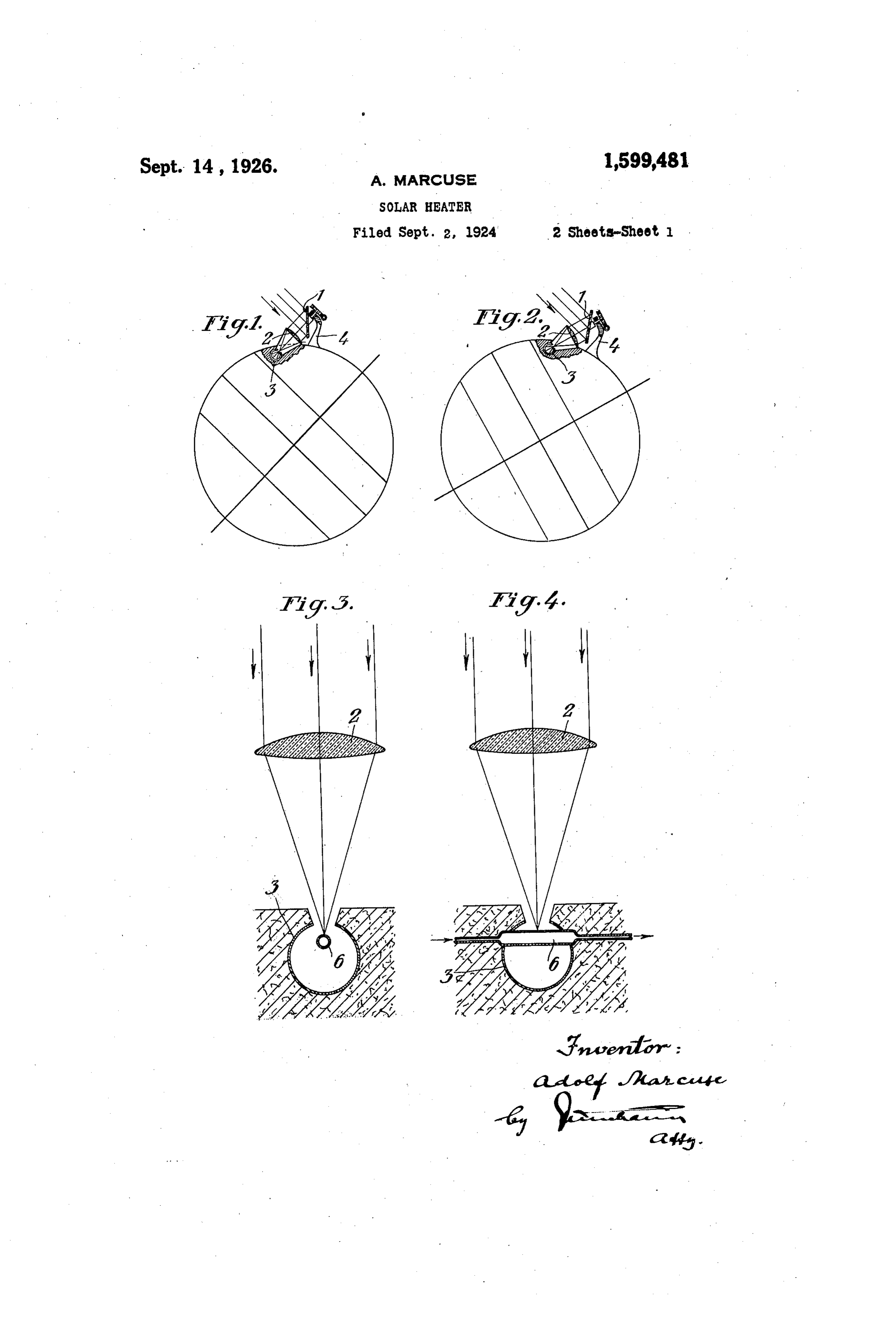
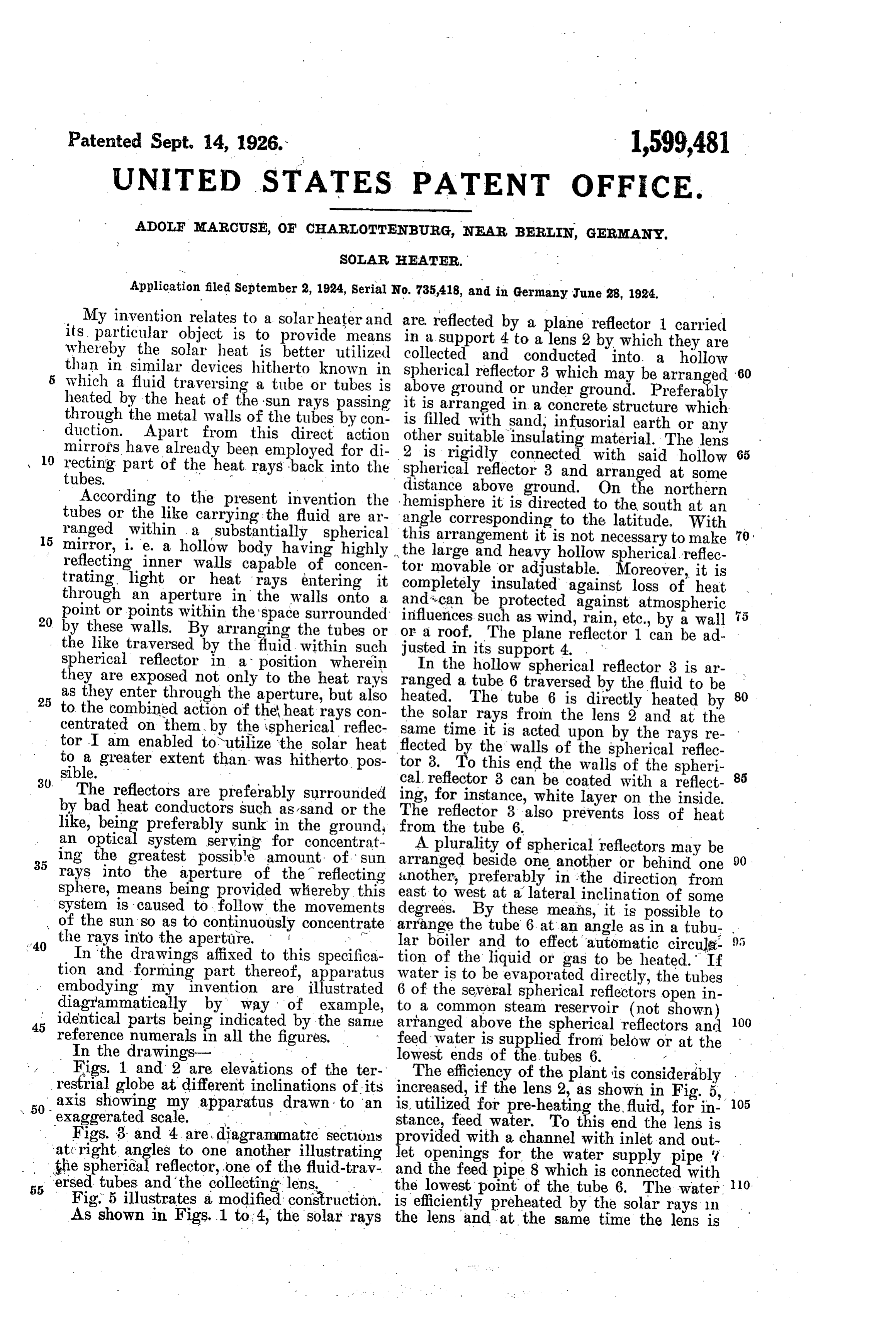
Application filed September 2, 1924, serial No. 735,418, and in Germany June 28, 1924. My invention relates to a solar heater and are reflected by a plane reflector 1 carried its particular object is to provide means in a support 4 to a lens 2 by which they are whereby the solar heat is better utilized collected and conducted into a hollow than in similar devices hitherto known in
which a fluid traversing a tube or tubes is spherical reflector 3 which may be arranged 60 heated by the heat of the sun rays passing it is arranged orin under above ground
ground. Preferably concrete structure which through the metal walls of the tubes by con is filled with sand, infusorial earth or any duction. Apart from this direct action other suitable insulating material. The lens mirrors have already been employed for di 10 recting part of the heat rays back into the 2 is rigidly connected with said hollow 65 tubes. spherical reflector 3 and arranged at some distance
According to the present invention the hemisphere above ground. On the northern tubes or the like carrying the fluid are ar angle corresponding it is directed to the south at an ranged within a substantially spherical this arrangement it istonotthenecessary latitude. With
mirror, i. e. a hollow body having highly the large and heavy hollow sphericaltoreflec make to reflecting inner walls capable of concen trating light or heat rays entering it tor movable or adjustable. Moreover, it is through an aperture in the walls onto a and can be insulated completely protected against loss of heat against atmospheric point or points within the 'space surrounded 20 by these walls. By arranging the tubes or influences such as wind, rain, etc., by a wall 5 the like traversed by the fluid within such or a roof. The plane reflector 1 can be ad justed in its support 4. .
spherical reflector in a position wherein In the hollow spherical reflector 3 is ar they are exposed not only to the heat rays ranged as they enter through the aperture, but also heated. a The 25 to the combined action of the heat rays con the tube 6 traversed by the fluid to be 80 tube 6 is directly heated by centrated on them by the spherical reflec same time it is from solar rays the lens 2 and at the tor I am enabled to utilize the solar heat flected by the walls ofupon acted the by the rays re spherical reflec to a greater extent than was hitherto pos tor 3. To this end the walls of the spheri 30. sible. - cal reflector 3 can be coated with a reflect 85 The reflectors are preferably surrounded ing, for instance, white layer on the inside. by bad heat conductors such as sand or the The reflector 3 also prevents loss of heat like, being preferably sunk in the ground from the tube 6.
an optical system serving for concentrat A plurality of spherical reflectors may be ing the greatest possible amount of Sun arranged beside one another or behind one 90 rays into the aperture of the reflecting another, preferably in the direction from sphere, means being provided whereby this east to west at a lateral inclination of some system is caused to follow the movements degrees. By these means, it is possible to of the sun so as to continuously concentrate arrange the tube 6 at an angle as in a tubu the rays into the aperture. lar boiler and to effect automatic circula. In the drawings affixed to this specifica tion of the liquid or gas to be heated. If tion and forming part thereof, apparatus water is to be evaporated directly, the tubes embodying my invention are illustrated 6 of the several spherical reflectors open in diagrammatically by way of example, to a common steam reservoir (not shown) 45 reference parts identical being indicated by the Sale arranged above the spherical reflectors and 100 numerals in all the figures. m feed water is supplied from below or at the In the drawings lowest ends of the tubes 6.
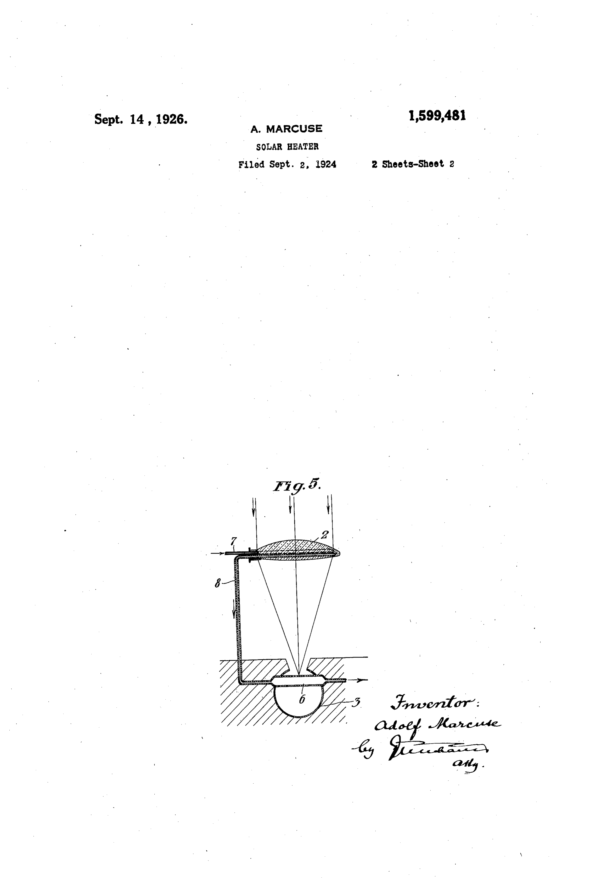
Eigs. 1 and 2 are elevations of the ter The efficiency of the plant is considerably restrial globe at different inclinations of its increased, if the lens 2, as shown in Fig. 5, 105 50 axis showing my apparatus drawn to an is utilized for pre-heating the fluid, for in
Figs. 3 and 4 are diagrammatic sectlyns providedstance, feed water. To this end the lens is at right angles to one another illustrating let openings with a channel with inlet and out for the water supply pipe the spherical reflector, one of the fluid-trav and the feed pipe 8 which is connected with 0. 55 ersed tubes and the collecting lens, the lowest point of the tube 6. The water. Fig. 5 illustrates a modified construction. is efficiently preheated by the solar rays in As shown in Figs. 1 to 4, the Solar rays the lens and at the same time the lens is
Page 4
cooled. By these means stresses in the lens the solar rays entering it through said ap and loss of the available solar energy are erture and optical means for directing solar 20 avoided. rays into said reflector. Obviously collecting lenses and cylindri 2. Solar heater comprising fluid carrying cal reflectors may also be used in connec means, a hollow substantially spherical re tion with apparatus in which the object is flector having an aperture therein and sur 25 heated merely by convection. rounding Said fluid carrying means so as to I wish it to be understood that I do not concentrate thereon a large proportion of desire to be limited to the exact details of the solar rays entering it through said ap 10 construction shown and described, for ob erture, optical means for directing solar vious modifications will occur to a person rays into said reflector and means whereby the fluid to be heated is enabled to first 30 skilled in the art. a
I claim :- traverse said optical means so as to be pre 1. Solar heater comprising fluid carrying heated therein and to exert a cooling effect 15 means, a hollow substantially spherical re thereon.
flector- having an aperture, therein and sur In testimony whereof I affix my signature. rounding said fluid carrying means so as to concentrate thereon a large proportion of ADOLF MARCUSE.
Provenance
- Collection
- Cited prior art
- Original PDF
- patentimages.storage.googleapis.com →
- Filed
- 1924-09-02
- Pages
- 4
- Method
- pdftotext (the PDF's own text layer) + pdftoppm 300dpi page scans
- Source
- Google Patents bibliographic record
- Granted
- 1926-09-14
- Inventors
- Marcuse Adolf
- Transcribed from
- patentimages.storage.googleapis.com →