patent · US3104210
Solar stills
17 September 1963
Page 1
Drawing sheet — no readable text.
Page 2
Drawing sheet — no readable text.
Page 3
United States Dffice 3,104,210 Patented Sept. 17, 1963
spreading the water to be heated as a thin layer and 3,104,20 preferably comprise a sheet of capillary material, such
S3LAR STLLS
Wadsworth W. Mount, Summit, N.J., assignor of nine and as black cotton cloth, to which the water is slowly fed eightiefiths percent to each of the following: James L. by capillarity from a water reservoir below the sheet. Buckey, Aloise B. Heatin, Soian W. Buckley, Prisci: a Other means are provided for rinsing the sheet with fresh Bickley, Jane B. Smith, William F. Buickley, Jr., quantities of the impure water from time to time, and pref atricia B. Bozweil, Fergus R. Buckley, Maureer erably at night or during times when the sun is obscured, Buckley, and Connecticut Bank & Trist Co., guardian So that any deposits of salt on the sheet are reduced
the estate of Carol Buckley, to C. Dean Reasoner and a two percent or removed before they seriously interfere with the opera
Criginal application May 10, 1952, Ser. No. 287,501, now 10 tion of the still. In one form, the sheet is positioned and the vessel is so formed that the level of the salt water
Patent No. 2,843,536, dated Jay 5, 1958. Divided may be raised to the level where the sheet is submerged and his application May 2, 1958, Ser. No. 732,540 in the salt water used for rinsing, thereby allowing the
rinsing water to dissolve out the salts as it flows over
The present invention relates to new and useful im the sheet and into the salt water drain portion of the provements in the Solar distillation of sea water and the vessel.
like to produce fresh or relatively pure water. The feed water is preferably stored in a reservoir hav Objects and advantages of the invention will be set ing a relatively large area and is covered with a super forth in part hereinafter and in part will be obvious here natant layer of radiation absorbing, immiscible material, from, or may be learned by practice with the invention, 20 Such as black oil, so that it may be preheated by solar the same being realized and attained by means of the radiation, and is fed from the reservoir as needed to the instrumentalities and combinations pointed out in the ap Several Solar stills.
pended claims. In actual practice, the apparatus may be spread over The invention consists in the novel parts, constructions, large areas, such as several acres, comprising one or more arrangements, combinations and improvements herein 25 large reservoirs for preheating the water, and a relatively shown and described. large number of interconnected distillation units, from The present application is a division of my prior co which the fresh water is collected into fresh water reser pending application Serial No. 287,101, filed May 10, voirs, while the partially distilled salt feed water is drained 1952, now Patent Number 2,843,536. off, and would ordinarily be returned to the sea or used The accompanying drawings, referred to herein and 30 as a source of concentrated brine.
constituting a part hereof, illustrate one embodiment of It will be understood that the foregoing general de the invention, and together with the description, serves Scription and the following detailed description as well to explain the principles of the invention. are exemplary and explanatory of the invention but are Of the drawings: not restrictive thereof.
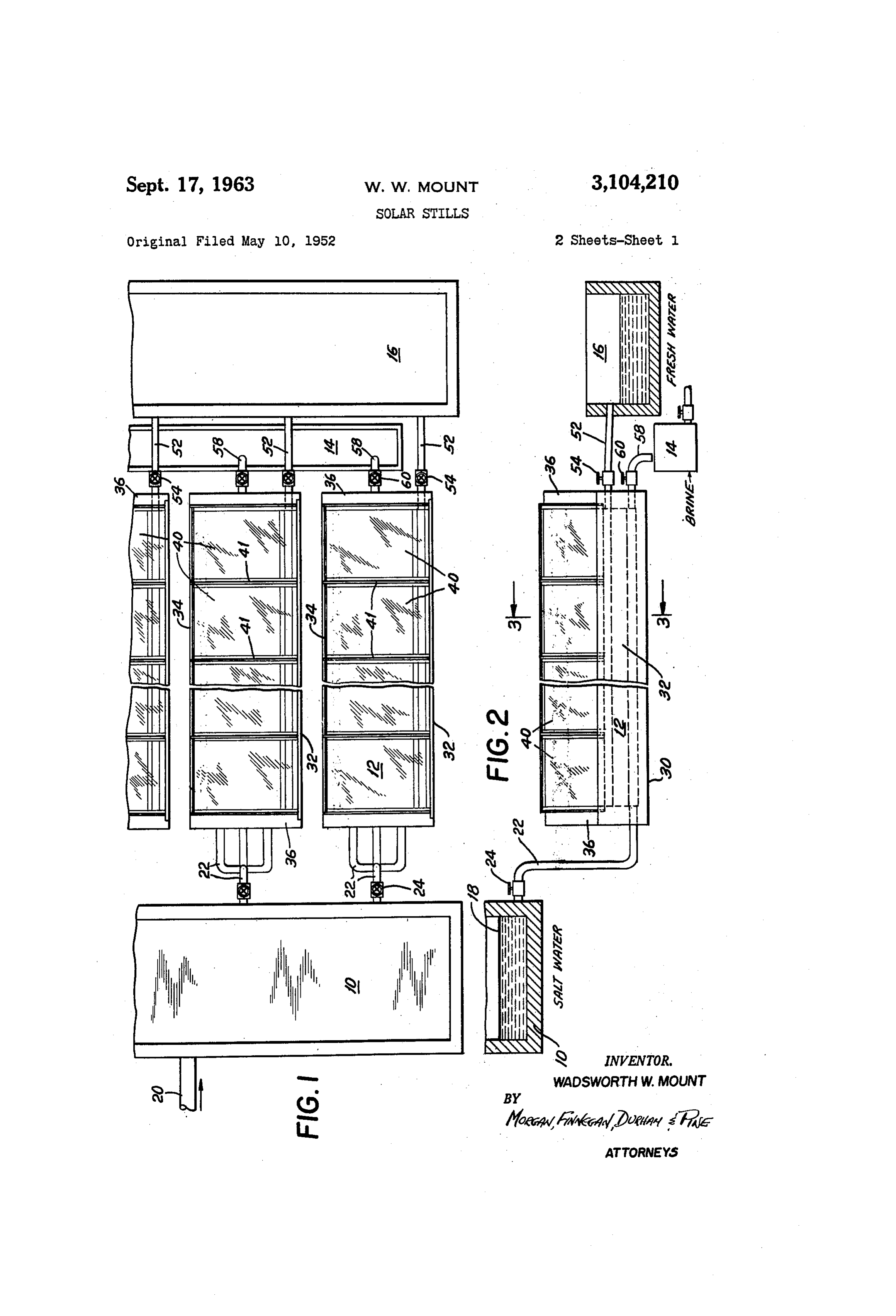
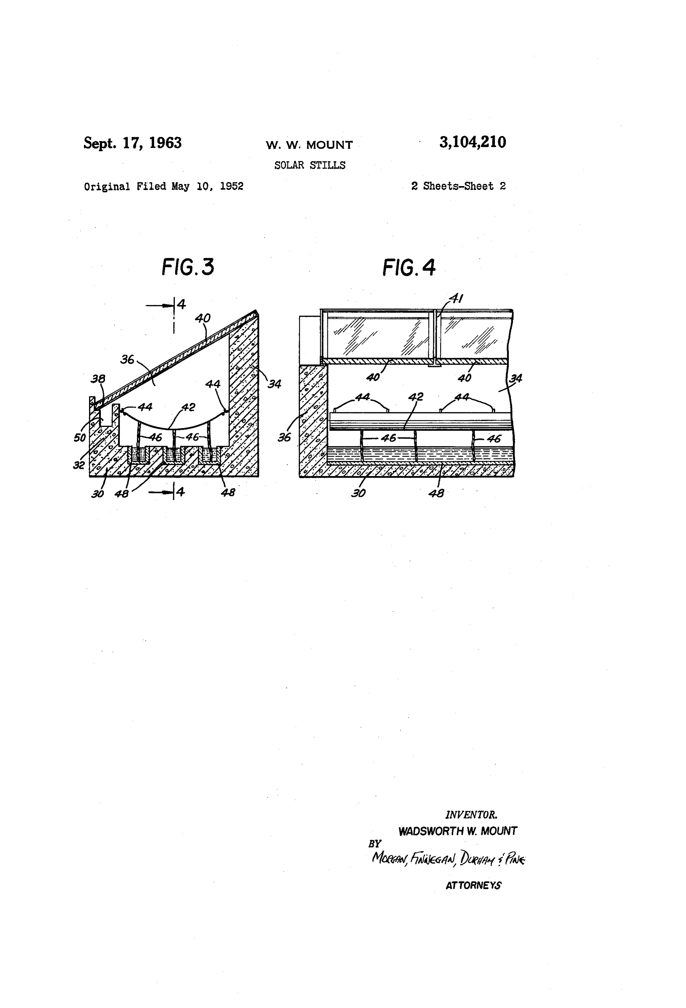
FIGURE 1 is a fragmentary top plan view showing one Referring now in detail to the present preferred and embodiment of the present invention; illustrative embodiment of the present invention as shown FIGURE 2 is a side elevation, partly in section, of the in FIGURES 1 to 4 of the accompanying drawings, there embodiment shown in FIGURE 1; is provided a large reservoir i0, which is connected by FiGURE 3 is a vertical section taken on the line 3-3 piping to feed by gravity to a plurality of distillation units of FIGURE 2; 40 E2, from which the salt water is drained into one or FIGURE 4 is a sectional view taken on the line 4-4 more waste tanks 14, while the fresh or salt-free water is of FIGURE 3. drained into and collected in the fresh water tank 16. The present invention has for its object the provision iThe brine reservoir 19 preferably comprises a shallow of a novel and improved Solar distillation apparatus for 45 tank which is supplied with salt water, brine or other the distillation of fresh, potable water from sea water, water to be purified from the sea or other source through brackish or otherwise contaminated water. A further a pipe 28, the water being pumped into the reservoir 10 object is the provision of a novel and improved apparatus at such a rate that a substantially constant level is main of this kind which is relatively simple and economical tained. In actual practice, the water in the tank 10 is in its construction, and can be operated for long periods 50 preferably about 6 inches deep and should not exceed of time without requiring the expenditure of excessive one or two feet in depth. The tank 10 is preferably labor, and which is especially adapted for large scale constructed of durable waterproof material such as con application. A further object is the provision of apparatus crete or resistant wood, such as cypress, and may have of this kind which can be easily washed to free the ap an area of as much as a few acres. paratus from the excessive accumulations of salt which Preferably, and for the efficient preheating of the water result from continued operation of the apparatus and in the tank 10, there is provided on the surface of the otherwise gradually interfere with its efficient operation. water a thin layer of a heat absorptive material E8 which The apparatus is particularly adapted to be constructed is immiscible with the water and which does not contam of durable, and relatively inexpensive materials of con inate the water. This material is preferably a liquid and struction, and thus can be constructed for relatively small is chosen so as to have a high degree of absorption for cost and for the distillation of whatever quantities of 60 Solar radiation. For this purpose, a dark heavy petro water are to be treated. leum oil, soft still pitch or asphaltum is suitable, and is The present invention provides an efficient apparatus preferably used in a layer not exceeding 4 inch in thick which is adapted to be supplied with a quantity of water ness. Such material forms a thin supernatant layer which contaminated with salts or other impurities, and to hold 65 is in intimate thermal contact with the body of water and this quantity of water in a water-tight and substantially transfers its absorbed heat directly to the water with a air-tight vessel while the water is fed in a thin layer over minimum of loss. Floating sheets of dark or black ma a large area and is exposed to the rays of the sun to heat terial, Such as blackened metal pans may also be used. the water and cause it to evaporate, the water vapor then The preheated water is fed from the brine tank 10 condensing on a relatively cooler surface from which it through distribution pipes 22 to the individual distillation drains by gravity into a collecting drain by which it is 70 units 12, the gravitational flow of the water being regu removed from the vessel and may be conveyed to a tank lated by ineans of the valves 24, so that the rate of feed or other storage receptacle. Means are provided for is normally two to four or five times or only slightly in
Page 4
es 4.
excess of the rate at which the Water is distilled by the esired, a valve 54 may be provided in the fresh Water distillation units. An excessive rate of Water feed fronn pipe 52.
the tank 19 to the distiliation units 2 results in a corre The narrow troughs 48 in which the salt water is con spondingly lowered efficiency of the distilation units due tained are also sloped gently towards the discharge end of to the heat lost by the effiulent Water. • .. . .. the apparatus where they are joined together and lead FIGURES 3 and 4 illustrate in detail the distillation into a discharge pipe 53 provided with a flow valve 6t, unit 2 shown in FIGURES 1 and 2. As embodied, the so that the gravitational iow of the salt water through unit comprises a Water-tight and substantially air-tight the unit 2 and into the discharge pipe 53 may be regul lated by the valve 63. The feed end and the discharge end trough-like container formed from concrete, resistant O of the narrow troughs are sloped but not to a sufficient wood or other suitable constructional material and pref extent to prevent water standing all along the length of the erably relatively narrow and long. En actual practice, the troughs 48, so that all portions of the sheet 42 may be fed distiliation units would be two or only a few feet wide, thereby.
and may be extended as far as practical considering the In operation, the brine fed reservoir i0 is filled suffi necessity for insuring gravitational flow of the water con 5 ciently with sea water and preferably covered with the tained in them, and at the same time avoiding exceSSY supernatant layer of heat absorptive material 8. Valve depths of water at any portion of the apparatus. The 24 is then opened to a sight extent, valve 54 is prefer units are accurately oriented and extend lengthwise in al ably opened fully, and valve 69 is opened to permit a re easterly and westerly direction. So as to receive a maximum stricted flow somewhat less than that permitted by the amount of solar radiation. valve 24. Water is then fed to the tank 10 at a rate such Each distillation unit, so constructed, comprises a bot that the level of the water in the tank G is maintained tom wall 30, a low southerly (in the Northern Hemi substantially constant.
sphere) wall 32 and a higher northerly wall 34, the angle Under these conditions and during the sunny hours formed by the upper edges of the Southerly and northerly of the day, the water in the tank 16 is preheated by the walls corresponding generally to the latitude of the in solar radiation and this preheated water is continuously stallation. Suitable end walls 36 are provided which form fed to the narrow supply troughs 48 where it is picked a water-tight trough with the botton, southerly and up by the wicks 46 and fed by capillarity to and com northerly walls, 30, 32 and 34. pletely over the sheet 42 which acts as a radiation The upper inner edge of the southerly Wall 32 is prefer absorber and water evaporator. The general inclination ably provided with a level flat shoulder 38, and the north 30 of the sheet 42 is such that it receives the maximum erly wall 34 is slanted so that sheets of glass 49 may be amount of solar radiation throughout the day. For this laid and supported thereon to provide a substantially air tight enclosure within the trough of the distillation unit. purpose, the inclination of the sheet 42 with respect to the earth is slightly more than the latitude of the location;
If desired, other transparent, air-tight, Water-resistant na that terial than glass nay be employed, such as plastic sheet for itis,to itbeisnormal inclined somewhat more than is required material, but in general glass is less expensive, more dul mer solstice, and thetosheetthe sun's rays at noon at the sum rable, and forms a less complex structure due to its in a generally easterly and 42 and the troughs 48 extend westerly direction.
strength and self-supporting characteristics. The sheets In this position, the salt water supported by the black of glass 40 may be relatively narrow and are laid edge to edge to completely cover the upper portion of the trough, 4. evaporator sheet 42 is rapidly heated by the Sun's rays, preferably being sealed by rubber gaskets 41. even on cloudy days, often being heated as much as 70 Within the trough portion of cach distillation unit is or 80 F. above the ambient temperature, and thereby supported a sheet 42 of capillary, radiation absorbent ma greatly increasing the vapor pressure of the water vapor terial, such as black cotton cloth, such as percale, muslin in12.theThe body of air contained within the distillation unit glass or other transparent member 40 being or canvas, preferably suitably treated to prevent fungus growth, as by impregnation with copper naphthenate. exposed to the external air on its upper surface tends to This sheet 42 preferably extends lengthwise of the trough, assume the ambient temperature although it is heated and is supported along its edge by means of Suitable fas on its lower surface by the mass of air within the distilla tening means 44 to the inner side of the walls 32 and 34. tion unit 12. However, it does prevent excessive heat Preferably, the sheet 42 is supported so that its side edges loss from within the unit 12 while maintaining itself as are spaced from the inner surfaces of the walls 32 and 34, 50 the colder surface so that it acts as both a radiation trans thereby providing for circulation of the Water-Saturated air mitting member and as a condenser surface on which the between the spaces above and below the sheet 42. distilled water collects as the vapor-laden air within the Satl water is continually fed to the evaporating sheet 42 unit impinges on its under surface. As the sheet 42 so that it is maintained saturated, and for this purpose, a is spaced from the inner walls 32 and 34, air can cir plurality of absorbent or capillary wicks 46 extend down 5 5 culate with considerable freedom within the unit 12, and wardly from the sheet 42 and dip into narrow longitudinal the temperature differential between the sheet 42 and troughs 48 having linings of poorly heat conductive ma the condenser 40 causes a thermal current of the air terial, such as cypress, which are formed in the bottom. which increases the rate of air circulation, and thereby wall member 30, the troughs 48 being kept filled with Salt increases both the rate of evaporation from the evapora water from the distribution pipes 22. Wicks 46 are pref 60 tor sheet 42 as well as the rate of flow past the con erably formed of highly absorbent material such as loosely denser surface of sheet 40, thereby increasing the rate twisted strands of clean cotton, narrow, heavy cotton rib of distillation of the Water.
bon, or like bodies formed of rayon or linen, and are in In equatorial regions, between the tropics of Cancer intimate contact with the sheet 42 at their upper ends, or and Capricorn, it is generally advisable to provide for a dinarily being sewed thereto so as to insure efficient capil 65 minimum inclination of the condenser surface of 15 or lary transfer of the water raised by them to the sheet 42. 20° with respect to the level surface of the earth, so that Means are provided for collecting and draining off the a sufficiently rapid flow of the condenser droplets of water distilled fresh water, which drains by gravity from the in is maintained and assured.
clined sheets 40, and for this purpose the upper edge of The useful distillation of water from the fed salt the southerly wall 32 is conveniently formed as a trough 70 water continues long after Sundown, due to the tempera 50 extending from and to the end of the unit 12, the trough ture of the pre-heated water in tank 10, the heat capacity 50 sloping very slightly so the condensed water on sheets of the distillation unit, and the usual reduction in the 49 runs into trough 53, and the fresh water flows toward ambient temperature consequent upon the setting of the the discharge end and into the fresh water discharge pipe S.
52 which leads it to the freshwater receiving tank i6. If When the useful distillation of water has ceased for
Page 5
S 6 the day, one or more hours after sundown, or whenever tioned within the housing and below the lowermost point necessary, the accumulated salts on the evaporator of said condenser surface to receive the condensate there sheets 42 may be disposed of and kept from accumulat from, outlet means permitting the discharge of water ing to the extent where they interfere with efficient oper from said condensate collecting means, a light-absorbing ation of the distillation unit. At this time, the valve 60 5 capillary sheet mounted within the housing and receiving is closed on each unit 12, and the valve 24 is opened to light through said condenser surface and forming there allow the interior of the distillation units to fill with a by an evaporable surface thereon, said capillary sheet at fresh full charge of salt water sufficient to submerge the all points lying below the open end of said condensate entire sheet 42, but not enough to flow into the fresh collecting means, impure Water supply means positioned water drain trough 50. This operation may be re O below said capillary sheet, said supply means including peated one or more times, if necessary, with sufficient trough means for receiving impure water therein, inlet soaking time at each operation, so that the accumulated means for feeding impure Water to said trough means, salt deposits on the sheet 42 are dissolved in the rinsing outlet means permitting the discharge of said impure charge of salt water and washed out when the valve 24 water from said housing and capillary wicks, each of said is closed and the valve 60 is opened to allow the rinsing wicks having one end within said trough means and the water to be drained from the unit 12. other end in contact with said capillary sheet for feed The apparatus is then ready to be recharged and its ing impure Water from said trough means to said capillary valves 24, 54 and 60 set for the next day's operation when sheet, and means for raising the level of the impure the sun rises. With proper regulation of the rate of water in said supply means to a height sufficient to im salt water fed to and from the distillation units 12, the 20 merse said capillary sheet but insufficient to permit the apparatus is entirely automatic during its distillation oper entry of such water in the open end of said condensate ation, and additionally needs only a daily or more or receiving means.
less frequent rinsing to mtaintain it in efficient operation 2. A solar distillation apparatus in accordance with over long periods of time. claim 1, which includes preheated reservoir means opera The apparatus is easily repaired in case of accident, or tively connected to said impure water supply means, when the evaporator sheet needs replacing. The evapora said reservoir means including heat absorption material in tor 42 is preferably supported on hooks so that it is easily thermal contact with the supply water in said reservoir. replaced, and when necessary the glass sheets 40 may be 3. Solar distillation apparatus as claimed in claim 1 replaced, or cleaned merely by wiping them off on their in which the impure water supply trough is heat-insulated upper surface, turning them over and replacing them in 30 from the remainder of the housing. position with their other surface uppermost.
The invention in its broader aspects is not limited to References Cited in the file of this patent the specific mechanisms shown and described but depar UNITED STATES PATENTS tures may be made therefrom within the scope of the 1,812,516 Dooley ---------------- June 30, 1931 accompanying claims without departing from the prin 35 ciples of the invention and without sacrificing its chief FOREIGN PATENTS advantages. 28,130 Great Britain ------------------ 1907 What is claimed is:
1. Solar distillation apparatus including, in combina OTHER REFERENCES tion, an air-tight housing having a transparent, inclined 40 Harding: Institution of Civil Engineering Proceedings, condenser surface forming the top wall of said housing, vol. 73, February to April 1883, pages 284-288. condensate collecting means open at the top and posi
Provenance
- Collection
- Cited prior art
- Original PDF
- patentimages.storage.googleapis.com →
- Filed
- 1958-05-02
- Pages
- 5
- Method
- pdftotext (the PDF's own text layer) + pdftoppm 300dpi page scans
- Source
- Google Patents bibliographic record
- Granted
- 1963-09-17
- Inventors
- Wadsworth W Mount; ALOISE B HEATH; CAROL BUCKLEY; Counecticut Bank & Trust Co; DEAN REASONER C; FERGUS R BUCKLEY; JAMES L BUCKLEY; JOHN W BUCKLEY; MAUREEN BUCKLEY; PATRICIA B BOZWELL; PRISCILLA L BUCKLEY; WILLIAM F BUCKLEY JR
- Transcribed from
- patentimages.storage.googleapis.com →