patent · US3330740
Apparatus for solar distillation of liquids
11 July 1967
Page 1
Drawing sheet — no readable text.
Page 2
Drawing sheet — no readable text.
Page 3
United States Patent Office 3,330,740 Patented July 1, 1967
positioned between chamber 10 and chamber 12 to act 3,330,740 as a heat barrier between the chambers and reflect heat APPARATTUS FOR SIGLAR STILLATTON to the boiler or evaporator chamber 10. This heat shield OF LIQUIDS 15 may be provided with a heat reflecting layer or layers Lawson Wayne Duffy, 640 Meadow Ave., on the top thereof, and below these reflecting layers there O Santa Clara, Calif. 95051
Filed Feb. 3, 1964, Ser. No. 342,185 may be provided a thick layer of asphalt or the like for 5 Claims. (CI. 202-180) absorbing solar heat which is to be reflected therefrom by the reflecting layers to the evaporator chamber 10.
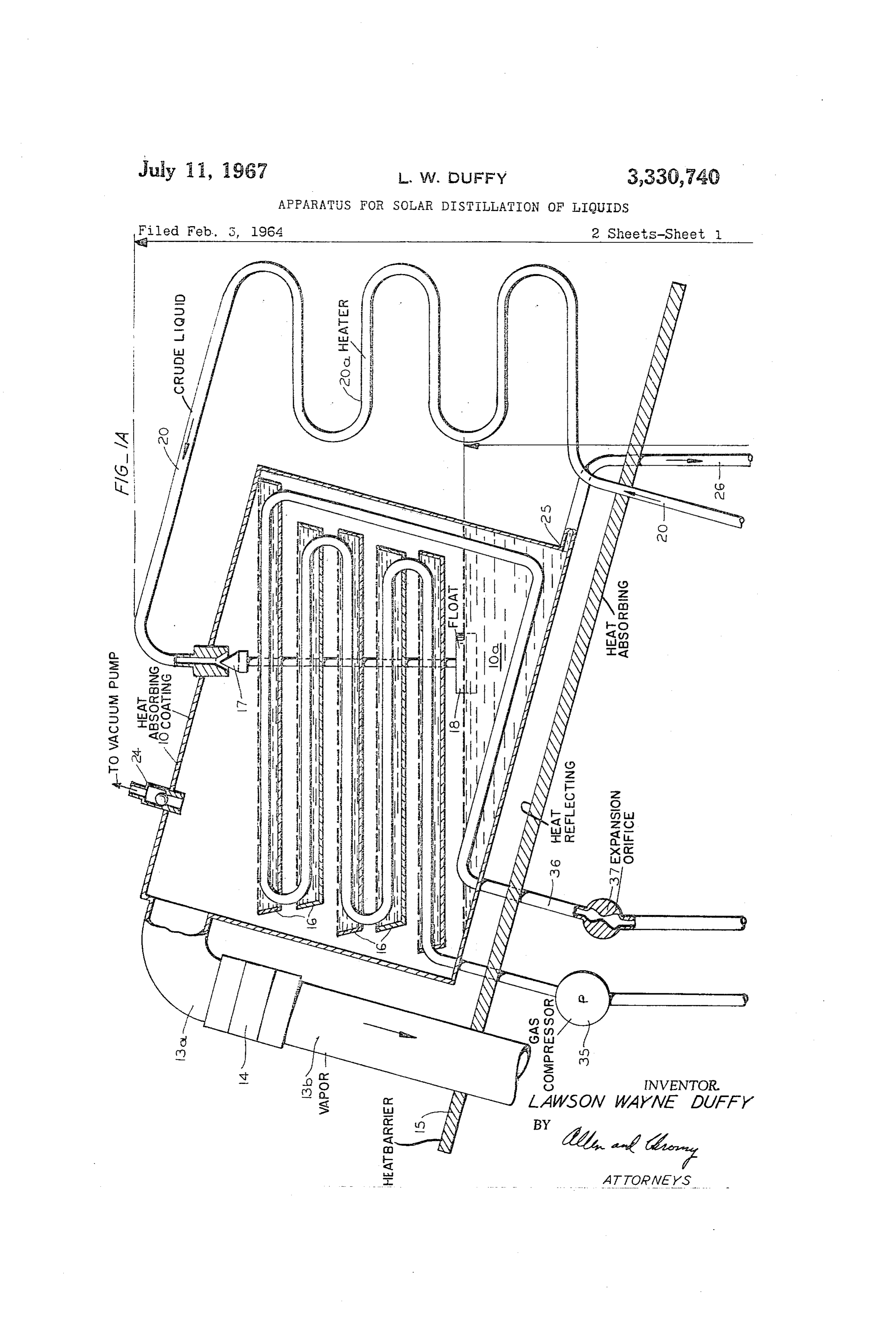
My invention pertains to apparatus and methods for the Furthermore, insulating material may be provided on the efficient and economical distillation of liquids with em O under side of the heat shield 15 to further reduce heat phasis on the demineralizing of sea water. An alternate passing therethrough to the condensing chamber 12. purpose of this invention is for the concentration or de The evaporator chamber 10 is preferably made of a hydration of fluids at relatively low temperatures by the cylindrical tubular cross section and is provided with a removal of the water therefrom. plurality of trays 16 which are supported level therein Although there are many highly efficient distillation 5 one above the other. The liquid inlet to the evaporating methods of public knowledge, most if not all of these chamber 10 is controlled by a valve 17 which is operated methods are not economically practical due either to by the float 18. This inlet is connected by the pipe 20 to limited volume, high initial cost, intermittent operation, the crude liquid reservoir 19 that is positioned on or below high maintenance and replacement costs, prohibitive space the surface of the earth. An evacuation check valve 24 is requirements, or a combination of these factors. These 20 provided to the top of evaporation chamber 10, and this factors have been considered in the development of my check valve outlet may be connected to the inlet of an invention in order to provide an apparatus that is efficient evacuating pump (not shown).
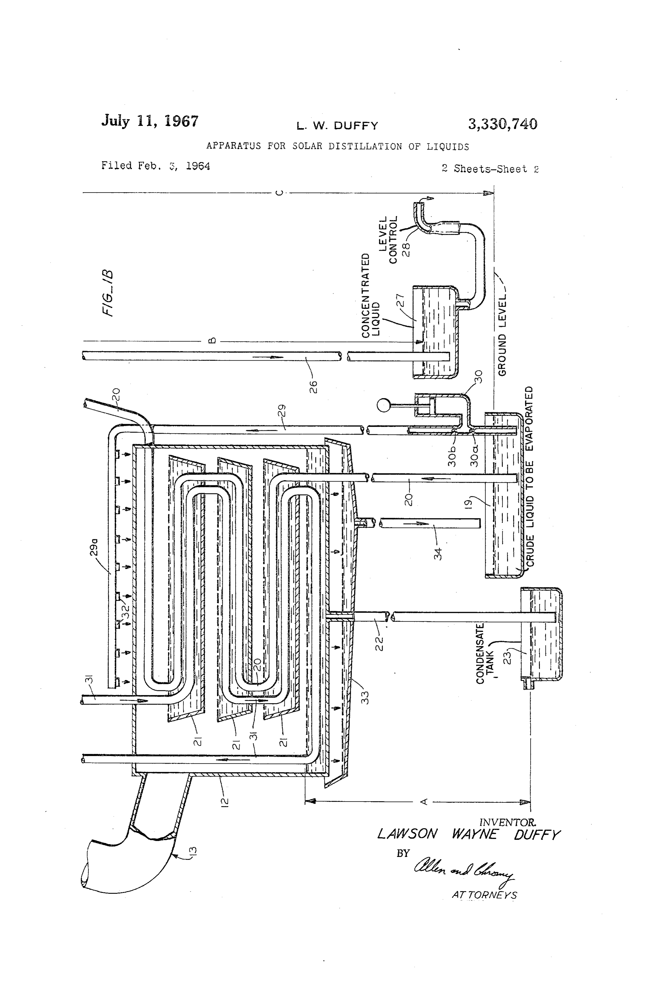
consistent with true economy. The condenser unit comprises a cylindrical chamber It is well established that water and most other liquids 12 that is similar to the boiler chamber 10 and a plurality will boil or vaporize at any temperature above their freez 25 of level trays 21 is provided therein to increase the con ing or solidifying point, providing that the pressure upon densing surface area. The pipe 20 through which crude the liquid is such as to permit molecules of the liquid to liquid is supplied to the evaporating chamber 10 also readily expand to the gaseous state. This principle is em passes through the condensing chamber 12 and sections of ployed through the use of barometric feed and outfall this pipe are positioned in the trays 21 so that heat is lines to induce and maintain a static low pressure within 30 transferred to these pipe sections from the water or other the evaporator and condenser portions of this apparatus. liquid accumulated in these trays and, as a result, the inlet The pre-heater section of this apparatus is normally liquid fed to the evaporating chamber 10 is preheated. intended to be heated by solar energy, preferably from The inlet liquid may also be additionally preheated by a large mass of heat absorbing material. Due to the rela passing it through the preheater field 20a which is posi tively low temperature requirement, low yield or semi 35 tioned above the heat barrier and reflector shield 15. expended atomic reactors may be employed as a source The heavier residual liquid which, in the case of ocean of energy for the pre-heater section. Other more conven water, is distilled in the evaporation chamber 10, will con tional fuels may be used to augment the above sources. tain the various salts and minerals dissolved in the ocean It is therefore an object of this invention to provide an water and is collected in the lower part 10a of the evapo improved distillation apparatus and method in which 40 rating chamber 10. This lower part of chamber 10 is pro there is provided an evaporator chamber supported at an vided with an outlet 25 which is connected to the pipe 26 altitude to which crude liquid is elevated by atmospheric and the outlet end of this pipe is positioned in the reservoir pressure as said liquid is required; said chamber is heated 27. This reservoir is provided with an outlet pipe which is by solar energy, and the vapor therefrom is supplied to a connected to the bottom thereof. The outfall 28 of this condenser chamber in which the product liquid is con 45 pipe is adjustable in height with reference to the reservoir densed and from which the accumulating product liquid 27 so that the level of liquid in the reservoir is maintained is dropped against atmospheric pressure to the product at a certain level, determined by the elevation of the liquid reservoir. Furthermore, a heat pump system is pro outfall.
vided between the boiler chamber and the condenser The condenser chamber 12 is cooled by water supplied chamber so that this distillation apparatus continues to 50 from the crude liquid reservoir 19. The cooling liquid is function during the night on a twenty-four hour basis. sprayed over the top of chamber 12 from a plurality of Other and further objects of this invention will be ap outlet jets 32 provided to the manifold 29a. This manifold parent to those skilled in the art to which it relates from is connected to the pipe 29 and pump 30 which is operated the following specification, claims and drawing.
Referring to the drawing briefly: 55 by a motor (not shown) and is provided with convention all inlet and outlet valves 30a and 30b, respectively, so
FIG. 1a is a view partially section of the part of this that liquid drawn into this pump from the reservoir 19 apparatus including the evaporation chamber; and through inlet check valve 30a is forced up through outlet FIG. 1b is a view partially in section of the part of this check valve 30b and pipe 29 to the manifold 29a. The apparatus including the condensing chamber and the vari cooling liquid sprayed over the condensing chamber 12 ous pipes broken off at the top of this view are intended 60 that flows down on the sides of this chamber drops to the to be continuations of similar pipes shown broken off at collector sump 33 and from this sump drains through the the bottom of FIG. 1 a. pipe 34 which is connected to the bottom of a sump. This Referring to the drawing in detail, reference numeral 10 liquid is collected in reservoir 19 and also serves to heat designates a tilted reactor or boiler chamber which is the liquid in this reservoir.
tilted so as to provide a sump portion 10a in the lower 65 Chambers 10 and 12 are at elevations of approximately part thereof. Chamber 10 is connected to the condenser barometric pressure altitude for the fluids to be distilled. chamber 12 by the relatively large connecting duct 13. Based on data given in Handbook of Chemistry and This connecting duct is of circular cross section and is Physics, this elevation for pure water is approximately made in two sections 13a and 13b connected by an in 33.83 feet at sea level; however, for sea water this eleva sulating sleeve 14 to limit heat conductively from the duct tion is somewhat less-that is, 33.07 feet and depends section 13a to section 13b. A reflector heat shield 15 is upon the salt and mineral content of the water. In order
Page 4
for the chambers 10 and 12 to be positioned so that the lecting sump 33 to the crude water reservoir 19. The evap heights A and B are approximately the same, these cham oration cooling system pump 30 can be electrically con bers may be positioned more or less side by side and suit trolled by conventional means to provide operation when able insulating material may be placed around chamber required to maintain temperature differential. 12 to insulate it from solar heat. The height C is such that Although the basic concept as described above operates crude liquid is readily Syphoned through the pipe 20 into economically, it is limited to hours of direct sunlight. By the top of chamber 10 through the valve 17 when this adding the heat pump system, including the pump 35, valve is opened. pipes 36 in the trays 16 of chamber 10, throttle valve 37 The operation of this device is as follows: and pipes 31 in the trays 21 of the condenser chamber, The heights A and B are assumed to be atmospheric O the system will operate continuously with very slight addi tional energy. In this system an aerosol is compressed by pressure altitude for the fluids to be distilled, and height C the pump unit 35 and the heat of compression is given to be syphoning elevation. The boiler 10, condenser 12 and connecting tube 13 are first evacuated by filling them throughthetubes up to liquid in the trays 16 within the boiler chamber 36. The aerosol expands after passing with fluids from reservoir 19 so that all air therein is ex pelled through evacuation check valve 24. A suitable pump 15 through the throttle valve 37 and absorbs its latent heat of vaporization from the liquid in the trays 21 in the (not shown) may be attached to pipe line 20 for pump condenser chamber 12. This heat is cycled through the ing liquid into chambers 10 and 12. When all air has been heat pump and, in turn, transferred to the boiler unit. This expelled, from the chambers, the system is vented to at heat pump unit can be electrically controlled by a conven mospheric pressure at reservoirs 19, 23 and 27; thus at tional thermostatically controlled circuit to provide auto
mospheric pressure will hold fluids at elevation levels A, matic operation
B, and C, since the open bottom ends of pipes 20, 22 and ential between boiler at any time when the temperature differ 25 are positioned in the reservoirs 19, 23 and 27 respec comes less than the desirable chamber and condenser chamber be tively. Alternatively, the required low pressure may be suitable thermostats positionedspread, which is detected by in the boiler chamber and produced in the chambers 10 and 12 by an aspirator or 25 by controlling said circuit with this thermostat. vacuum pump (not shown) attached to evacuation check While I have shown a preferred embodiment of the in valve 24.
With the system thus primed and the liquid tempera vention, it will be understood that the invention is capable of variation and modification from the form shown so that tures in all parts of the system equal, the vapor pressures its scope should be limited only by the scope of the claims above the liquids will also be equal and no reaction will 30 appended hereto.
take place. As the liquid temperature in the boiler cham What I claim is:
ber 10 increases above that of the condenser chamber 12, 1. Apparatus for continuously distilling crude liquid due to the heat-absorbing coating on the outer surface thereof, and also due to the effect of the reflector heat the surface anofevaporation comprising chamber at an elevation above shield, the liquid will boil until the vapor pressure above 35 raised thereto the earth such that crude liquid will be by atmospheric pressure, a condensing the liquid and its temperature are compatible. Since the chamber, means connecting said condensing chamber liquid and its compatible vapor pressure in the condenser to said evaporation chamber for transferring vapor chamber 12 are lower than in the boiler chamber 10, the saturated vapor will flow from the boiler chamber to the from the evaporating chamber to the condensing cham ber, means expelling the air from said chambers, a condenser chamber and condense on the interior Surfaces thereof and trays 21. The greater the temperature differen pipe connection between said evaporation chamber and a supply reservoir of crude liquid located on the surface of tial between the boiler chamber and the condenser cham ber, the greater the flash vaporization will be in the boiler the earth, said pipe connection having a valve inside of chamber, and such condition will continue at any tempera in saidevaporation said chamber, means actuated by the liquid ture down to the freezing point of the fluid concerned. 45 sive to evaporation chamber controling said valve respon the level of crude liquid in said evaporation cham
As the liquid in the sump 10a of the boiler chamber ber to admit crude liquid upon a fall in level, and vice vaporizes, the density of the residual fluid will increase to versa, said evaporation chamber having a heat-absorbing such an extent that its weight is great enough to cause it coating whereby said chamber is heated at least part of to drain down against atmospheric pressure to effluent the time with solar energy absorbed reservoir 27. As the fluid level in sump 10a lowers, the connection between the bottom partinofsaidsaidcoating, a pipe evaporation
float 18 opens valve 17 and allows crude liquid to be chamber and a tank for residual liquid located on the syphoned from the crude fluid reservoir 19 through the surface of the earth so that the residual liquid drops to heat exchange tubes 20 immersed in the liquid in trays 21 in the condenser chamber 12. Since the input liquid is nor said2. tank when it is concentrated through said evaporation. Apparatus for continuously distilling crude liquid mally at a lower temperature than the product liquid in 55 comprising an evaporation chamber at an elevation above the condenser trays 21, much of the latent heat of vapor ization which was given up in the condensation of the the surface of the earth such that crude liquid will be product liquid will be absorbed by the liquid in the heat raised thereto by atmospheric pressure, a condensing exchange tubes 20. Additional heat will be absorbed from chanmber, means comprising a pipe connecting said con densing chamber to said evaporation chamber for trans the preheater field 20a and the input liquid enters the 60 ferring vapor from the evaporating chamber to the con boiler chamber in a heated condition with respect to the vapor pressure within the system. The additional heat ab densing chamber, means expelling the air from said cham sorbed will be transferred to the condenser unit as latent bers, a pipe connecting said evaporation chamber and a heat of vaporization. Some of this heat must be dissipated Supply reservoir of crude liquid located on the surface of from the condenser unit to provide an adequate tempera the earth, said last mentioned pipe having a valve, means ture differential between condenser and boiler units. Some 65 controlling said valve responsive to the level of crude of the latent heat is dissipated from the condenser unit by liquid in said evaporation chamber to admit crude liquid natural air flow around that section. Heat dissipation is upon fall in liquid level therein, and vice-versa, said evapo further enhanced by an evaporization cooling system ration chamber and said condensing chamber each having wherein water is lifted by pump 30 through the pipe 29 a plurality of liquid holding trays therein, said last men to manifold 29a and is expelled through jets 32 to saturate 70 tioned pipe being adapted to feed crude liquid into said an absorbent mesh (not shown) covering the condenser trays in said evaporation chamber, a part of said last chamber 12. As the water is evaporated into the surround mentioned pipe being positioned in the trays in said con ing air, heat is absorbed from the condenser chamber 12. densing chamber for preheating the crude liquid fed to Excess water running off of the chamber into sump 33 also absorbs heat and carries residual minerals from the col- 75 said evaporation chamber, said evaporation chamber hav
Page 5
ing a heat-absorbing coating whereby said chamber is piping positioned in said trays 6 heated at least part of the time with solar energy absorbed in both of said chambers, in said coating, and means comprising another pipe be a heat pump connected to said pipe system and a throttle tween the bottom part of said evaporation chamber and a device, said heat pump pumping gas out of the pipe sys tank for residual liquid located on the surface of the earth tem in said condensing chamber and compressing it into so that the residual liquid drops to said tank when it is said pipe system positioned in the trays of said evapo concentrated through said evaporation. ration chamber to heat liquid therein and said throttle 3. Apparatus for continuously distilling crude liquid pipe device allowing said compressed gas to expand into said comprising an evaporation chamber at an elevation above system positioned in said condensing chamber to absorb the surface of the earth such that crude liquid will be 0. the bottom heat therefrom, another pipe connection between raised thereto by atmospheric pressure, a condensing for residualpart of said evaporation chamber and a tank liquid located on the surface of the earth chamber, means comprising a pipe connecting said con so that the residual liquid drops to said tank when it is densing chamber to said evaporation chamber for trans concentrated through said evaporation. ferring vapor from the evaporating chamber to the con 5. Apparatus for continuously distilling crude liquid densing chamber, means expelling the air from said comprising an evaporation chamber at an elevation above chambers, a pipe connection between said evaporation the surface of the earth such that crude liquid will be chamber and a supply reservoir of crude liquid located raised thereto by atmospheric pressure, a condensing on the surface of the earth, said pipe connection having chamber, means comprising a pipe connecting said con a valve, means controlling said valve responsive to the densing chamber to said evaporation chamber for trans level of crude liquid in said evaporation chamber to admit 20 ferring vapor from the evaporation chamber to the con crude liquid upon fall in liquid level therein, and vice densing chamber, means expelling the air from said versa, said evaporation chamber having a heat-absorbing coating whereby said chamber is heated at least part of chambers, a pipe connection between said evaporation chamber and a supply reservoir of crude liquid located the time with solar energy absorbed in said coating, a on the surface of the earth, said pipe connection having a heat shield for shielding said condensing chamber from 25 valve, means controlling said valve responsive to the level solar heat, said heat shield having heat-reflecting means of crude liquid in said evaporation chamber to admit for reflecting solar heat to said evaporation chamber, an crude liquid upon fall in level therein, and vice-versa, other pipe connection between the bottom part of said said evaporation chamber having a heat-absorbing coating evaporation chamber and a tank for residual liquid located whereby on the surface of the earth so that the residual liquid drops 30 with solarsaidenergy chamber is heated at least part of the time absorbed in said coating, a manifold to said tank when it is concentrated through said evapo having a plurality of jets positioned so that liquid pumped ration.
4. Apparatus for continuously distilling crude liquid into said manifold is sprayed over said condensing cham ber, and a collecting sump positioned under said con comprising an evaporation chamber at an elevation above densing chamber collecting the preheated liquid running the surface of the earth such that crude liquid will be 35 off raised thereto by atmospheric pressure, a condensing saidofsump said condensing chamber and a drain connected to draining said Sump to said crude liquid reser chamber, means comprising a pipe connecting said con voir, another pipe connection between the bottom part of densing chamber to said evaporation chamber for trans ferring vapor from the evaporating chamber to the con said evaporation chamber and a tank for residual liquid located on the surface of the earth so that the residual densing chamber, means expelling the air from said 40 liquid drops to said tank when it is concentrated through chambers, a pipe connection between said evaporation said evaporation.
chamber and a supply reservoir of crude liquid located References (Cited on the surface of the earth, said pipe connection having a UNITED STATES PATENTS valve, means controlling said valve responsive to the level of crude liquid in said evaporation chamber to admit 45 062?342?2 2/1944 Schenk ----------------------- 202-205 crude liquid upon fall in liquid level therein, and vice 2,490,659 12/1949 Snyder ------------- 202-205 versa, said evaporation chamber having a heat-absorbing 2,636,129 4/1953 Agnew -------------------- 159-1 ? coating whereby said chamber is heated at least part of 716,446?2 8/1955 ROSS ------------------------- 1-?159 the time with solar energy absorbed in said coating, said 2,777,514 1/1957 Eckstrom ---------- 159- 24 X evaporation chamber and said condensing chamber each 50 3,232,846 2/1966 Kimmerle ----------- 202-185 having a plurality of level liquid holding trays, said first mentioned pipe connection supplying crude liquid to the NORMANYUDKOFF, Primary Examiner, trays in said evaporation chamber, a pipe system having J. SOFER, Assistant Examiner,
Provenance
- Collection
- Cited prior art
- Original PDF
- patentimages.storage.googleapis.com →
- Filed
- 1964-02-03
- Pages
- 5
- Method
- pdftotext (the PDF's own text layer) + pdftoppm 300dpi page scans
- Source
- Google Patents bibliographic record
- Granted
- 1967-07-11
- Inventors
- Duffy Lawson Wayne
- Transcribed from
- patentimages.storage.googleapis.com →