patent · US3317406
Hot air desalinization apparatus
2 May 1967
Page 1
Drawing sheet — no readable text.
Page 2
United States Patent Office 3,317,406 Patented May 2, 1967
3,317,466 It is another object of this invention to provide for a HOT AIR DESALNZATION APPARATUS System of converting saline fluid which may be compact and potable.
Kim D. Beard, 1040 S. Magnolia,
Los Angeles, Calif. 90006 It is also an object of this invention to provide for a Filed May 1, 1963, Ser. No. 277,372 System of converting saline fluid which may comprise a 6 Claims. (C. 202-180) large structural installation.
This invention relates to the conversion of a saline fluid It is a further object of this invention to vaporize the to a potable state. saline fluid in order to purify it.
For the survival of man one of the most necessary It is another object of this invention to condense the staples besides food in the availability and use of Water. O vaporized
saline fluid to recover a purified fluid.
also an object of this invention to convey and
Throughout the world there are numerous areas which store the purified fluid for use as desired. are considered to be waste land since there is no supply It is a further object of this invention to utilize a heat of water available which is pure enough to be used either eXchange relationship between the saline fluid and the for drinking purposes or to be used for irrigation and the 15 vaporized converted fluid.
growing of food or the like. If there is a source of water It is another object of this invention to utilize the available, it generally is of such an impure state or has initial heat of the purified fluid to assist in converting the such a high content of salt that it can not be used for any saline fluid.
purpose at all. In the past, there have been many at It is also an object of this invention to provide for the tempts devised to convert this water to a useful purpose 20 recirculation of any unvaporized saline fluid back into by purifying it or removing or reducing its salt content. the system to convert it.
Generally, these methods employed a very complicated arrangement of heating systems, such as steam or electrical tem of trays to assist inofconverting It is a further object this invention to utilize a sys the saline fluid to a heat, to raise the temperature of the water so that it would become vaporized and then subsequently passed through 25 potable state.
It is toanother object of this invention to utilize solar a complicated arrangement to cool and condense the vapor energy assist in vaporizing the saline fluid. laden air to remove the condensate which would then Other objects and various further features of the in be water suitable for drinking and irrigation purposes.
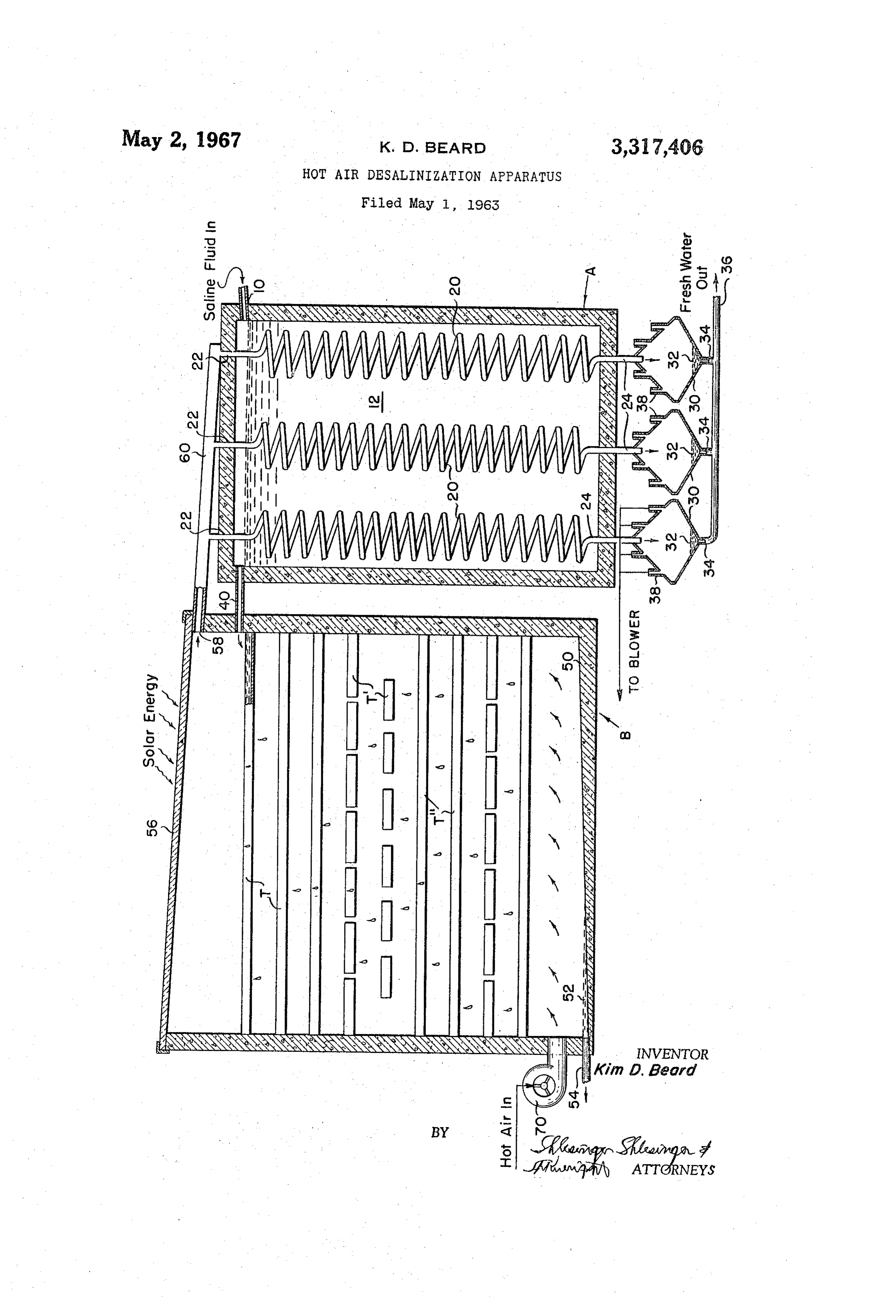
Systems and structures have also been devised which were vention will be pointed out or will occur to those skilled in the art from the following specification when taken of a more compact nature by eliminating the use of a 30 into complicated heating system and substituting a system of which:conjunction with the accompanying drawing in mirrors to utilize solar energy to raise the temperature of the water to a vapor state with subsequent cooling to hotThe air drawing discloses a side view of a system for the conversion of saline fluid into a potable state.
obtain purified water. However, an arrangement used to The system for converting saline fluid to a potable employ mirrors to good advantage was generally quite 35 State consists of a unit made up of two parts A and B. complicated or the output of the system was so small The basic unit may be of any size ranging from a com that it was not economically feasible to advantageously pact portable unit to a multi-storied structural installa employ the system. Systems which depended primarily tion.
upon solar energy to convert fluid were deficient in that used toThe drawing discloses a multi-storied structure convert a substantial amount of saline fluid to a they did not remove a satisfactory amount of the salt or 40 potable state by means of a hot air process. Each of the the like during the first passage of the fluid through the units, condenser apparatus, necessitating additional runs of the now di of concrete, metalAand and evaporator B may be constructed luted fluid which was time consuming. Further, this sys should be desired it is even within plastic as desired. Also, if it the scope of this invention tem could not be used in any area where there would be to arrange more than two parts in a systematic order to any sort of demand due to its meager supply and the convert amount of time needed to furnish that supply. Also, this example the saline fluid to a potable state. By way of system could not be readily employed within a cold re principlesonly two parts are illustrated as embodying the gion or climate. Therefore, the systems employed in the and B is air tightpresent of the system. Each of the units A past to convert saline water to a usable state have gen which is resistant to the corrosion with and provided a suitable lining of the saline fluid or erally been so complicated and bulky that their output 50 the like.
does not justify the expense of converting the water or if a more compact and simplified system is used, the Supply inlet 10first
The tank or condenser unit A is provided with an for the saline fluid 12 which is contained within of water either cannot meet the demand or the "con the condenser unit. The temperature of the saline fluid verted' water still has such a high saline content that it is not satisfactory and must be rerun through the System. 55 as it enters the condenser unit is the natural temperature of the body of water from which it has been taken.
It is therefore an object of this invention to convert With ocean or sea water this temperature generally is saline fluid to a potable state. around 50 degrees F. Also provided within the condenser It is another object of this invention to convert the unit A are a plurality of vapor condensing heat exchangers saline fluid to a potable state in an economical and ex shown as condensing coils 20 positioned within the body peditious manner. of the Saline fluid contained within the condenser unit. It is also an object of this invention to provide for 60 These condensing coils 20 have generally a spiral like the conversion of a substantial amount of saline fluid to configuration as shown, but it is contemplated that any a potable state to satisfy the demands of the area.
It is a further object of this invention to convert saline form may be used which would perform the function of a condensing coil. Further, these coils can be constructed fluid into a potable state by utilizing the natural resources 65 of any suitable heat exchange material such as glass, of the area.
It is another object of this invention to utilize air to willplastic or any material which will not corrode easily, yet vaporize the saline fluid. conduct heat rapidly. Vapor laden moist hot air enters the coils 20 through the inlets 22 and flows down
It is also an object of this invention to employ a hot through air system to vaporize and convert the saline fluid. the coils positioned within the saline fluid in a It is a further object of this invention to provide basic 70 heat eXchange relationship such that the moisture laden air is condensed.
ally a two part unit to convert saline fluid to a potable. The purified fluid exits through the coils at 24 to a
Page 3
chamber or vessel 30 provided adjacent the outlet 24 of 70. the inclined bottom 59 in evaporator B is a fan or blower The fan or blower uses the hot air either from the the condensing coil. These distilled water collecting ves surrounding region, as in a desert, or preheated air by Sels may be formed in a conical configuration or any desired shape since the purpose of the structure is to any suitable means when necessary, as in a temperate or cold climate. This hot air is blown into evaporator B at receive the condensed fluid which is now of a substan the base thereof such that it flows upwardly, around and tially pure state or condition so that it may be used as desired for drinking or irrigation. Further, the distilled through the sections of trays. Although only one blower is shown it is within the scope of this invention that fluid collecting retorts are generally positioned adjacent numerous blowers would be employed dependent upon the condenser unit A but may be placed below it such the efficiency of the system. This hot air is of such a that the ground could assist in cooling the fluid. The O high temperature that it will contact and vaporize the potable water 32 is withdrawn from the condensate cham saline fluid entering through conduit 40 and flowing among ber 30 through the outlets 34 and the conduit 36 to a the tray sections to carry it off through the outlet 58 and distribution system common within the art. The retorts or vessel are further provided with a plurality of air into the system of condensing coils. Arranging the vents 38 to remove any of the hot air which has accu fluid insystem blower adjacent the outlets 54 for the unvaporized evaporator B, and in combination with a valve mulated in the vessels 30. If desired, this hot air could be recirculated back to the system such that it may be system in order if used, assists in vaporizing portions of that fluid to purify it.
used to assist in the vaporization of the saline fluid as it OPERATION is being converted into a purified state.
There is provided within the condenser unit A an outlet 20 In summation, cool saline fluid flows into the condenser 40 for the saline fluid, the temperature of which has been unit A wherein there are arranged condensing coils in somewhat raised due to the heat exchange relationship heat exchange relationship with the fluid, which coils between the coils 20 and the fluid contained within the are used to condense the vaporized fluid in order to purify tank A. The saline fluid flows out of the condenser A it. The condensed fluid is accumulated within a series through the conduit 40 into the evaporator unit B. Posi 25 of fluid collecting vessels from which it is subsequently tioned within the evaporator B are a plurality of numer dispensed as desired. The saline fluid flows into evapo ous and closely juxta-positioned trays T, T, T' supported rator unit B where the tray arrangement is used to vapor and held in place by any suitable means. These trays ize the fluid. A fan or blower is used to introduce either may be constructed of any material which will not be the hot air of the surrounding region or preheated air corroded easily by contact with the saline fluid, such as 30 to collect and absorb water vapor as the air rises within glass, piastic, wood, compressed cardboard, etc. The evaporator B and among the tray sections. The moisture manner of distributing the saline fluid from condenser A laden vaporized air is then distributed to the condensing to the trays T, T, T' through the conduit 40, may be coils of condenser unit A to purify and collect the fluid. by any means. For example, there could be a conduit The unvaporized fluid in evaporator B is recirculated to provided for each row of uppermost trays T. Further, 35 the trays of evaporator unit B. - it is contemplated that there might be only one conduit While the invention has been described in connection which would distribute the fluid through a centrally lo with different embodiments thereof, it will be understood cated system to the upper most bank of trays T. The that it is capable of further modification, and this applica trays are rather shallow and of such a depth that fluid 40 tion is intended to cover any variations, uses, or adapta will flow over the sides of the trays and pass down by tions of the invention following, in general the principles gravity through the receptacle B and the other trays T', of the invention and including such departures from the T' further provided therein. As shown there are a plu present disclosure as come within knowing or customary rality of trays T which are arranged side by side in a practice in the art to which the invention pertains and stacked relationship. Further, the disposition of one row as may be applied to the essential features here and before or section of trays T is designed to be angularly displaced 45 set forth and fall within the scope of the invention or the with respect to the disposition of another section or row appended claims.
of trays T, T' to provide for a continuous flow and Having thus described my invention what I claim is: vaporization of the fluid as it passes through the evapora 1. Apparatus for obtaining a distillate comprising: tor B. As shown, the section of trays T is disposed in (a) an evaporative unit having a plurality of vertically a relationship different from that of section T. The 50 spaced rows of evaporative trays which receive and sections and rows of trays are alternately disposed hold saline water to be distilled; throughout the tank B. (b) a saline water inlet at the top of said evaporative Any saline fluid which has not been vaporized, flows unit immediately above the top row of trays which to the inclined bottom 50 of the evaporator B such that supplies saline water to said trays so that it fills the saline fluid 52 accumulates at one section. An out with excess water falling successively from the top let 54 recirculates the fluid back into the system at evapo to the lower most row of trays; rator B. If desired, a float operated or similar valve (c) an excess saline water outlet at the bottom of said arrangement may be employed to dispense the accumu evaporative unit to pass out excess saline water; lated fluid at various desired intervals. (d) a top panel above said top row of trays through At the upper most portion of the evaporator B is an 60 which sunlight is passed;
inclined cover or top 56 made of glass or the like such (e) a connecting dry air supply passage which has an that the rays of the sun will strike the fluid contained open end immediately below the lowermost row of within the trays T to assist in the vaporization of the trays for passing hot air into said evaporative unit fluid while converting it to a substantially pure condi and up around said rows of trays; tion. If desired a mirror arrangement in combination (f) a forced air unit connected to the other end of with the solar rays could be utilized. The inclined nature said dry air supply passage; of the roof enables any of the vaporized droplets to flow (g) a warm moist air outlet immediately below said toward the outlet 58 which is provided within the upper top panel and above said top row of trays through most area of the evaporator B. The outlet 58 is for which moisture-laden air passes; - vaporized air which flows into the system 60. The sys 70 (h)contains a condenser unit beside said evaporative unit which a body of saline water and has a liquid tem. 60 distributes the moisture laden vaporized air to level over flow conduit at the side adjacent said the inlet 22 of the condensing coils 20 where it is sub evaporative unit for carrying saline water from the sequently condensed and a purified fluid removed a upper end of said condenser unit to said saline water
Generally disposed adjacent the lower most portion of 75 inlet;
Page 4
(i) a condenser unit saline water inlet above the water 4. Apparatus for obtaining a distillate as set forth in level in the condenser unit for supplying saline water claim 1, wherein:
to said condenser unit by gravity feed; (a) means are provided for returning air from the col (j) a plurality of vapor condensing heat exchangers lecting chamber to the evaporative unit. immersed in the body of water in said condenser unit 5. Apparatus for obtaining a distillate as set forth in and connected to said warm moist air outlet of said claim 1, wherein:
evaporative unit adjacent the tops thereof; (a) said vapor condensing heat exchangers are con (k) each of said vapor condensing heat exchangers denser coils disposed vertically in said condenser unit. being connected to a collecting chamber at the lower 6. Apparatus for obtaining a distillate as set forth in end thereof for collecting fresh distilled water; claim 1, wherein.
(l) the warm moist air passing downward through the (a) said evaporate unit, and said condenser unit, are said vapor condensing heat exchangers from top to large building structures. bottom thereof, heating the adjacent water so that the water is warmed thereby rising to the liquid level References Cited by the Examiner over flow outlet, while the cooler water entering the UNITED STATES PATENTS condenser unit through said saline water inlet tends to sink to the bottom of the condenser unit; and 102,633 5/1870 Wheeler -------- 202-234 X (m) said chambers being vented to allow the cool air 430,215 6/1890 Maxim ----------- 203-49 X from the vapor condensing heat exchangers to pass 450,361 4/1891 Baird ----------- 202-180 X freely through said chamber with no back pressure. 20 2,372,846 8/1942 Nettel ----------- 202-236 X 2. The apparatus for obtaining a distillate as set forth 3,210,260 10/1965 Denker ------------ 202-236 in claim 1, wherein: FOREIGN PATENTS (a) successive rows of trays in the evaporative unit are 454,558 9/1936 Great Britain. disposed in different directions.
3. Apparatus for obtaining a distillate as set forth in 25 NORMANYUDKOFF, Primary Examiner. claim 1, wherein:
(a) said air passed through the blower to the evapora J. B. DONIHEE, D. EDWARDS, Assistant Examiners. tive unit is preheated,
Provenance
- Collection
- Cited prior art
- Original PDF
- patentimages.storage.googleapis.com →
- Filed
- 1963-05-01
- Pages
- 4
- Method
- pdftotext (the PDF's own text layer) + pdftoppm 300dpi page scans
- Source
- Google Patents bibliographic record
- Granted
- 1967-05-02
- Inventors
- Kim D Beard
- Transcribed from
- patentimages.storage.googleapis.com →