patent · US3965683
Solar electrical generating system
29 June 1976
Page 1 — bibliographic record
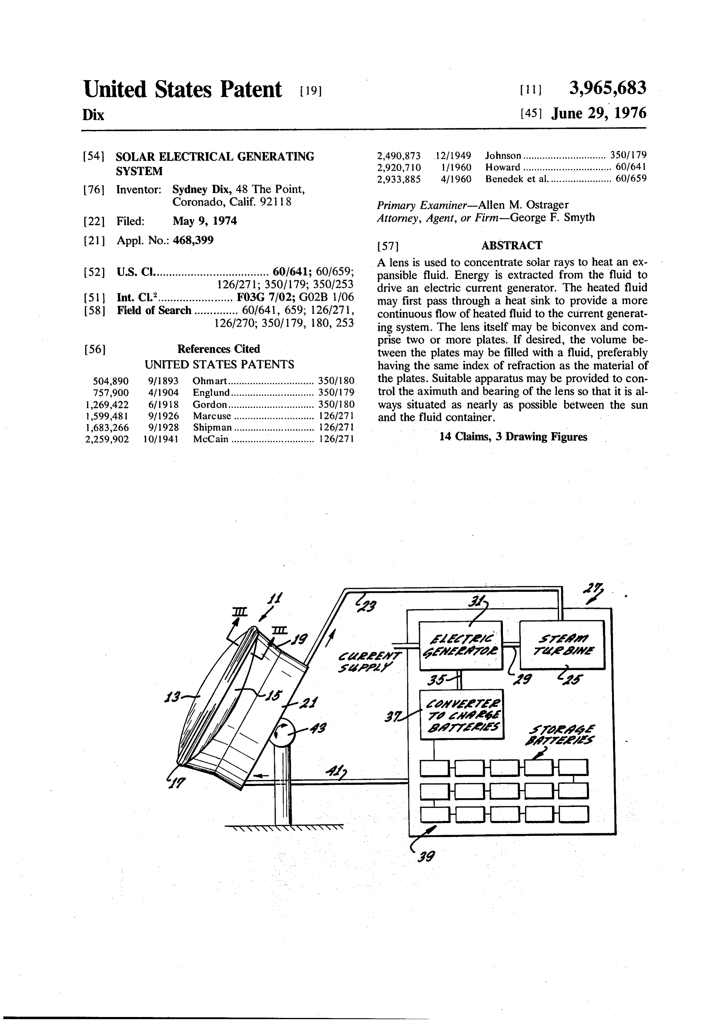
United States Patent (19) 11) 3,965,683 Dix (45) June 29, 1976 54 SOLAR ELECTRICAL GENERATING 2,490,873 - 12/1949 Johnson.............................. 350, 79 SYSTEM 2,920,710 1/1960 Howard................................ 60/64 2,933,885 4/1960 Benedek et al....................... 60/659 76 Inventor: Sydney Dix, 48 The Point,
Coronado, Calif. 921 18 Primary Examiner-Allen M. Ostrager 22 Filed: May 9, 1974 Attorney, Agent, or Firm--George F. Smyth (21) Appl. No.: 468,399 57 ABSTRACT A lens is used to concentrate solar rays to heat an ex (52) U.S. Cl..................................... 60/641; 60/659; pansible fluid. Energy is extracted from the fluid to 2 126/271; 350/179; 350/253 drive an electric current generator. The heated fluid 51 Int, C.'........................ F03G 7/02; G02B 1106 may first pass through a heat sink to provide a Oe 58) Field of Search.............. 96.5: 22 continuous flow of heated fluid to the current generat 126/270; 350/179, 180, 253 ing system. The lens itself may be biconvex and com prise two or more plates. If desired, the volume be 56) References Cited tween the plates may be filled with a fluid, preferably UNITED STATES PATENTS having the same index of refraction as the material of 504,890 91893 Ohmart............................... 350/180 the plates. Suitable apparatus may be provided to con 757,900 4/1904 Englund..... ... 3501179 trol the aximuth and bearing of the lens so that it is al 1,269,422 6/1918 Gordon...... ... 350/180 ways situated as nearly as possible between the sun 1,599,481 9/1926 Marcuse.... ... 126/271 and the fluid container.
1,683,266 9/1928 Shipman.... ... 126/27 2,259,902 10/1941 McCain.............................. 126/271 14 Claims, 3 Drawing Figures
12 124/26/26
Aas
Page 2
Drawing sheet — no readable text.
Page 3
for expansion and contraction of the lens as it is heated
SOLAR ELECTRICAL GENERATING SYSTEM by the sun and cooled at night. In other words, it may
BACKGROUND OF THE INVENTION
serve as an expansion joint. Further, if desired, the pressure of the fluid within the lens, and its chemical
The recent energy crisis has clearly illustrated the 5 composition, may also be controlled and altered. need for additional sources of energy if a desirable In one embodiment of the invention, the Solar rays standard of living is to be maintained. It is well known may be concentrated onto a boiler which heats a fluid, that the use of petroleum products to heat and light such as water, until it becomes steam. The steam may homes, to drive automobiles, etc., can be continued be passed through a turbine which drives a generator. only for a finite period of time before the supply of 10 In an alternate embodiment of the invention, the those products is completely exhausted. Consequently, fluid heated by the solar rays may be either liquid or a great number of projects have been undertaken to gas. After it is heated, it may be passed through an develop additional or alternate sources of power. eutectic material which will serve as a latent heat stor It is also well known that the use of petroleum-based age unit or heat sink. The heat in the fluid will melt the products to fulfill energy needs is not only wasteful of 5 metal and raise its temperature until it is substantially those products but also detrimental to ecological con equal to that of the heated fluid as it passes through the siderations due to smog and other pollution their use eutectic. The fluid may then continue on to a current creates. Thus, not only is it necessary and desirable to generation device which it can drive either through produce and utilize other sources of energy, but it is expansion or merely as a result of fluid flow. also necessary that those additional energy sources be When the sun's rays provide less heat to the fluid as inexpensive and as pollution free as possible. a result of its position relative to the surface of the In many cases, large energy producers such as utility earth, the latent heat stored in the eutectic may be companies have been turning to nuclear power. While transferred back to the fluid, and, depending upon the this alternative may be satisfactory in the case of pro 25 quantity of the eutectic, can be used to drive the gener duction of massive quantities of electricity, it is pres ator for several hours after the sun has set. ently unsuitable for small applications due to the fact In either case, or in any other embodiment of the that such power plants are very expensive and, at a invention, the current generating device can be con minimum, waste a great deal of heat. nected to an electrical circuit so that any excess current When attempting to provide an alternative power 30 which it is generating can be stored in a bank of storage source for much smaller applications, such as a single batteries or other power cells until needed. building or home, an automobile, etc., there have been Thus, the present invention comprises a relatively no satisfactory developments which are sufficiently simple device which can be produced in any desirable reliable, low cost, and low pollution output. size so as to provide heating, cooling, and electrical In many instances, developers of such systems have 35 power to a home, a large building, or even to a vehicle. attempted to accomplish the desired results by captur Although the invention will be illustrated with respect ing and utilizing solar energy, but the systems designed to different embodiments, those skilled in the art, upon have been expensive, complex, and often unsuitable for review of the following detailed description and the small applications. For example, most of the systems drawings, will quickly become aware of the fact that designed thus far require the use of large Solar panels there are innumerable embodiments in which the in which must be spread out in a field or on a rooftop. 40 vention may be employed, many of which will become They often require that the building with which they immediately apparent. In any event, it should be real are to be used be constructed specifically so as to uti ized that the scope of the invention is not limited to the lize the system. described embodiments, but to whatever may be fairly To date, no relatively small, unobstrusive, inexpen 45 covered by the claims.
sive, and pollution free alternative for the generation of DESCRIPTION OF THE DRAWING power and heat has yet been devised.
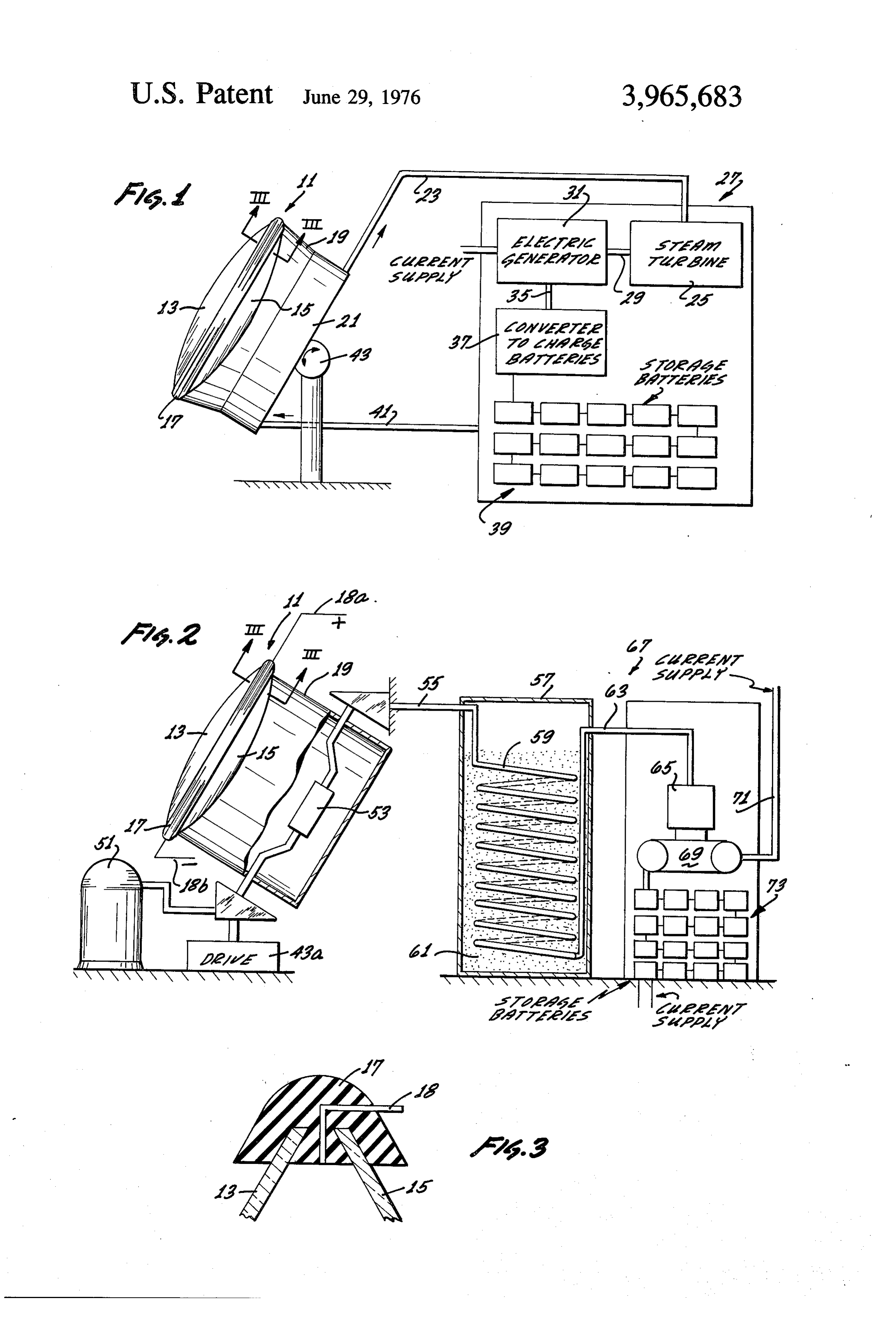
SUMMARY OF THE INVENTION FIG. 1 comprises a schematic illustration of a first embodiment of a solar generator apparatus employing
The present invention relates to a solar driven power the invention; n source which is completely pollution free, inexpensive, FIG. 2 comprises a schematic illustration of a second and very simple in its operation and maintenance. embodiment of structure which may employ the inven The invention proposed here utilizes a lens for the tion; and concentration of solar infra-red rays upon a container FIG. 3 comprises a partial sectional view of one em carrying a fluid which is to be heated by those rays. The 55 bodiment of a lens which may be employed with the heated fluid may then be directed to a power genera present invention, as seen along a line III-III in either tion or energy conversion apparatus which develops an FIG. 1 or FG, 2.
electrical current which may be delivered directly to DETAILED DESCRIPTION the using apparatus or to a bank of batteries or other power cells for storage until such time as the electrical 60 Referring now to the drawings in greater detail, and energy is needed. specifically to the lens structure shown in FIGS. 1-3, The lens may be biconvex; if desired, it may be there is illustrated an exemplary lens 11 which may formed by two or more inexpensively sag-formed circu comprise at least two plates or lens faces 13, 15. The lar glass plates, between which is confined a fluid hav plates may be formed in any suitable manner and of any ing substantially the same index of refraction as the suitable material. However, as presently envisioned, it plates. Also, if desired, a flexible extrusion or other 65 might be preferable to form the plates from flat sheets type of device may encircle the periphery of the plates of glass which are heated and then allowed to sag into and be provided with structure so that the plates may a mold of suitable configuration. In any event, it will be captured therein; this element may be used to allow often be preferred that the lens plates be of circular
Page 4
configuration and the lens be biconvex so as to provide generator can generate and no current will be transmit the most efficient transmission and concentration of ted to the converter 37. When the power demand is solar waves which pass through the lens. lower, the excess current generated can be delivered to As shown particulary in FIG. 3, a flexible element or the battery charger'37, and into the batteries 39. expansion-joint member 17 may be formed, for exam- 5 On the other hand, when the power demand is ple, as an extrusion, and utilized to join the plates 13 greater than that which can be supplied by the genera and 15 about the peripheries thereof and hold the tor, the battery potential may be used to supplement or plates in relationship to one another. If the element 17 replace it altogether. Also, when the Sun has set and no is provided so as to be of flexible material, heating and additional heating of the fluid in the boiler 21 is possi cooling of the lens as it undergoes daily solar cycles can 10 ble, the batteries 39 can be utilized for a period of time, be easily and rapidly absorbed in the expansion joint determined by their capacity and their number, to pro 17, thus preventing damage to the lens and allowing vide electrical power.
efficient operation thereof. As energy is extracted from the fluid, for example by In many cases, it will be desirable to improve the expansion of steam in the turbine 25, the steam may be efficiency of the lens by manufacturing it in such a way 15 condensed back into water and then returned, via a that it is either a solid piece of glass or, at least, substan pipeline or similar apparatus 41 to the boiler 21. tially simulates such a solid piece of glass. In an em It will often be desirable to insure that the lens 11 is bodiment which is usually less expensive than a solid situated directly between the sun and the boiler 21 at piece of glass, a liquid filler may be installed between all times. This will provide the most efficient use of the the plates 13 and 15. Preferably, the index of refraction 20 solar rays. To accomplish this, a drive apparatus 43, of the liquid filler should be equal to or about the same including a timer, a suitable light-actuated solenoid, or as that of the material of the lens plates so as to sub a similar apparatus, may be utilized to adjust the azi stantially eliminate reflection of solar waves as they muth and bearing of the gimbal 19 to properly locate pass through the various materials of the lens. the lens. Thus, it can be seen that the present invention Of course, it will be realized by those skilled in the art 25 may be employed in relatively simple apparatus of very that the lens could be manufactured utilizing more than low complexity, also, it may be adjusted in size in ac two plates and, in fact, a series of lenses could be pro cordance with the task to be accomplished. For exam vided to increase the efficiency of the device. Also, in ple, the device could be manufactured of such a size the abovedescribed embodiment, it would be possible, that it could be used to power either an automobile or if desirable, to install one or more ports 18 through the 30 a very large building. Similarly, a bank of lenses and expansion joint 17 so that fluids may be added to or heat exchangers may be provided to eliminate the re removed from the space between the plates in order, quirement for one large lens which may be too expen for example, to adjust the focal length or index of re SVe.
fraction of the lens. Similarly, if desired, a cathode and Referring now to the embodiment of FIG. 2, it will be anode 18a and 18b may be installed in the volume 35 realized by those skilled in the art that, if desired, water between the plates so as to allow selective electrical could be utilized to generate steam in the manner de current excitation of the lens filler in order to eliminate scribed with respect to FIG. 1. For the sake of illustra or generate various chemical elements in the filler to tion, however, it will be assumed that this embodiment alter the operation of the lens. - includes a source 51 of pressurized fluid such as air, In any event, it can be seen by those skilled in the art 40 water, etc., which may be passed through a heat ex that a lens which may be utilized in accordance with changer 53 at the rear of the gimbal housing 19, the present invention may be provided with as simple wherein it is heated by the solar rays passing through or as complex structure as may be desired for the appli the lens 11.
cation involved. Although the gimbal housing 19 may be mounted in With respect now to FIG. 1, it can be seen that the 45 any suitable manner, there has been illustrated a drive lens 11 may be situated in a gimbal housing 19, at the apparatus 43a which may be utilized so as to maintain rear of which may be located a boiler or other heat the most efficient location of the lens 11 relative to the exchanger 21. Thus, the solar rays passing through the sun. In any event, as the heated air or other fluid, lens can be directed onto the boiler 21 in order to heat whether gas or liquid, passes from the heat exchanger a fluid, such as water, therein. Suitable concentration 50 53, it may be delivered, via a pipe 55, to a latent heat of solar rays onto the boiler 21 will cause water or other storage unit or heat sink 57 and passed through a series fluid therein to be boiled into a steam or high tempera of coils 59 in the storage unit.
ture fluid which may be transmitted via a pipe or simi In order to increase the length of time at the end of lar apparatus 23 to a current generating unit; between the day during which this apparatus may be used, an the sentences insert 27. The fluid may then enter a 55 eutectic material may be placed within the chamber 61 turbine 25. As the fluid expands in the turbine 25, the in the heat storage unit 57. As the heated fluid passes turbine may be rotated, thus extracting useful energy through the coils 59, it will melt and heat the eutectic from the fluid. The turbine, in turn, can be connected until the latter reaches a temperature substantially via a shaft or other apparatus 29 to drive an electric equal to that of the heated fluid. The fluid will also pass generator 31. 60 through a line 63 to an energy extraction device 65, Current from the generator 31 may be directed such as a turbine, in the current generating unit 67. The through a line 33 directly to an apparatus to be electri device 65 may be of any suitable type such as expan cally powered or, alternatively (and additionally) sion or pressure flow driven but, in any event, may be through a line 35 to a converter 37 to store the energy positioned so as to drive a generator 69 which can as an electrical potential in a bank of storage batteries 65 deliver electrical energy either or both to a line 71 or a 39. Thus, if the power drain on the system is equal to bank of storage batteries 73. Thus, the electrical energy that which the generator is capable of generating, the may be employed in the manner described with respect current passing through the line 33 will be all which the to the embodiment of FIG. 1.
Page 5
The heated fluid may then be exhausted to the atmo means for passing an electrical current through sphere, or, if desired, may be returned to the reservoir said liquid means.
S. 4. The apparatus of claim wherein When the sun's rays are no longer powerful enough said fluid energy storage means comprises an eutec to provide sufficient heat to the heat exchanger 53, the 5 tic.
latent heat which has been stored in the heat sink 57 5. The apparatus of claim 1 wherein will then continue to heat the fluid passing through the said passing means includes . coils 59 for a period of time which can be determined means for pressurizing the fluid to be passed from parameters relating to the materials used for the through said heat exchanger. fluid and the eutectic. 10 6. Apparatus for generating electrical current includ If it is desired to utilize this system continuously, ling it will be realized by those skilled in the art that suita means for capturing solar rays comprising ble burners or similar devices could be located relative a lens having to the heat sink 57 to continue heating the eutectic a pair of plates having a volume enclosed there and maintain it at a temperature suitable for heating 15 between, the fluid passing through the coils until Such time as means for substantially sealing said volume while the sun enters its next cycle and again heats the fluid allowing for expansion and contraction of said in the heat exchanger 53. plates as they are heated and cooled by the sun, Thus, there has been disclosed two embodiments of liquid means within said volume, and relatively simple structure which may employ this in means for passing an electrical current through vention. These embodiments are not, in themselves, the said liquid means to control the chemical com invention; rather, the invention is of a much broader position of said liquid means, scope, comprising a concept which may be employed in means for heating a fluid by means of the solar rays many combinations of structure. The invention itself is passing through said lens, and limited only by the scope of the following claims. 25 means for extracting energy from the fluid thus
I claim: heated and for converting the energy into electrical Current.
1. Apparatus for generating electrical current includ 7. The apparatus of claim 6 including ing means for capturing solar rays comprising means for increasing and decreasing the amount of
said liquid means within said volume as said plates a pair of plates having a volume enclosed there expand and contract, and wherein between, said liquid means has an index of refraction substan sealing means located about the periphery of said tially equal to that of said plates. plates to seal the volume therebetween while 8. The apparatus of claim 6 including permitting diametrical expansion and contrac 35 means for maintaining said lens oriented toward the sun as the sun moves relative to the lens location.
tion of said plates as they are heated and 9. Apparatus for generating usable energy from solar cooled by the sun, while maintaining the focal energy comprising length of said lens substantially constant, a lens including liquid means within said volume having substan a pair of plates of substantially equal circular pe tially the same index of refraction as the mate 40. ripheries, defining a volume therebetween, rial of said plates, and a liquid in said volume, means for increasing and decreasing the amount means extending about the peripheries of said of said liquid means in the volume between plates for retaining the peripheral edges thereof said plates, in a substantially constant relationship, for main means for controlling the azimuth and bearing of said 45 taining has been deleted and in its place the focal lens to generate maximum heat by the passage of length of said lens in substantially constant rela solar rays relative therethrough regardless of the tionship in spite of diametric thermal expansion, position of the sun relative thereto, and for preventing said liquid from escaping from heat exchanger means upon which the solar rays said volume, and passing through said lens are directed for heating a 50 means for heating a fluid by means of solar energy fluid therein, passing through said lens.
means for passing a fluid through said heat exchanger 10. The apparatus of claim 9 wherein means so as to heat the fluid therein, thereby creat said liquid has an index of refraction substantially ing an expansible fluid, equal to that of at least one of said plates. means through which said fluid may be expanded to 55 11. The apparatus of claim 9 including transfer energy, means for increasing and decreasing the amount of means for converting the energy to electrical energy, said liquid in said volume as said plates expand and means for selectively storing at least a portion of the COttact.
energy in said fluid during periods of less than 12. The apparatus of claim 9 including maximum use thereof, and means for passing an electrical current through said means for selectively storing at least a portion of the 60 liquid to control the chemical composition thereof. electrical energy generated during periods of less 13. The apparatus of claim 9 including than maximum use thereof. means for constantly orienting said lens toward the 2. The apparatus of claim 1 wherein sun during those hours that the sun can provide said lens further includes solar energy thereto.
means for controlling the chemical composition of 65 14. The apparatus of claim 9 including said liquid means. means for storing the heat energy in said fluid and for 3. The apparatus of claim 2 wherein releasing the stored
heatg energy
at a later time.
said controlling means comprises
Provenance
- Collection
- Cited prior art
- Original PDF
- patentimages.storage.googleapis.com →
- Filed
- 1974-05-09
- Pages
- 5
- Method
- pdftotext (the PDF's own text layer) + pdftoppm 300dpi page scans
- Source
- Google Patents bibliographic record
- Granted
- 1976-06-29
- Inventors
- Sydney Dix
- Transcribed from
- patentimages.storage.googleapis.com →