patent · US4075063
Solar powered distilling device
21 February 1978
Page 1 — bibliographic record
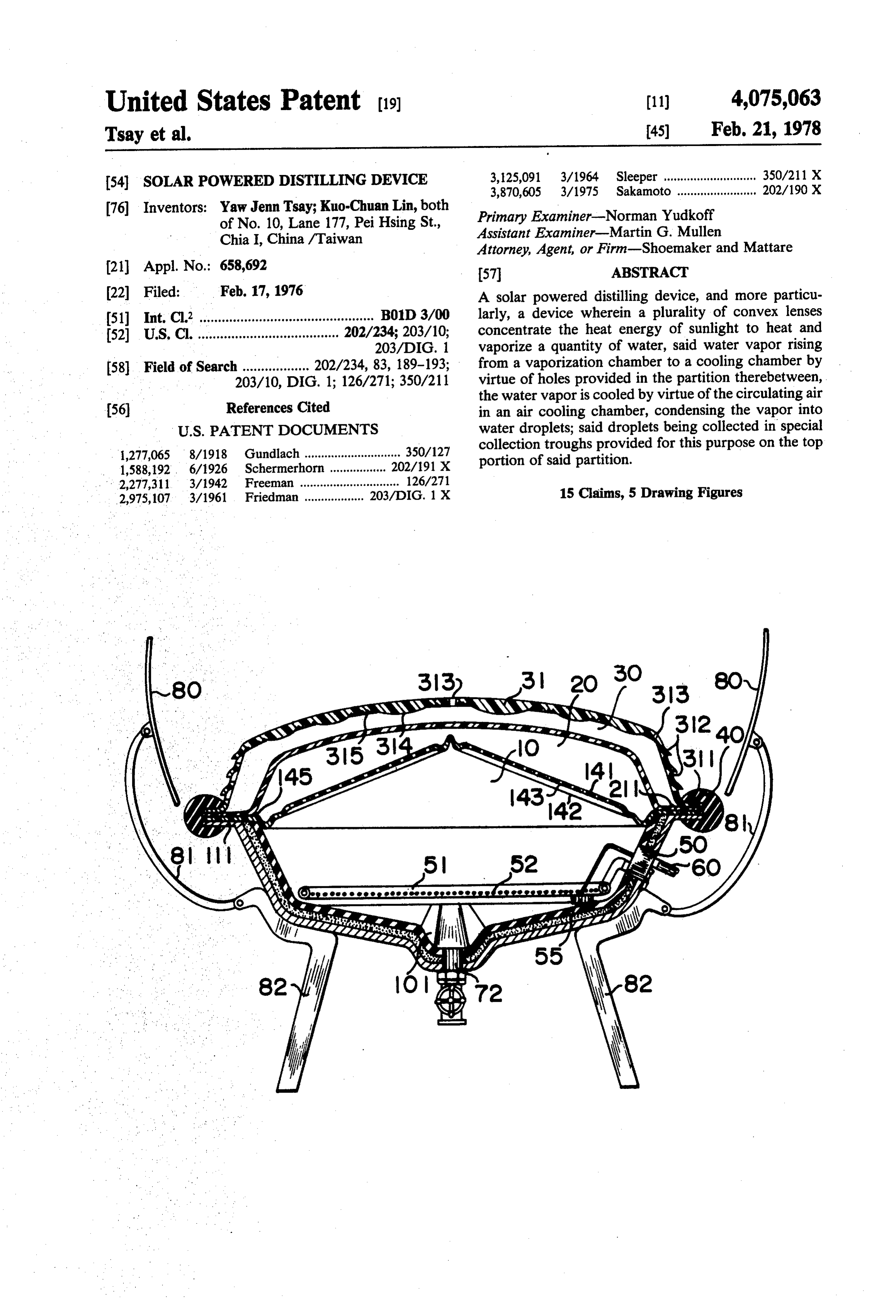
United States Patent (19) (11) 4,075,063 Tsay et al. 45) Feb. 21, 1978 54). SOLAR POWERED DISTILLING DEVICE E:
76 Inventors: Yaw Jenn Tsay; Kuo-Chuan Lin, both ofChiaNo.I, 10, Lane 177, Pei Hsing St.,
Primary Examiner-Norman Yudkoff
Assistant Examiner-Martin G. Mullen
Attorney, Agent, or Firm-Shoemaker and Mattare (21) Appl. No.: 658,692 57 ABSTRACT (22 Filed: Feb. 17, 1976 A solar powered distilling device, and more particu 51) Int. Cl? ............................................... B01D3/00 larly, a device wherein a plurality of convex lenses 52 U.S.C. ...................................... 202/234; 203/10; concentrate the heat energy of sunlight to heat and 203/DIG. 1 vaporize a quantity of water, said water vapor rising 58 Field of Search .................. 202/234, 83, 189-193; from a vaporization chamber to a cooling chamber by 203/10, DIG. 1; 126/271; 350/211 virtue of holes provided in the partition therebetween, the water vapor is cooled by virtue of the circulating air (56) References Cited in an air cooling chamber, condensing the vapor into
1,277,065 8/1918 Gundlach ............................. so collection troughs provided for this purpose on the top 1588192 6/1926 schemerhorn. 20276ix portion of said partition. 2,277,311 3/1942 Freeman .............................. 126/271 2,975,107 3/1961 Friedman .................. 203/DIG. 1 X 15 Claims, 5 Drawing Figures
Page 2
Drawing sheet — no readable text.
Page 3
Drawing sheet — no readable text.
Page 4
tion chamber 20 between the corrugated partition 14
SOLAR POWERED DISTILLENG DEVICE and said condensation plate 21. A transparent lens cover
BACKGROUND OF THE INVENTION
31 is provided over the condensation plate 21 and is supported thereover by virtue of end support sections
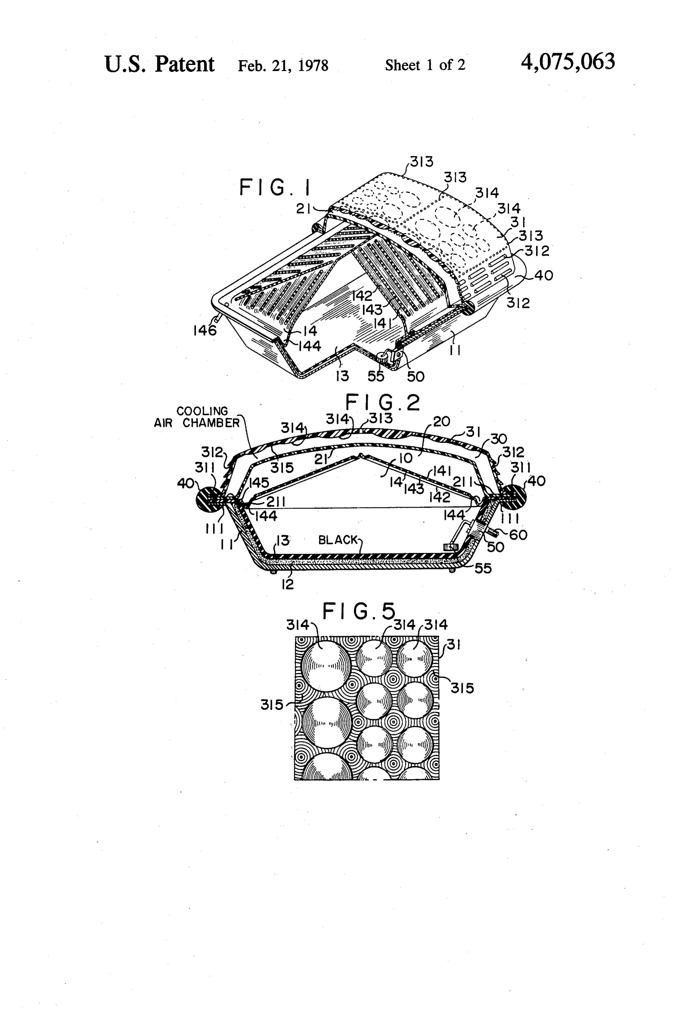
Conventional methods of producing distilled water 5 311 which are supported on top of the end support rely on using electricity or fueled fire to heat cold wa sections 111, 245, and 211. In this way, a cooling air ter. The use of combustable materials or electricity to chamber 30 is formed between the condensation plate produce distilled water is not economically sound. In 21 and the lens cover 31. The end sections are sealed addition, the apparatus involved is generally large and together by means of a rubber or plastic strip 40 which the process quite complex, making the price for such 10 is secured along the periphery of the device. apparatus high. For these reasons, generally only hospi Each downward sloping wall of the lens cover 31 is tals, pharmaceutical and chemical plants are equipped provided with a pluraity of openings or vents 312-312; with means to produce distilled water. It has not been the top portion is provided with a plurality of small possible or economically reasonable for the general holes 313-313. The outer surface of the top portion of public to produce its distilled water in the home. 15 the lens cover 31 is generally smooth. The inner surface The purpose of the present invention is to improve is provided with a plurality of convex lenses 314-314 of the above mentioned defects and to provide an auto various diameters and thicknesses thereon. The spaces matic water distiller of simple construction which is safe between the lenses 314-314 of the lens cover 31 are and convenient and which is not susceptible to malfunc formed in a pluraity of alternately concave and convex tions. 20 annular rings 315-315 to form a ripple like design Another purpose of the present invention is to pro thereon.
vide an automatic water distilling device which may be Water enters the vaporization chamber 10 by means installed on the roof of any home, office school, etc. at of a feed hose 60 and an automatic valve 50. Said auto low cost, or which may be conveniently used on fishing matic valve is provided with a float 55 to open the valve vessels and the like. 25 when the water level falls below a specified level and to close the valve when the water level attains a second
DETAILED DESCRIPTION OF THE specified level.
INVENTION Because the convex lenses 314 are of different sizes Further purposes and advantages of the present in and thicknesses, the heat focus points relative thereto vention will become obvious as it is now explained with 30 will be at different levels in the vaporization chamber 10 reference to the appended drawings wherein: to insure greater efficiency. The rings 315 will cast a FIG. 1 is a perspective view in partial section of an plurality of heat focus points on the surface of the water embodiment of the present invention; and in the air above, thus raising the temperature within FIG. 2 is a cross sectional view thereof; the vaporization chamber 10,
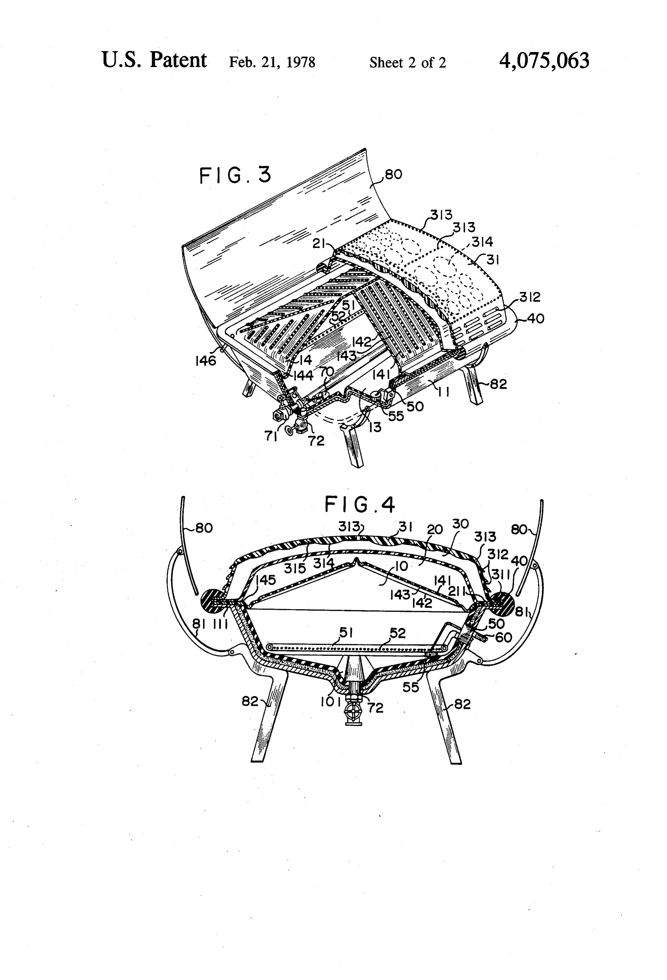
FIG. 3 is a perspective view in partial cross section of 35 When the vaporization chamber 10 is filled with wa another embodiment thereof; ter; the water is heated by virtue of the capacity of the FIG. 4 is a cross sectional view of the same embodi lens cover 31 to cause rays of sunlight to converge at ment as in FIG. 3; various focus points in, on and above the water. As the FIG. 5 is a view of the lens cover according to the water is vaporized, the vapor rises through the partition present embodiments of the present invention. 40 14 by means of the holes 143 provided thereon and into As shown in FIGS. 1, 2 and 5, the water distilling the condensation chamber 20. Cool air enters cooling device according to the present invention is a box-like air chamber 30 by means of the plurality of vents structure. The bottom portion of said structure consists 312-312. As cool air passes between condensation plate of a bottom plate 11 having sides inclined outwardly, 21 and lens cover 31, the temperature of condensation which is made of metal or any suitable material, an 45 plate 21 is maintained at a much lower level than that of insulating layer 12, and a heat absorbing plate 13, which the water vapor, so that when the water vapor comes are layered together to form a vaporizing chamber 10 into contact with the condensation plate 21, it will be which also serves as the reservoir. The heat absorbtion condensed to water droplets. As the water droplets plate is a rubber plate or any suitable material and is of accumulate and increase in size. They will drop from a dark coloring, such as black, dark green, etc., for the 50 the condensation plate 21 onto the corrugated partition purpose of absorbing as much heat as possible to heat 14 below and into the depressed portions 142 thereof, the water. The insulating layer 12 may be made of poly wherefrom the accumulated water will flow down styrene foam or any suitable insulating material to iso wards and into the trough 144. The distilled water will late the inside of the vaporizing chamber 10 from the then flow through a hose 146 and into a receptacle not outside temperature. The upper portion of the vaporiz- 55 included in the scope of the present invention and not ing chamber 10 is covered by a prism shaped corrugated shown in the appended drawings.
partition 14 which is transparent and slopes downward FIGS. 3 & 4 show another embodiment of the present in all directions. The bottom of all sides of the partition invention which is essentially as that described above, 14 end in a water collecting trough 144. A plurality of but which is adapted to distill sea of salt water so that it holes 143-143 of suitable size & shape are provided 60 may be used on small or large fishing vessels or the like. through the raised portions 141 of the corrugated parti According to this embodiment, the bottom of the de tion 14. The bottom of the depressed portions 142 of vice is angular, sloping down towards the center from said partition meet with the water trough 144. The both sides. The center or lowest portion thereof is pro periphery of the corrugated partition 14 is provided vided with a trough 101, said trough 101 being provided with end support sections 145 which are supported on 65 with a float 70 to automatically open an outlet 71 when the end support sections 111 of the bottom plate 11; and the quantity of water falls to a specified level. In this supported thereon are the end support sections 211 of a way, the remaining water, which will contain a high transparent condensation plate 21, forming a condensa density of salt, may be drained from the vaporization
Page 5
chamber 10. As the salt may tend to crystallize on the energy at different levels in said vaporization sloping bottom surface, water pipes 51-51 are provided chamber, thereby focusing solar energy into, on along the bottom periphery of the vaporization cham and above water in said vaporization chamber; ber 10. These pipes are connected to each other in a air inlet means on said cover for conducting cooling suitable fashion and inturn connected to the inlet valve air into said cooling air chamber to contact said 50, so that when the valve 50 is opened, the water will condensation plate one side for maintaining said enter the vaporization chamber 10 from all sides by plate at a temperature below the condensation tem virtue of holes 52-52, washing any remaining salt crys perature of the fluid in said vaporization chamber tals down to the trough 101. To remove these salt crys so that vapor formed in said vaporization chamber tals from the vaporization chamber 10, a larger outlet 10 is condensed into condensate upon contact with valve 72 is provided at the bottom of the trough 101. said plate other side; Either of the two embodiments described above may a condensate collecting means connected to said tray be provided with reflecting mirrors 80 which may be for collecting the condensate formed on said con attached to a base 82 by means of a pivotedly connected densation plate; and w mirror brace 81. By virtue of the arched surface of the 15 outlet means connected to said condensate collecting mirror 80, the maximum effectiveness may be derived means for withdrawing the collected condensate from direct and indirect sunlight. from said condensate collecting means. Experiments by the present inventor have shown that 2. The device of claim 1 wherein the holes are located a device as described above, 3 feet X 4 feet X 1 feet 4 in peaks in said corrugated partition. inches will produce 5 liters of distilled water in a 24 20 3. The device of claim 2 wherein valleys in said cor hour period on overcast winter days, and over 30 liters rugated partition are fluidly connected to said conden in the same amount of time during sunney summer sate collecting means.
weather. 4. The device of claim 1 wherein said air inlet means The distilled water produced by this method has been tested and found to be as healthful as distilled water 25 includes vents defined in said cover. 5. The device of claim 1 wherein said fluid inlet produced by conventional means. means includes a float valve.
What I claim is:
1. A distilling device powered by solar energy com 6. The device of claim 1 wherein said lenses are lo prising: cated inside said cooling air chamber. a tray for defining a vaporization chamber; 30 7. The device of claim 1 wherein said lenses are con Wex.
a transparent cover on said tray;
a transparent condensation plate mounted on said 8. The device of claim 1 wherein said partition is tray; angular with a peak portion defined centrally thereof. 9. The device of claim 1 wherein said tray is a box a transparent corrugated partition mounted on said like structure.
tray between said tray and said condensation plate 35 so that a top side of said partition defines a conden 10. The device defined in claim 1, further including at sation chamber with a bottom side of said conden least one reflecting mirror connected to said housing to sation plate and a bottom side of said partition increase the amount and intensity of heat from the sun defines a vaporization chamber with said tray, said to the plurality of lenses.
condensation plate being mounted between said 11. The device of claim.1 further including a plurality partition and said cover so that a top side of said of focusing rings located on said cover for focusing condensation plate defines a cooling air chamber solar energy into said vaporization chamber at various with a bottom side of said cover, said partition locations on the surface of the fluid located in said va having a multiplicity of holes defined therein, that porization chamber.
portion of said tray forming said vaporization 45 12. The device of claim 11 wherein said rings are chamber with said partition having attached located in the spaces between said lenses.
thereto a layer of insulating material; 13. The device of claim 11 wherein, said rings are fluid inlet means on said tray for conducting fluid to alternately concave and convex. a be vaporized into said vaporization chamber; 14. The device of claim 1 further including cleansing a plurality of differential focal length solar energy 50 means positioned in said tray to be located in said vapor focusing lenses on said cover focusing solar energy ization chamber for circulating drainage fluid there through said cooling air and condensation cham through to cleanse said vaporization chamber. bers and said partition and said condensation plate 15. The device defined in claim 14 wherein said onto the fluid located in said vaporization chamber cleansing means is located near the center of the bottom to form vapor which passes through the holes in 55 portion of said vaporization chamber and includes a said partition from said vaporization chamber into trough and suitable valves to effect draining of water said condensation chamber, said leases having a and removal of salt crystals therefrom.
plurality of different focal lengths to focus solar
Provenance
- Collection
- Cited prior art
- Original PDF
- patentimages.storage.googleapis.com →
- Filed
- 1976-02-17
- Pages
- 5
- Method
- pdftotext (the PDF's own text layer) + pdftoppm 300dpi page scans
- Source
- Google Patents bibliographic record
- Granted
- 1978-02-21
- Inventors
- Yaw Jenn Tsay; Kuo-Chuan Lin
- Transcribed from
- patentimages.storage.googleapis.com →