patent · US3351538
Solar distillation equipment
7 November 1967
Page 1
Drawing sheet — no readable text.
Page 2
Drawing sheet — no readable text.
Page 3
United States Patent Office 3,351,538 Patented Nov. 7, 1967
3,351,538 It is a further object of the invention to provide porta SOLAR DISTILLATION EQUPMENT ble equipment for use in effecting the evaporation of Stella Andrassy, Ridge Road, Kingston, N.J. 08528 fresh water from salt water, or for drying articles or prod Filed June 18, 1963, Ser. No. 288,714 lucts containing excess moisture.
8 Claims. (CI. 202-234) 5 These and other objects and features of the present This invention relates to methods and means for utiliz invention will appear from the following description thereof wherein ing solar radiation for the purpose of evaporating liquids. accompanying drawings. reference is made to the figures of the Many different types of solar stills have been designed In the drawings:
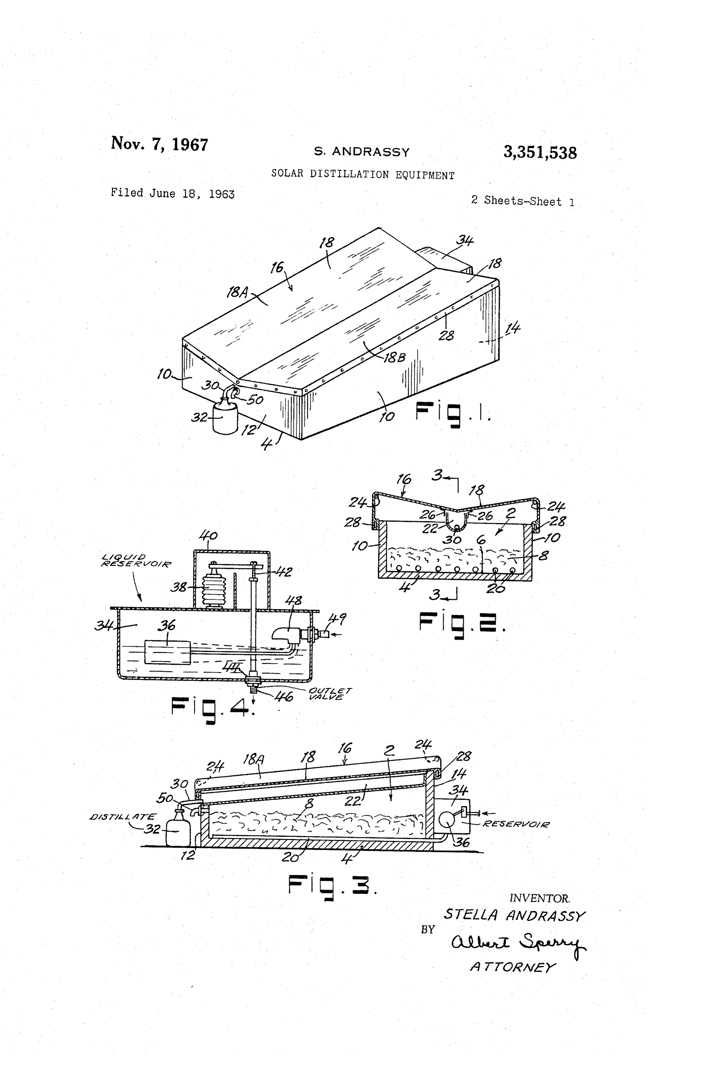
and tested heretofore primarily for the purpose of obtain ing fresh water from salt water. For this purpose, it is 0 of FIG. 1 is a perspective view of a typical embodiment the present invention;
usual to provide the solar still with a black porous fabric FIG. 2 is a transverse sectional view of a construction to which the salt water is supplied by drainage from an shown in FIG. 1;
upper supply chamber or by wicking from a lower salt FIG. 3 is a longitudinal sectional view of a construc Water Source. tion shown in FIGS. 1 and 2 taken on the line 3-3 of The fabric thus supplied with the liquid to be distilled FIG. 2;
generally is exposed to solar radiation through a trans parent cover or enclosure whereby the pure water dis trolFIG. 4 is a sectional view of a typical form of con means which may be employed in accordance with tilled off from the salt water or liquid is caused to collect the present invention;
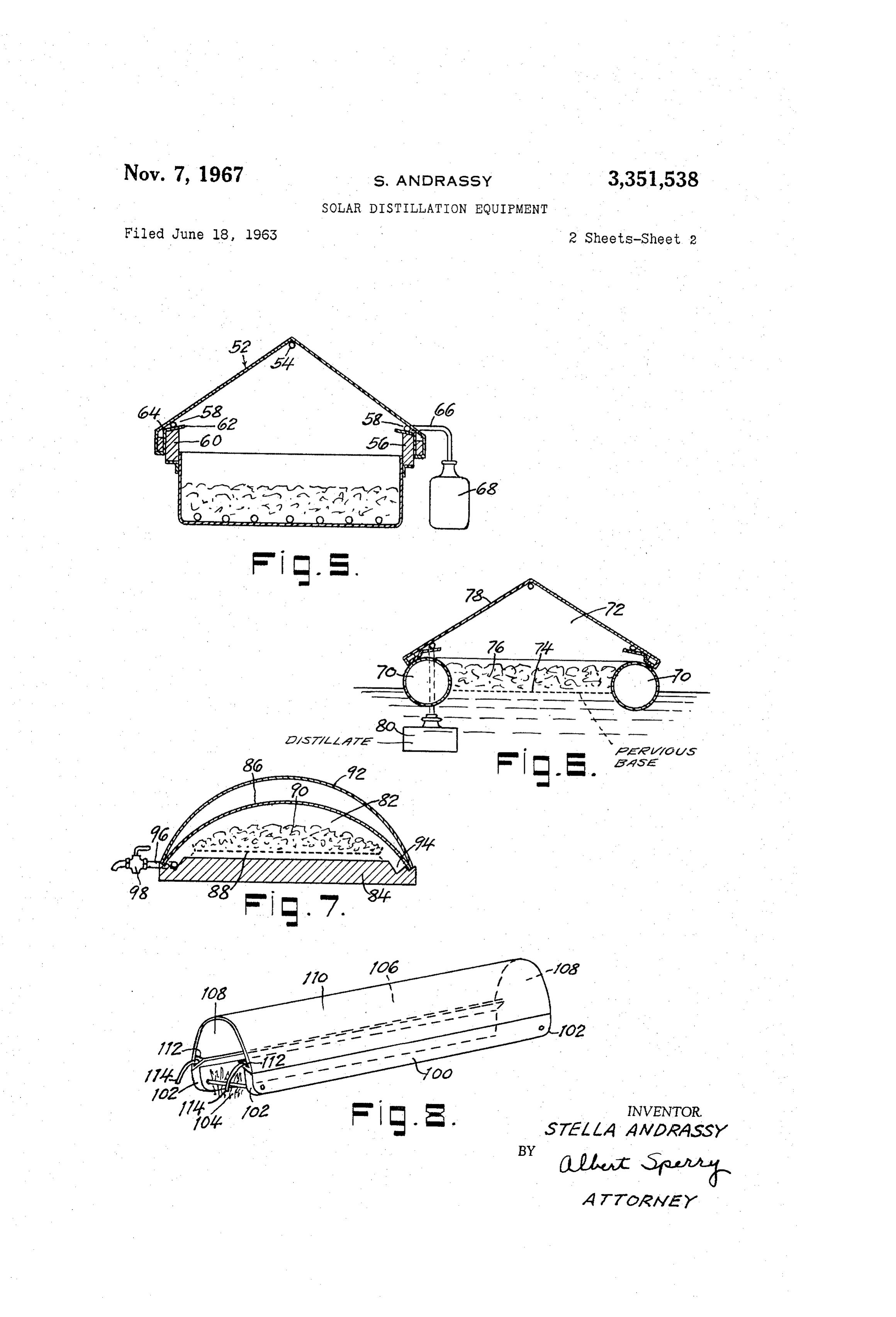
and deposit on the inner surface of the transparent en FIGS. 5, 6 and 7 are sectional views of alternative closure. The distilled water thus obtained is caused to 20 embodiments of the present invention; and run down the inner surface of the transparent enclosure so that it can be collected and used for drinking purposes tiveFIG. form 8 is a perspective illustrating a further alterna of the present invention.
or for irrigation or any other use desired. In that form of the invention chosen for purposes of While such constructions operate successfully, it is illustration in FIGS. 1 and 2 of the drawings, the solar found in practice that the yield of the distilled water ob 25 distillation apparatus is provided with a transparent film tained per square foot of exposed area of the still is rela or sheet of material through which the rays of the sun tively limited. Furthermore, the black fabric or felt ordi may penetrate. In a typical employment of the present narily used as the wicking material to receive and hold invention, the transparent material employed is glass or salt water during the distillation process tends to collect 30 a plastic material such as the polyvinyl flouride composi mold or fungi which weaken the fabric with the result that the felt or wicking has to be replaced from time to tions sold under the trade names "Tedlar' and “Mylar.” However, other transparent materials may be employed.
time.
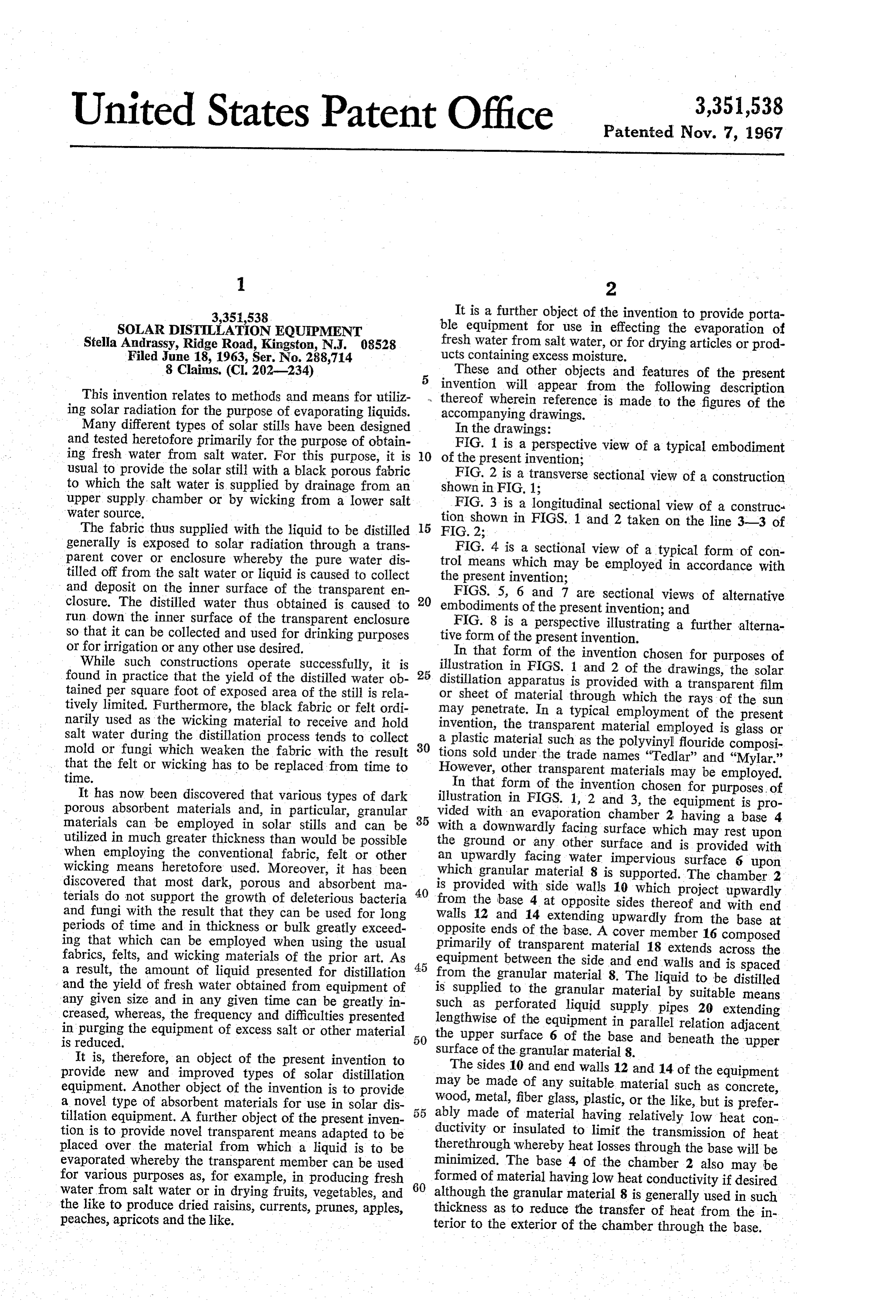
It has now been discovered that various types of dark In that form of the invention chosen for purposes of porous absorbent materials and, in particular, granular vided illustration in FIGS. 1, 2 and 3, the equipment is pro materials can be employed in solar stills and can be 35 With awith an evaporation chamber 2 having a base 4 utilized in much greater thickness than would be possible the ground or any facing downwardly other surface which may rest upon surface and is provided with when employing the conventional fabric, felt or other an upwardly facing water impervious surface 6 upon wicking means heretofore used. Moreover, it has been which granular material 8 is supported. The chamber 2 discovered that most dark, porous and absorbent ma 40 is provided with side walls 10 which project upwardly terials do not support the growth of deleterious bacteria from the base 4 at opposite sides thereof and with end and fungi with the result that they can be used for long Walls 12 and 14 extending upwardly from the base at periods of time and in thickness or bulk greatly exceed ing that which can be employed when using the usual primarilyends opposite of the base. A cover member 16 composed of transparent material 18 extends across the fabrics, felts, and wicking materials of the prior art. As 45 equipment between the side and end walls and is spaced a result, the amount of liquid presented for distillation and the yield of fresh water obtained from equipment of isfrom the granular material 8. The liquid to be distilled Supplied to the granular material by suitable means any given size and in any given time can be greatly in Such as perforated liquid supply pipes 20 extending creased, whereas, the frequency and difficulties presented lengthwise of the equipment in parallel relation adjacent in purging the equipment of excess salt or other material 50 the is reduced. upper surface 6 of the base and beneath the upper It is, therefore, an object of the present invention to Surface of the granular material 8. provide new and improved types of solar distillation The sides 10 and end walls 12 and 14 of the equipment equipment. Another object of the invention is to provide may be made of any suitable material such as concrete, a novel type of absorbent materials for use in solar dis 55 Wood, metal, fiberglass, plastic, or the like, but is prefer. tillation equipment. A further object of the present inven ably made of material having relatively low heat con tion is to provide novel transparent means adapted to be ductivity or insulated to limit the transmission of heat placed over the material from which a liquid is to be therethrough whereby heat losses through the base will be evaporated whereby the transparent member can be used minimized. The base 4 of the chamber 2 also may be for various purposes as, for example, in producing fresh 60 formed of material having low heat conductivity if desired water from salt water or in drying fruits, vegetables, and although the granular material 8 is generally used in such the like to produce dried raisins, currents, prunes, apples, thickness as to reduce the transfer of heat from the in peaches, apricots and the like. terior to the exterior of the chamber through the base.
Page 4
The chamber 2 may, of course, be of any desired size As a result, such a transparent sheet retains its uniform depending upon the quantity of liquid to be distilled and clarity during use, and water or other liquid condensing the yield of fresh water desired. Its size also will depend thereon is discharged readily therefrom to the receivers. upon whether the equipment is designed to be portable or The usual fogging or accumulation of droplets on the in is a permanent installation. ner surface of the transparent sheet material is thereby re The granular material 8 which is supported on the sur duced, and diffusion of the solar radiation or absorption face 6 of the base may vary in size from about one inch to or diminution thereof in passing through the transparent about 42 of an inch or finer and is preferably of a rela material is effectively reduced. Moreover, the tendency tively porous nature presenting extended surface area for for the water which condenses on the inner surface of the absorption and distribution of the liquid to be distilled. 10 the transparent material to remain on the sheet and un Typical of such materials are organic materials such as dergo re-evaporation is materially reduced and the capac peat moss, charcoal, balsa or other wood particles in the ity or efficiency of the equipment is materially increased. form of wood chips, shavings, sawdust, or the like. In the In practice, it has been found that very effective wet alternative, the particles may be formed of porous inor tability can be imparted to the inner surface of vinyl ganic material such as brick lava, pumice, silica gel, sand 15 plastic sheet material by placing such material on a soft stone, porous limestone, or the like. If desired, mixtures surface, wetting the surface with water, and rubbing the of such materials may be employed. The granular material surface with fine sand paper using a circular motion. is preferably black or dark in color and, if desired, it may The desired degree of roughness which will assure ef be dyed or otherwise treated to render it dark in color so when fective wettability of the sheet will then become apparent as to increase its heat absorbing and/or its water absorb 20 the water on the surface of the sheet spreads out ing properties. into a continuous film and no longer accumulates in The depth of the layer of granular material can be droplets on the abraded surface. However, if preferred, varied considerably depending upon the intensity of the the surface of the transparent material may be roughened solar radiation, the position of the surface of the granular or abraded in other ways, and either resinous, glass or material with respect to the sun, the nature of the liquid 25 other transparent material employed may be suitably supplied to the equipment, the type of granular material treated with an agent such as ammonia or a mild alkali employed, the form and construction of the equipment, or other material which serves to cause liquids to spread and similar factors. For most purposes, peat moss is pre out when they contact the surface. However, most sur ferred and the depth of the layer of granular material face-treating agents thus employed tend to loose their should be not less than about one inch or more than about 30 effectiveness in a limited time due to the dissolving or 8 inches. The preferred depth of the granular material Washing away thereof or for other reasons. when employing peat moss is from about 3 to 6, particu In using equipment of the character described, the larly when the equipment is used to obtain fresh water granular material within the chamber is first thoroughly from sea water. Wetted with sea water, or other liquid to be distilled, prior The transparent material 18 which extends over the 35 to initiating operation of the equipment. For this purpose, granular material may be formed of plastic, glass or any the transparent cover member 16 may be removed and other suitable material through which solar radiation may the granular material 8 sprayed with the liquid until it is be readily transmitted to the granular material. The trans Substantially Saturated. Liquid may also be supplied to the parent material is inclined so as to cause liquid condens granular material adjacent the base 2 of the equipment ing on the inner surface thereof to flow downward on the 40 through the liquid supply pipes 20. The cover member inner surface to a liquid receiving channel 22. As shown is then replaced so as to fit closely about the sides 10 in FIGS. 1 and 2, the transparent material 18 is supported and end Walls 12 and 14 in order to enclose and house in an elevated position at its opposite sides by means of the Wetted granular material preventing the circulation of rods or other supporting members 24. The central portion air through the chamber during the distillation operation. of the cover 16 is held at a lower elevation by suitable Additional Water is supplied to the granular material from means or by the weight of the trough-like liquid receiving a reservoir 34 or other source connected to the pipes 20 channel 22. The channel 22 may then be attached to the to maintain the granular material wet or moist as the transparent material 18 by tapes 26 or by any other suit operation continues.
able means. The surfaces 18A and 18B of the transparent The equipment is positioned either horizontally or suit material, therefore, will be inclined transversely of the 50 ably inclined to allow Sunlight and solar radiation to pass chamber 2 and toward the center of the chamber. The op through the transparent material 18 to be absorbed by posite sides and the ends of the transparent material ex the granular material 8. In this way, the temperature of tend downward about the outer edges of a frame 28 which the granular material and the sea water or other liquid in fits closely around the sides and ends of the chamber. The contact with the granular material is raised sufficiently edges of the transparent material may be secured to the 55 to cause fresh Water to be distilled therefrom in the form frame 28 by nails, staples, cement or any other suitable of water vapor. The water vapor evaporating from the material. The liquid receiving channel 22 is preferably bed of granular material then condenses on the inner sur. inclined lengthwise of the equipment to aid in directing face of the sheet of transparent material. The film or the distillate to one end thereof, and a discharge tube 30 droplets of condensed water then run down the inner sur communicates with the channel 22 for directing the fresh 60 faces of the slanting sides 18A and 18B of the cover to water or distillate to a vessel 32 or to other means for re the centrally located liquid receiving channel 22, and the ceiving or using the distillate produced. fresh water thus collected is discharged from the equip In a preferred form of the invention, the transparent net through the discharge tubes 30 to the vessel 32 or cover material i8 is formed of a plastic composition such other means for collecting or using the fresh water. as a polyvinyl resin sheet material and the inner Surface of 65 As the operation continues, additional saltwater Or the sheet on which the water or distillate is to condense other liquid to be distilled is Supplied to the granular ma is pretreated to render the surface thereof slightly rough, terial 8 from the reservoir 34 or from any other desired irregular or “wettable.” Thus, it has been found that when Source and is Supplied to the perforated pipes 20. This the surface of a plastic vinyl resin sheet is rubbed with an Supply is preferably controlled so as to prevent flooding abrasive material, such as fine sand paper, emery cloth, 70 of the granular material while assuring the continual wet steel wool, a fine grained grinding wheel, or the like while ting or moistening thereof. Thus, a float ball 36 or the the surface of the sheet is wet, any liquid condensing on like may be provided in the reservoir 34 and the reser the roughened surface of the sheet tends to spread out into voir may be positioned to maintain the desired flow or a thin film or to flow evenly over the surface of the sheet level liquid in the lower portion of the granular material. instead of accumulating in the form of droplets thereon. 75 In the alternative, the supply of liquid to the granular
Page 5
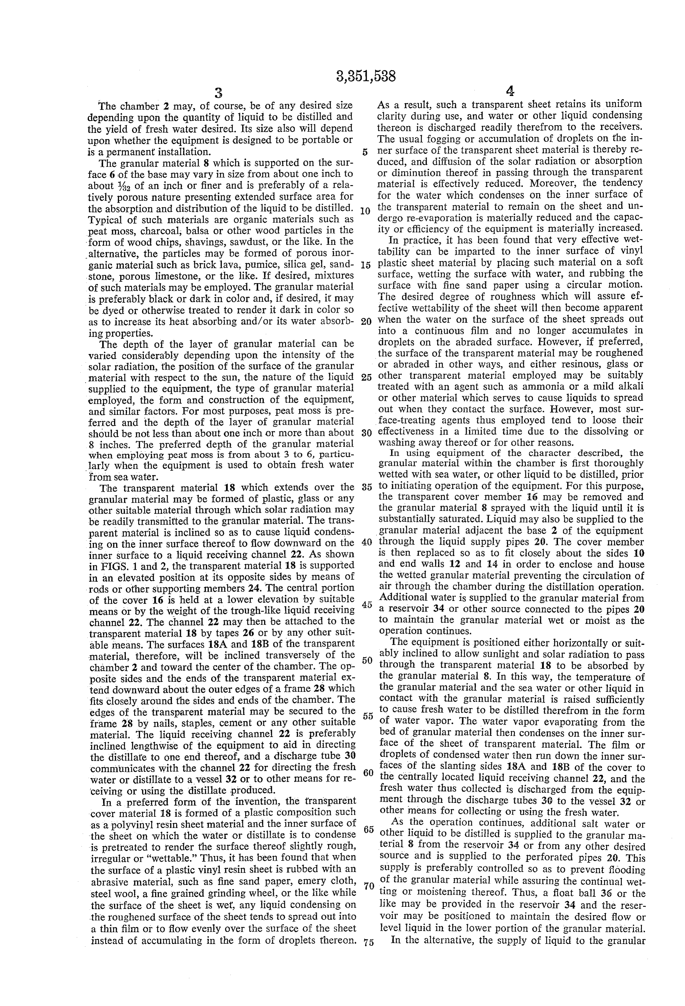
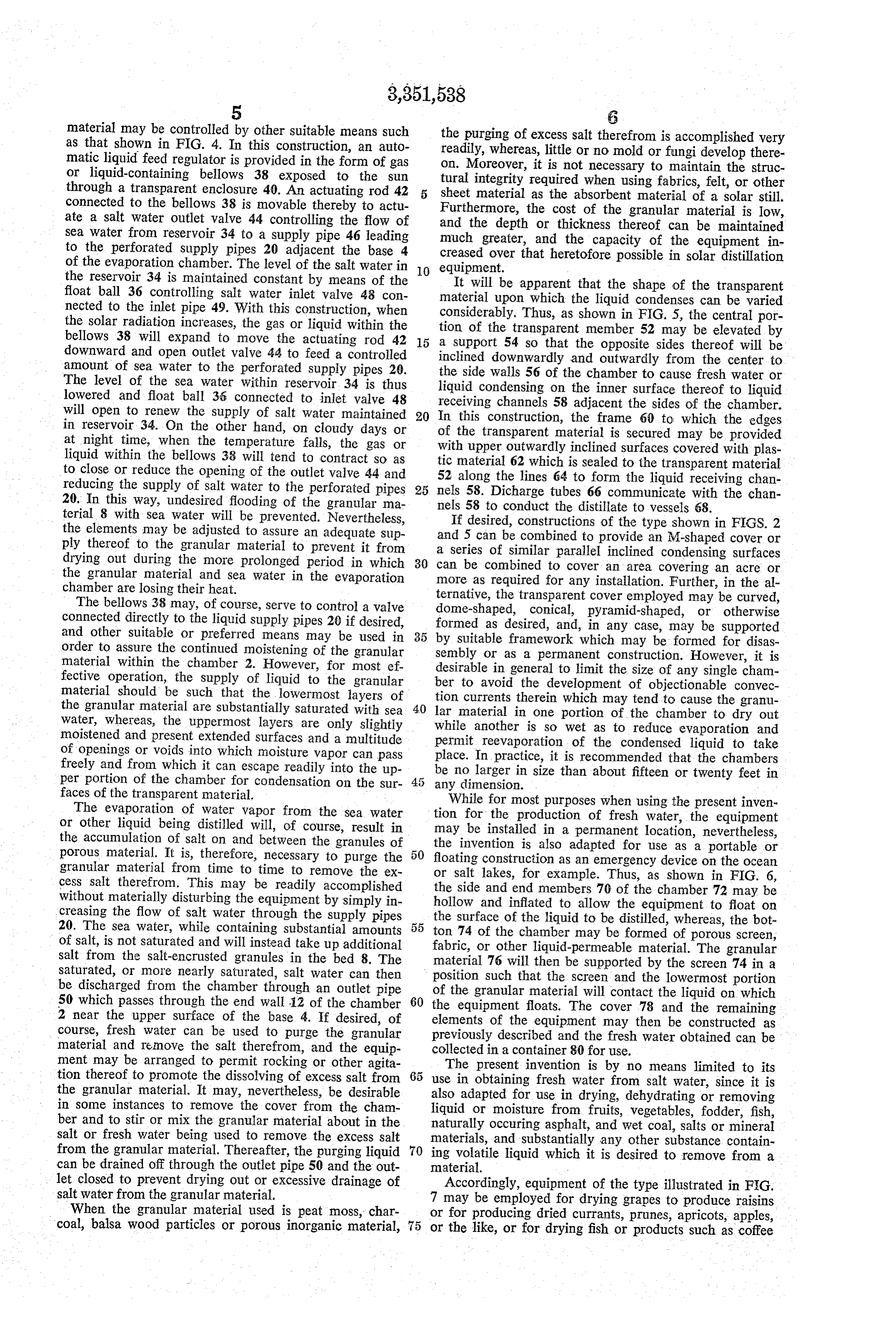
material may be controlled by other suitable means such the purging of excess salt therefrom is accomplished very as that shown in FIG. 4. In this construction, an auto readily, whereas, little or no mold or fungi develop there matic liquid feed regulator is provided in the form of gas on. Moreover, it is not necessary to maintain the struc or liquid-containing bellows 38 exposed to the sun tural integrity required when using fabrics, felt, or other through a transparent enclosure 40. An actuating rod 42 sheet material as the absorbent material of a solar still. connected to the bellows 38 is movable thereby to actu ate a salt water outlet valve 44 controlling the flow of and the depththeor cost
Furthermore, of the granular material is low, thickness thereof can be maintained sea water from reservoir 34 to a supply pipe 46 leading much greater, and the capacity of the equipment in to the perforated supply pipes 20 adjacent the base 4 creased over that heretofore possible in solar distillation of the evaporation chamber. The level of the salt water in 10 equipment.
the reservoir 34 is maintained constant by means of the It will be apparent that the shape of the transparent float ball 36 controlling salt water inlet valve 48 con material upon which the liquid condenses can be varied nected to the inlet pipe 49. With this construction, when considerably. Thus, as shown in FIG. 5, the central por the solar radiation increases, the gas or liquid within the tion of the transparent member 52 may be elevated by bellows 38 will expand to move the actuating rod 42 5 a support 54 so that the opposite sides thereof will be downward and open outlet valve 44 to feed a controlled inclined downwardly and outwardly from the center to amount of sea water to the perforated supply pipes 20. the side walls 56 of the chamber to cause fresh water or The level of the sea water within reservoir 34 is thus liquid condensing on the inner surface thereof to liquid lowered and float ball 36 connected to inlet valve 48 receiving channels 58 adjacent the sides of the chamber. will open to renew the supply of salt water maintained 20 In this construction, the frame 60 to which the edges in reservoir 34. On the other hand, on cloudy days or of the transparent material is secured may be provided at night time, when the temperature falls, the gas or with upper outwardly inclined surfaces covered with plas liquid within the bellows 38 will tend to contract so as tic material 62 which is sealed to the transparent material to close or reduce the opening of the outlet valve 44 and 52 along the lines 64 to form the liquid receiving chan reducing the supply of salt water to the perforated pipes 25 nels 58. Dicharge tubes 66 communicate with the chan 20. In this way, undesired flooding of the granular ma nels 58 to conduct the distillate to vessels 68. terial 8 with sea water will be prevented. Nevertheless, If desired, constructions of the type shown in FIGS. 2 the elements may be adjusted to assure an adequate sup and 5 can be combined to provide an M-shaped cover or ply thereof to the granular material to prevent it from a series of similar parallel inclined condensing surfaces drying out during the more prolonged period in which 30 can be combined to cover an area covering an acre or the granular material and sea water in the evaporation more as required for any installation. Further, in the al chamber are losing their heat. ternative, the transparent cover employed may be curved, The bellows 38 may, of course, serve to control a valve dome-shaped, conical, pyramid-shaped, or otherwise connected directly to the liquid supply pipes 20 if desired, formed as desired, and, in any case, may be supported and other suitable or preferred means may be used in by suitable framework which may be formed for disas order to assure the continued moistening of the granular sembly or as a permanent construction. However, it is material within the chamber 2. However, for most ef desirable in general to limit the size of any single cham fective operation, the supply of liquid to the granular ber to avoid the development of objectionable convec material should be such that the lowermost layers of the granular material are substantially saturated with sea 40 tion currents therein which may tend to cause the granu lar material in one portion of the chamber to dry out water, whereas, the uppermost layers are only slightly while another is so wet as to reduce evaporation and moistened and present extended surfaces and a multitude of openings or voids into which moisture vapor can pass place. Inreevaporation permit of the condensed liquid to take practice, it is recommended that the chambers freely and from which it can escape readily into the up be no larger in size than about fifteen or twenty feet in per portion of the chamber for condensation on the sur any dimension.
faces of the transparent material.
The evaporation of water vapor from the sea water tionWhile for for most purposes when using the present inven the production of fresh water, the equipment or other liquid being distilled will, of course, result in may be installed in a permanent location, nevertheless, the accumulation of salt on and between the granules of porous material. It is, therefore, necessary to purge the 50 the invention is also adapted for use as a portable or floating construction as an emergency device on the ocean granular material from time to time to remove the ex cess salt therefrom. This may be readily accomplished the salt or side lakes, for example. Thus, as shown in FIG. 6, and end members 70 of the chamber 72 may be without materially disturbing the equipment by simply in hollow and inflated to allow the equipment to float on creasing the flow of salt water through the supply pipes the surface of the liquid to be distilled, whereas, the bot 20. The sea water, while containing substantial amounts 55 ton 74 of the chamber may be formed of porous screen, of salt, is not saturated and will instead take up additional fabric, or other liquid-permeable material. The granular salt from the salt-encrusted granules in the bed 8. The material 76 will then be supported by the screen 74 in a saturated, or more nearly saturated, salt water can then position such that the screen and the lowermost portion be discharged from the chamber through an outlet pipe of the granular material will contact the liquid on which 50 which passes through the end wall 12 of the chamber 60 the equipment floats. The cover 78 and the remaining 2 near the upper surface of the base 4. If desired, of elements of the equipment may then be constructed as course, fresh water can be used to purge the granular previously described and the fresh water obtained can be material and remove the salt therefrom, and the equip collected in a container 80 for use.
ment may be arranged to permit rocking or other agita tion thereof to promote the dissolving of excess salt from 65 useThe present invention is by no means limited to its in obtaining fresh water from salt water, since it is the granular material. It may, nevertheless, be desirable also adapted for use in drying, dehydrating or removing in some instances to remove the cover from the cham liquid or moisture from fruits, vegetables, fodder, fish, ber and to stir or mix the granular material about in the naturally occuring asphalt, and wet coal, salts or mineral salt or fresh water being used to remove the excess salt materials, and substantially any other substance contain from the granular material. Thereafter, the purging liquid 70 can be drained off through the outlet pipe 50 and the out ing volatile liquid which it is desired to remove from a material.
let closed to prevent drying out or excessive drainage of Accordingly, equipment of the type illustrated in FIG. saltwater from the granular material. 7 may be employed for drying grapes to produce raisins When the granular material used is peat moss, char or for producing dried currants, prunes, apricots, apples, coal, balsa wood particles or porous inorganic material, 75 or the like, or for drying fish or products such as coffee
Page 6
y 3.
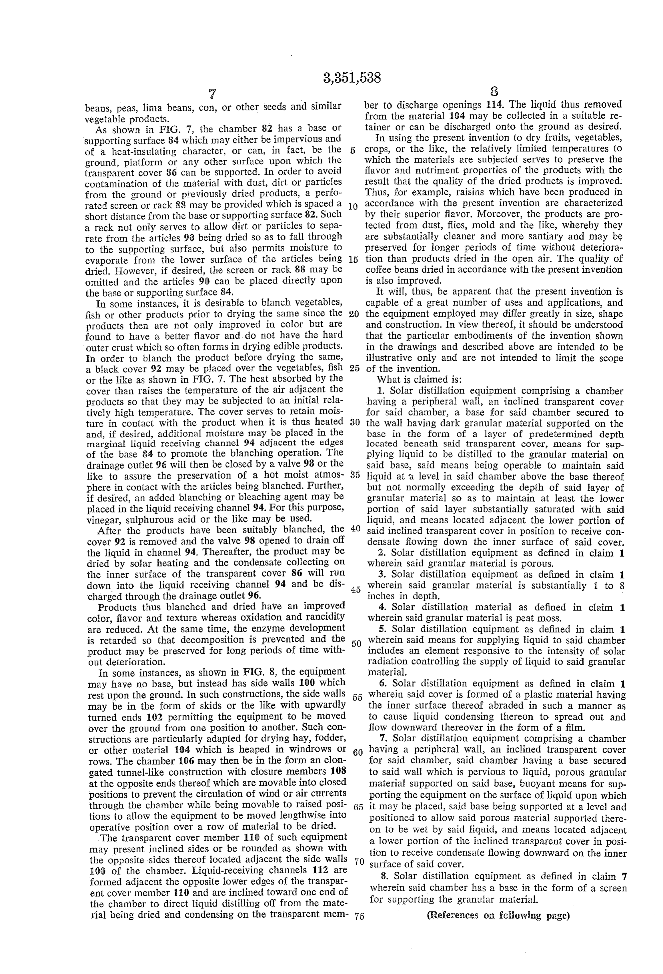
beans, peas, lima beans, con, or other Seeds and similar ber to discharge openings 1:4. The liquid thus removed vegetable products. from the material 104 may be collected in a suitable re As shown in FIG. 7, the chamber 82 has a base or tainer or can be discharged onto the ground as desired. supporting surface 84 which may either be impervious and In using the present invention to dry fruits, vegetables, of a heat-insulating character, or can, in fact, be the 5 crops, or the like, the relatively limited temperatures to ground, platform or any other surface upon which the which the materials are subjected serves to preserve the transparent cover 86 can be supported. In order to avoid flavor and nutriment properties of the products with the contamination of the material with dust, dirt or particles result that the quality of the dried products is improved. from the ground or previously dried products, a perfo Thus, for example, raisins which have been produced in rated screen or rack 88 may be provided which is spaced a 10 accordance with the present invention are characterized short distance from the base or supporting surface 82. Such by their superior flavor. Moreover, the products are pro a rack not only serves to allow dirt or particles to Sepa tected from dust, flies, mold and the like, whereby they rate from the articles 90 being dried so as to fall through are substantially cleaner and more Santiary and may be to the supporting surface, but also permits moisture to preserved for longer periods of time without deteriora evaporate from the lower Surface of the articles being tion than products dried in the open air. The quality of dried. However, if desired, the screen or rack 88 may be coffee beans dried in accordance with the present invention omitted and the articles 99 can be placed directly upon is also improved.
the base or Supporting surface 84. It will, thus, be apparent that the present invention is In some instances, it is desirable to blanch vegetables, capable of a great number of uses and applications, and fish or other products prior to drying the same since the 20 the equipment employed may differ greatly in size, shape products then are not only improved in color but are and construction. In view thereof, it should be understood found to have a better flavor and do not have the hard that the particular embodiments of the invention shown outer crust which so often forms in drying edible products. in the drawings and described above are intended to be In order to blanch the product before drying the same, illustrative only and are not intended to limit the scope a black cover 92 may be placed over the vegetables, fish 25 of the invention.
or the like as shown in FIG. 7. The heat absorbed by the What is claimed is:
cover than raises the temperature of the air adjacent the . Solar distillation equipment comprising a chamber products so that they may be subjected to an initial rela having a peripheral wall, an inclined transparent cover tively high temperature. The cover serves to retain mois for said chamber, a base for said chamber secured to ture in contact with the product when it is thus heated 30 the wall having dark granular material supported on the and, if desired, additional moisture may be placed in the base in the form of a layer of predetermined depth marginal liquid receiving channel 94 adjacent the edges located beneath said transparent cover, means for sup of the base 84 to promote the blanching operation. The plying liquid to be distilled to the granular material on drainage outlet 96 will then be closed by a valve 98 or the said base, said means being operable to maintain said like to assure the preservation of a hot moist atmos liquid at a level in said chamber above the base thereof phere in contact with the articles being blanched. Further, but not normally exceeding the depth of said layer of if desired, an added blanching or bleaching agent may be granular material so as to maintain at least the lower placed in the liquid receiving channel 94. For this purpose, portion of said layer substantially saturated with said vinegar, sulphurous acid or the like may be used. liquid, and means located adjacent the lower portion of After the products have been suitably blanched, the 40 said inclined transparent cover in position to receive con cover 92 is removed and the valve 98 opened to drain off densate fiowing down the inner surface of said cover. the liquid in channel 94. Thereafter, the product may be 2. Solar distillation equipment as defined in claim 1 dried by solar heating and the condensate collecting on wherein said granular material is porous. the inner surface of the transparent cover 86 will run 3. Solar distilation equipment as defined in claim 1 down into the liquid receiving channel 94 and be dis wherein said granular material is substantially 1 to 8 charged through the drainage outlet 96. inches in depth.
Products thus blanched and dried have an improved 4. Solar distillation material as defined in claim 1 color, flavor and texture whereas oxidation and rancidity wherein said granular material is peat moss. are reduced. At the same time, the enzyme development 5. Solar distillation equipment as defined in claim 1 is retarded so that decomposition is prevented and the wherein said means for Supplying liquid to said chamber product may be preserved for long periods of time with includes an element responsive to the intensity of solar out deterioration. radiation controlling the Supply of liquid to said granular In some instances, as shown in FIG. 8, the equipment material.
may have no base, but instead has side walls 100 which 6. Solar distillation equipment as defined in claim 1 rest upon the ground. In such constructions, the side walls 55 wherein said cover is formed of a plastic material having may be in the form of skids or the like with upwardly the inner surface thereof abraded in such a manner as turned ends 102 permitting the equipment to be moved to cause liquid condensing thereon to spread out and over the ground from one position to another. Such con flow downward thereover in the form of a film. structions are particularly adapted for drying hay, fodder, 7. Solar distillation equipment comprising a chamber or other material 104 which is heaped in windrows or 60 having a peripheral wall, an inclined transparent cover rows. The chamber 106 may then be in the form an elon for said chamber, said chamber having a base secured gated tunnel-like construction with closure members 108 to said wall which is pervious to liquid, porous granular at the opposite ends thereof which are movable into closed material Supported on said base, buoyant means for sup positions to prevent the circulation of wind or air currents porting the equipment on the Surface of liquid upon which through the chamber while being movable to raised posi it may be placed, said base being Supported at a level and tions to allow the equipment to be moved lengthwise into positioned to allow said porous material supported there operative position over a row of material to be dried. on to be wet by Said liquid, and means located adjacent The transparent cover member 110 of such equipment a lower portion of the inclined transparent cover in posi may present inclined sides or be rounded as shown with the opposite sides thereof located adjacent the side Walls 70 tion to receive condensate flowing downward on the inner surface of Said cover.
100 of the chamber. Liquid-receiving channels 112 are 8. Solar distillation equipment as defined in claim 7 formed adjacent the opposite lower edges of the transpar wherein said chamber has a base in the form of a screen ent cover member 110 and are inclined toward one end of the chamber to direct liquid distilling off from the mate for Supporting the granular material. rial being dried and condensing on the transparent mem 75 (References on following page)
Page 7
References Cited FOREIGN PATENTS
UNITED STATES PATENTS 236,337 11/1961 Australia.
983,424 2/1911 Brosius ----------- 203-10 X 974,650 11/1964 Great Britain. 1,812,516 6/1931 Dooley ------------ 202-234 6,077 5/1963 Japan.
2,342,201 2/1944 Kain -------------- 202-234 OTHER REFERENCES
2,398,291 4/1946 Delano ------------ 202-234 Dept. of Interior, Office of Saline Water Research and 2,413,10112/1946 Delano ------------ 202-234 Development, available from Dept. of Commerce: Prog 2,762.569 9/1956 Caillol ------------ 236- 99 X ress Report No. 50, 1961, pp. 51, 52 and 80; Progress Re 2,807,91210/1957 Bjorksten ------------ 47-58 10 port No. 60, March 1962, pp. 65-69.
NORMAN YUDKOFF, Primary Examiner.
3,159,554 12/1964 Mount ------------- 202-234 HYMAN LORD, Examiner.
3,194,228 7/1965 Bargues ------------ 126-271 J. SOFER, Assistant Examiner.
Provenance
- Collection
- Cited prior art
- Original PDF
- patentimages.storage.googleapis.com →
- Filed
- 1963-06-18
- Pages
- 7
- Method
- pdftotext (the PDF's own text layer) + pdftoppm 300dpi page scans
- Source
- Google Patents bibliographic record
- Granted
- 1967-11-07
- Inventors
- Andrassy Stella
- Transcribed from
- patentimages.storage.googleapis.com →