patent · US3991741
Roof-lens solar collector
16 November 1976
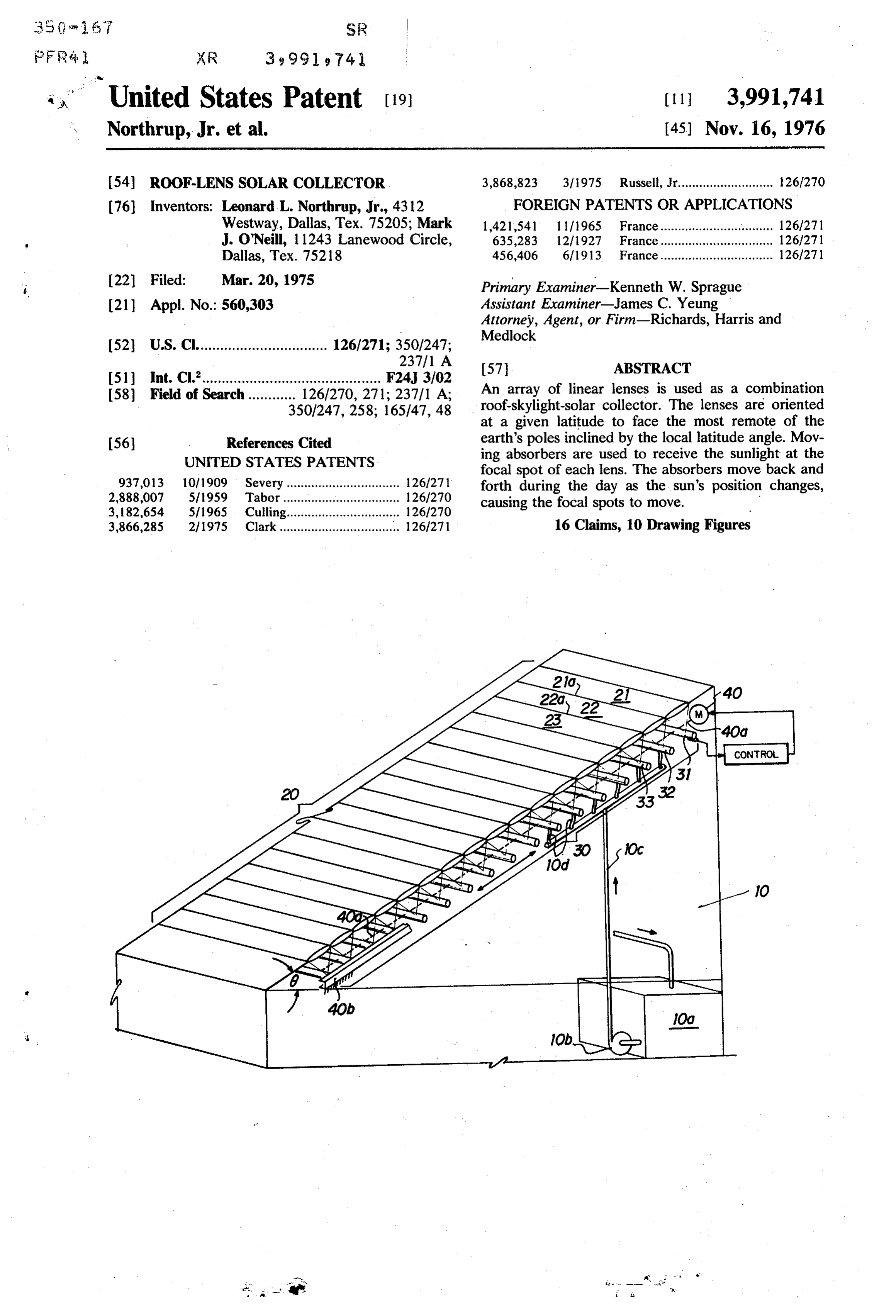
Page 1 — bibliographic record
United States Patent (19)
Northrup, Jr. et al.
(54) ROOF-LENS SOLAR COLLECTOR 3,868,823 3/1975 Russell, Jr........................... 26/270 76) inventors: Leonard L. Northrup, Jr., 4312 FOREIGN PATENTS ORAPPLICATIONS Westway, Dallas, Tex. 75205; Mark 1,421,541 l l (1965 France....................... . . . . . . . . . 126/271 J. O'Neill, 1 1243 Lanewood Circle, 635,283 12/1927 France................................ 126/271 Dallas, Tex. 75218 456,406 6/1913. France................................ 126/271 (22 Filed: Mar. 20, 1975 Primary Examiner-Kenneth W. Sprague (21) Appl. No.: 560,303 Assistant Examiner-James C. Yeung Attorney, Agent, or Firm-Richards, Harris and
Medlock 52 U.S. Cl................................. 126/271; 350/247;
(51) Int. Cl”............................................. F24, 3/02 58 Field of Search ............ 126/270, 271; 237/1 A; An array of linear lenses is used as a combination 350/247, 258; 165147, 48 roof-skylight-solar collector. The lenses are oriented at a given latitude to face the most remote of the 56) References Cited earth's poles inclined by the local latitude angle. Mov UNITED STATES PATENTS ing absorbers are used to receive the sunlight at the focal spot of each lens. The absorbers move back and 937,013 10/1909 Severy ................................ 126/27 forth during the day as the sun's position changes, 2,888,007 5/1959 Tabor................................. 126/270 causing the focal spots to move. 3,182,654 5/1965 Culling................................ 126/270 3,866,285 2/1975 Clark................................ ... 126/271 16 Claims, 10 Drawing Figures
Page 2
Drawing sheet — no readable text.
Page 3
Drawing sheet — no readable text.
Page 4
a 3,991,741
below the panel to receive light concentrated by the
ROOF-LENS SOLAR COLLECTOR lenses onto parallel lines within the structure with means responsive to daily changes in the sun's eleva
This invention relates to conversion of solar energy, tion angle relative to the lenses to maintain the ele and more particularly to a roof-lens solar collector ments of the array at all times at the focus of the sun's which in a preferred embodiment also provides for rays by the lenses thereby to provide heat input which internal lighting of a building on which the lens system is captured and at the same time providing light input forms at least a portion of the roof, to the building.
Utilization of solar energy has been the object of 10 The novel features believed characteristic of the investigation and development from the earliest of invention are set forth in the appended claims. The times. Applications wherein solar energy displaces cur invention itself, however, as well as further objects and rent use of fossil fuels becomes a more significant ob advantages thereof, will best be understood by refer jective as the supply of fossil fuel diminishes and as ence to the following detailed description of an illustra industrial and domestic needs for energy increase. 15 tive embodiment taken in conjunction with the accom Heretofore there have been many structures devised panying drawings, in which:
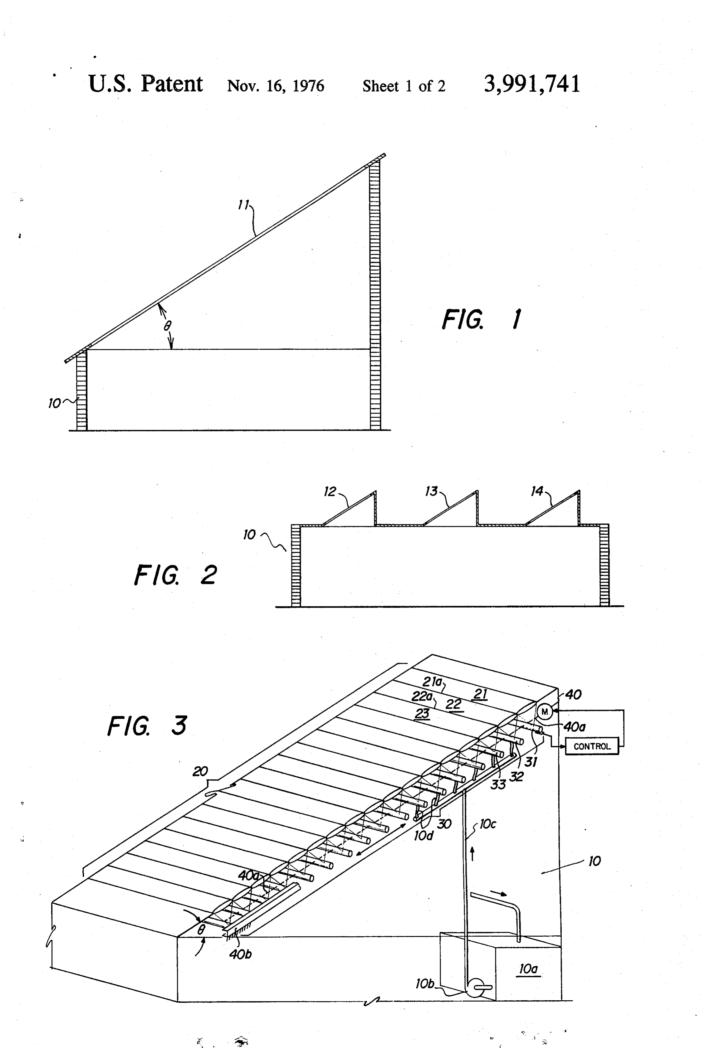
and many systems proposed for making solar energy FIG. 1 illustrates a building in which an entire roof usable in economically competitive form for industries structure is formed of a roof-lens system for collecting and homes. Solar energy capture and utilization and solar energy;
various forms of storage systems have been proposed. 20 FIG. 2 illustrates a modified form of building roof In prior application Ser. No. 523,220, filed Nov. 13, structure embodying the invention;
1974 for SOLAR ENERGY COLLECTOR, aban FIG. 3 is an isometric view partially in section illus doned, a system is disclosed employing a Fresnel lens trating the structure utilized in the systems of FIGS. 1 mounted in such a manner as to track the sun's path and 2;
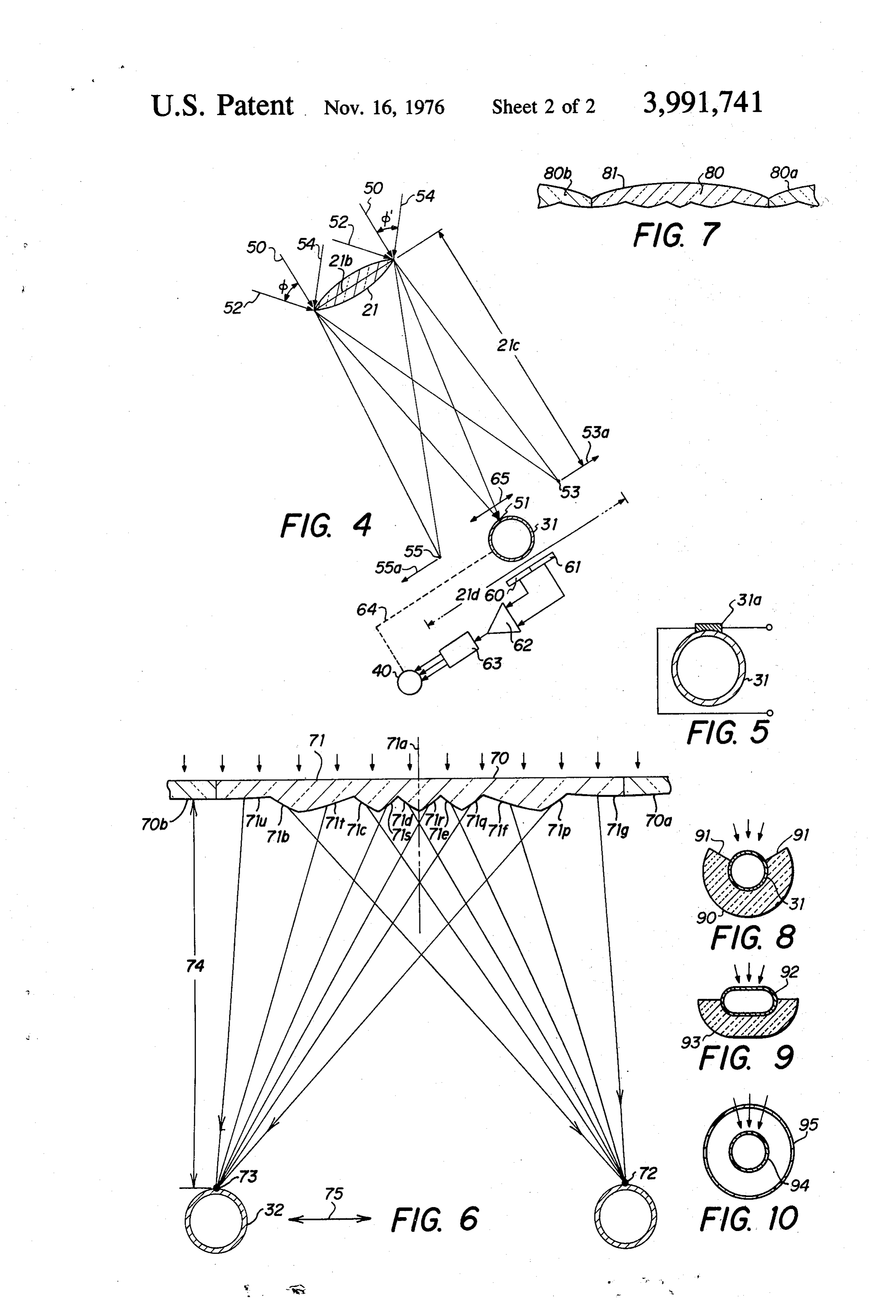
across the sky while focusing at all times the sun's rays 25 FIG. 4 diagrammatically illustrates variations in the by means of the lens onto a heat absorbent element. position of the focus of light rays impinging the lens The relatively high efficiency of such a system has from various angles as characteristically encountered made possible the utilization of solar energy for many during operation in the environments of FIGS. 1 and 2; purposes not heretofore accomplished even though FIG. 5 illustrates use of a photo voltaic cell as a solar many systems having prospects of success have been 30 energy absorber;
disclosed in the literature. FIG. 6 illustrates a modified form of cylindrical lens; The present invention is directed to a system in which FIG. 7 illustrates another embodiment of the lens of a surface portion of a structure such as a building is FIG. 6;
formed by a panel comprising an array of lenses. The FIG. 8 illustrates a sectional view of a collector of panel preferably is tilted at an angle corresponding to preferred configuration;
the latitude of the location of the structure as to receive 35 FIG. 9 illustrates a modification of the collector of the sun's rays axially at equinox. The panel is formed by FIG. 8; and a plurality of cylindrical lenses whose horizontal axes FIG. 10 illustrates a further modification of the col extend east-west. Identical lenses refract incident radi lector of FIG. 8.
ation onto a line at the focal point of each lens. An 40 Referring now to the drawings, FIG. 1 illustrates a building 10 to which the present invention is used. The array of linear heat absorbers, at least one absorber for roof each lens, is mounted within the structure below the structure 11 is tilted at an angle corresponding to lens array at the focal points of the lenses. Thus, one local latitude. In accordance with the present inven element is at the focal point for each lens. The array of tion, the roof 11 comprises in whole or at least in part absorbers are mounted for movement on a daily basis one or more panels of cylindrical lenses the structure to compensate for variation in the sun's elevation angle 45 and configuration of which will be described herein. relative to the lens. By this means, the energy from the The lenses are longitudinally horizontal extending in sun's rays concentrated onto the absorbers may be the east-west direction. The lenses serve to focus inci utilized by means of heat transfer mechanisms for utili wheredent sun's rays onto parallel lines inside the building the energy is then captured. So far as not cap zation in any of the various ways heretofore suggested. SO tured, light
In a more specific aspect, the invention comprises an passing through the lens system is utilized to elongated generally cylindrical lens to concentrate form interior illumination of building 10. parallel incident rays of light onto a focal line with . ingInaFIG. 1 the entire roof 11 is illustrated as compris single slope and may be totally or at least in part means fixedly mounting the lens with its lateral axis tilted to local latitudes and its longitudinal axis in an 55 formed of the cylindrical lens panels embodied in the east-west direction. An elongated linear heat absorbent present invention.
element is positioned below the lens at its focal dis In FIG. 2 building 10 has a horizontal roof structure tance. Control means responsive to variation in the with a plurality of tilted lens sections 12, 13 and 14 elevation angle of the sun relative to the lens in its tions mounted in structure like skylights. Each of the sec daytime travel varies the north-south position of the 60 12-14 comprises panel structures of cylindrical element to maintain it at the line along which the lens lenses to bring the incident sun's rays to linear focus focuses the incident parallel rays. lines.
In a further aspect, the invention comprises a build FIG. 3 is an illustration of a portion of one panel. ing having as a roof structure a light transmitting panel Panel 20 comprises a plurality of lenses which are inte facing south in northern hemisphere, north in southern gral one with another to form a weathertight body. For hemisphere and inclined at an angle corresponding to 65 example, lenses 21 and 22 are joined together or are local latitude and formed of a plurality of side-by-side common at the boundary 21a. Lenses 22 and 23 join at generally cylindrical lenses whose axes extend east boundary 22a. The longitudinal axes of the lenses west. The heat absorbing array of elements is mounted 21-23 are horizontal and extend in east-west direction.
Page 5
The entire panel 20 is tilted at an angle 6 preferably Elements of array 30, FIG. 3, are hollow tubes such corresponding with the local latitude at which the as tube 31, FIG. 4. A heat transfer liquid flows through building 10 is located. the tube for exchange of energy between array 30 and By way of example, the individual lenses such as lens a utilization system. As shown, a heat utilization reser 21 may have a major axis of the order of 6 inches in voir 10a is connected to receive flow of liquid from length and a minor axis of about 3 inch. Panels formed array 30. Pump 10b forces fluid through line 10c and of such lenses may be of the order of 5 feet wide and 10 manifold 10d to supply all the tubes of array 30. Reser feet long. It will be apparent, however, that there is no voir 10a may be a water heater, for example. necessary limitation on the lens size or the panel width In accordance with the invention, a control system is or length other than the physical parametric consider O provided for the actuator 40 to control the north-south ations generally applicable to use of structures employ position of the array 30. The control system may be of ing glass panels. the form diagrammatically illustrated in FIG. 4. A pair Further in accordance with the present invention, an of light sensors 60 and 61 are mounted beneath the array 30 of solar energy absorbers is provided. Array tube 21. The sensor outputs are then applied to a differ 30 comprises longitudinal tubes such as the tubes 31, 5 ential amplifier 62 whose output is applied by way of a 32 and 33. Tube 31 is mounted in a suitable support power amplifier 63 to operate actuator 40 which is a system, not shown, as to be movable under the control differential actuator having a mechanical output cou of an actuator 40 so that absorbers 31, 32 and 33 will pled by way of linkage 64 to the element 31 so that the always be positioned at the point at which the sun's rays element 31 along with the other elements in the array incident upon the lenses 21, 22 and 23, respectively, 20 30 may be moved in accordance with arrow 65. The are focused. This concentration of the sun's rays thus output from sensors 60 and 61 will at all times be provides for an efficient collection of solar energy by nulled, indicating that the sun's rays are refracted to a tubes 31-33 as concentrated by lenses 21-23. line positioned centrally on the upper surface of the As above noted, the array 20 is tilted at an angle 8 of element 31.
approximately the latitude angle at which the building 25 The principles of feedback control systems, in gen is located. The angle may be varied, however, for any eral, are well known and will not further be described. given latitude and the control of an actuator 40 ad In the present system, the control system functions to justed to accommodate the differences thus involved. maintain the elements of the array 30 always to receive Actuator 40 is coupled to array 30 by way of an inter the sun's rays as focused by the lens elements of the connecting linkage 4.0a which ties the members of 30 array 20.
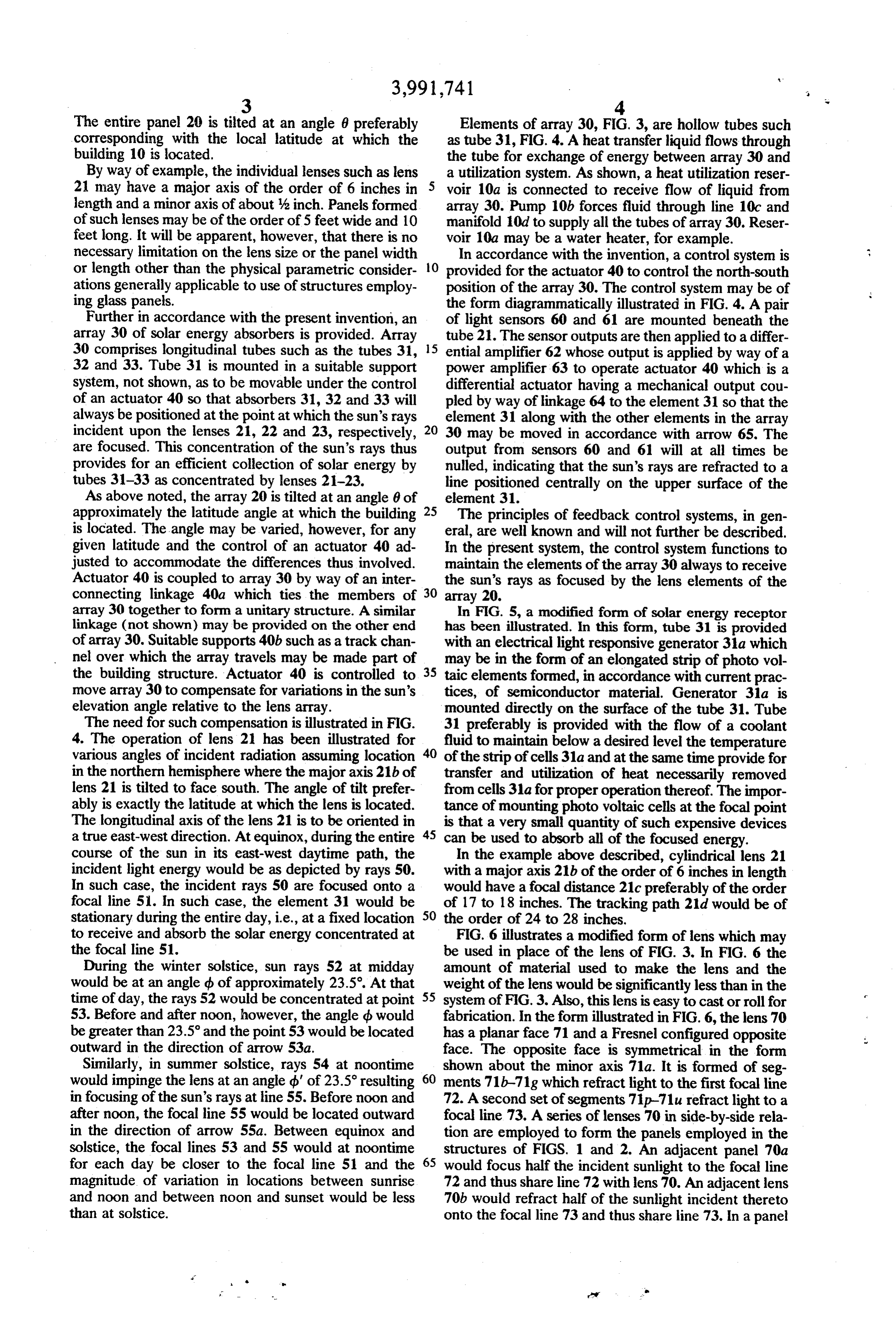
array 30 together to form a unitary structure. A similar In FIG. 5, a modified form of solar energy receptor linkage (not shown) may be provided on the other end has been illustrated. In this form, tube 31 is provided of array 30. Suitable supports 40b such as a track chan with an electrical light responsive generator 31a which nel over which the array travels may be made part of may be in the form of an elongated strip of photo vol the building structure. Actuator 40 is controlled to 35 taic elements formed, in accordance with current prac move array 30 to compensate for variations in the sun's tices, of semiconductor material. Generator 31a is elevation angle relative to the lens array. mounted directly on the surface of the tube 31. Tube The need for such compensation is illustrated in FIG. 31 preferably is provided with the flow of a coolant 4. The operation of lens 21 has been illustrated for 40 fluid to maintain below a desired level the temperature various angles of incident radiation assuming location of the strip of cells31a and at the same time provide for in the northern hemisphere where the major axis 21b of transfer and utilization of heat necessarily removed lens 21 is tilted to face south. The angle of tilt prefer from cells 31a for proper operation thereof. The impor ably is exactly the latitude at which the lens is located. tance of mounting photo voltaic cells at the focal point The longitudinal axis of the lens 21 is to be oriented in is that a very small quantity of such expensive devices a true east-west direction. At equinox, during the entire 45 can be used to absorb all of the focused energy. course of the sun in its east-west daytime path, the In the example above described, cylindrical lens 21 incident light energy would be as depicted by rays 50. with a major axis 21b of the order of 6 inches in length In such case, the incident rays 50 are focused onto a would have a focal distance 21c preferably of the order focal line 5. In such case, the element 31 would be of 17 to 18 inches. The tracking path 21d would be of stationary during the entire day, i.e., at a fixed location 50 the order of 24 to 28 inches. to receive and absorb the solar energy concentrated at FIG. 6 illustrates a modified form of lens which may the focal line 51. be used in place of the lens of FIG. 3. In FIG. 6 the During the winter solstice, sun rays 52 at midday amount of material used to make the lens and the would be at an angle d of approximately 23.5. At that weight of the lens would be significantly less than in the time of day, the rays 52 would be concentrated at point 55 system of FIG. 3. Also, this lens is easy to cast or roll for 53. Before and after noon, however, the angle b would fabrication. In the form illustrated in FIG. 6, the lens 70 be greater than 23.5° and the point 53 would be located has a planar face 71 and a Fresnel configured opposite outward in the direction of arrow 53a. face. The opposite face is symmetrical in the form Similarly, in summer solstice, rays 54 at noontime shown about the minor axis 71a. It is formed of seg would impinge the lens at an angle d' of 23.5° resulting 60 ments 71b-71g which refract light to the first focal line in focusing of the sun's rays at line 55. Before noon and 72. A second set of segments 71p–71u refract light to a after noon, the focal line 55 would be located outward focal line 73. A series of lenses 70 in side-by-side rela in the direction of arrow 55a. Between equinox and tion are employed to form the panels employed in the solstice, the focal lines 53 and 55 would at noontime structures of FIGS. 1 and 2. An adjacent panel 70a for each day be closer to the focal line 51 and the 65 would focus half the incident sunlight to the focal line magnitude of variation in locations between sunrise 72 and thus share line 72 with lens 70. An adjacent lens and noon and between noon and sunset would be less 70b would refract half of the sunlight incident thereto than at solstice. onto the focal line 73 and thus share line 73. In a panel
Page 6
3,991,741 i.
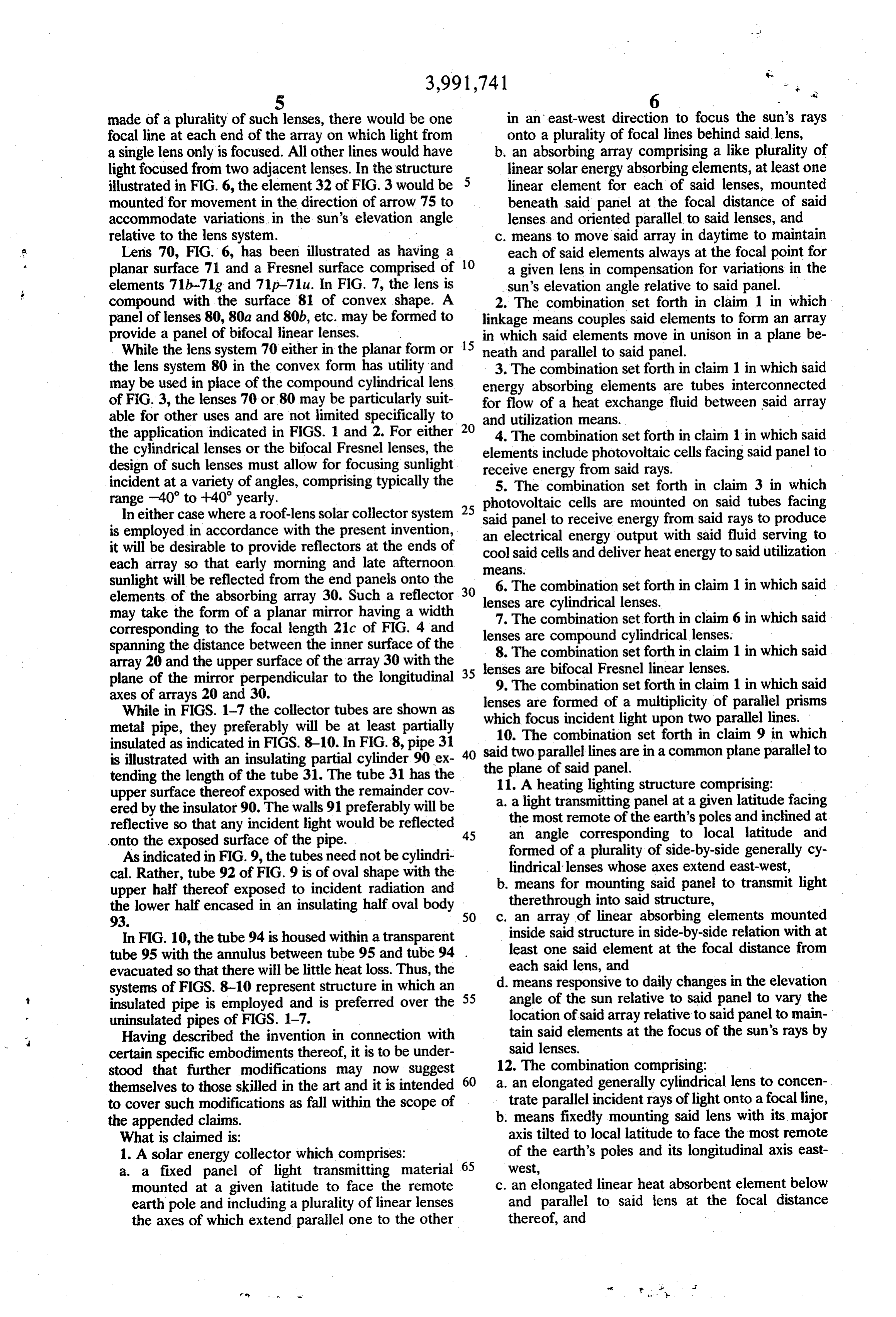
5 6 s made of a plurality of such lenses, there would be one in an east-west direction to focus the sun's rays focal line at each end of the array on which light from onto a plurality of focal lines behind said lens, a single lens only is focused. All other lines would have b. an absorbing array comprising a like plurality of light focused from two adjacent lenses. In the structure linear solar energy absorbing elements, at least one illustrated in FIG. 6, the element 32 of FIG. 3 would be linear element for each of said lenses, mounted mounted for movement in the direction of arrow 75 to beneath said panel at the focal distance of said accommodate variations, in the sun's elevation angle lenses and oriented parallel to said lenses, and relative to the lens system. c. means to move said array in daytime to maintain Lens 70, FIG. 6, has been illustrated as having a each of said elements always at the focal point for planar surface 71 and a Fresnel surface comprised of 10 a given lens in compensation for variations in the elements 71b-71g and 71p-71 u. In FIG. 7, the lens is sun's elevation angle relative to said panel. compound with the surface 81 of convex shape. A 2. The combination set forth in claim 1 in which panel of lenses 80, 80a and 80b, etc. may be formed to linkage means couples said elements to form an array provide a panel of bifocal linear lenses. in which said elements move in unison in a plane be While the lens system 70 either in the planar form or 15 neath and parallel to said panel.
the lens system 80 in the convex form has utility and 3. The combination set forth in claim 1 in which said may be used in place of the compound cylindrical lens energy absorbing elements are tubes interconnected of FiG. 3, the lenses 70 or 80 may be particularly suit for flow of a heat exchange fluid between said array able for other uses and are not limited specifically to 20 and utilization means.
the application indicated in FIGS. 1 and 2. For either 4. The combination set forth in claim 1 in which said the cylindrical lenses or the bifocal Fresnel lenses, the elements include photovoltaic cells facing said panel to design of such lenses must allow for focusing sunlight receive energy from said rays. - incident at a variety of angles, comprising typically the 5. The combination set forth in claim 3 in which range -40° to +40 yearly. photovoltaic cells are mounted on said tubes facing In either case where a roof-lens solar collector system 25 said panel to receive energy from said rays to produce is employed in accordance with the present invention, an electrical energy output with said fluid serving to it will be desirable to provide reflectors at the ends of each array so that early morning and late afternoon cool eaS.
said cells and deliver heatenergy to said utilization sunlight will be reflected from the end panels onto the 30 6. The combination set forth in claim 1 in which said elements of the absorbing array 30. Such a reflector may take the form of a planar mirror having a width lenses are cylindrical lenses. 7. The combination set forth in claim 6 in which said corresponding to the focal length 21c of FIG. 4 and lenses are compound cylindrical lenses.
spanning the distance between the inner surface of the 8. The combination set forth in claim 1 in which said array 20 and the upper surface of the array 30 with the 35 lenses are bifocal Fresnel linear lenses. plane of the mirror perpendicular to the longitudinal 9. The combination set forth in claim 1 in which said axes of arrays 20 and 30. lenses are formed of a multiplicity of parallel prisms While in FIGS. 1-7 the collector tubes are shown as metal pipe, they preferably will be at least partially which focus incident light upon two parallel lines. 10. The combination set forth in claim 9 in which insulated as indicated in FIGS. 8-10. In FIG. 8, pipe 31 40 said two parallel lines are in a common plane parallel to is illustrated with an insulating partial cylinder 90 ex the plane of said panel.
tending the length of the tube 31. The tube 31 has the 11. A heating lighting structure comprising: upper surface thereof exposed with the remainder cov a. a light transmitting panel at a given latitude facing ered by the insulator 90. The walls 91 preferably will be reflective so that any incident light would be reflected 45 an mostthe remote of the earth's poles and inclined at angle corresponding to local latitude and onto the exposed surface of the pipe. formed of a plurality of side-by-side generally cy As indicated in FIG.9, the tubes need not be cylindri lindrical lenses whose axes extend east-west, cal. Rather, tube 92 of FIG. 9 is of oval shape with the b. means for mounting said panel to transmit light upper half thereof exposed to incident radiation and the lower half encased in an insulating half oval body SO c. therethrough an array of into said structure, linear absorbing elements mounted
In FIG. 10, the tube 94 is housed within a transparent inside said structure in side-by-side relation with at tube 95 with the annulus between tube 95 and tube 94 . least one said element at the focal distance from evacuated so that there will be little heat loss. Thus, the each said lens, and systems of FIGS. 8-10 represent structure in which an 55 d. means responsive to daily changes in the elevation insulated pipe is employed and is preferred over the angle of the sun relative to said panel to vary the uninsulated pipes of FIGS. 1-7. location of said array relative to said panel to main Having described the invention in connection with tain said elements at the focus of the sun's rays by certain specific embodiments thereof, it is to be under said lenses.
stood that further modifications may now suggest 12. The combination comprising: themselves to those skilled in the art and it is intended 60 a. an elongated generally cylindrical lens to concen to cover such modifications as fall within the scope of trate parallel incident rays of light onto a focal line, the appended claims. b. means fixedly mounting said lens with its major What is claimed is: axis tilted to local latitude to face the most remote 1. A solar energy collector which comprises: of the earth's poles and its longitudinal axis east a. a fixed panel of light transmitting material 65 west, mounted at a given latitude to face the remote c. an elongated linear heat absorbent element below earth pole and including a plurality of linear lenses and parallel to said lens at the focal distance the axes of which extend parallel one to the other thereof, and
Page 7
ag 7 8 d. means responsive to variations in the elevation 16. In the conversion of solar energy, the method angle of the sun relative to said cylindrical lens in comprising: O w its daytime travel to vary the north-south position a. refracting, in an east-west oriented layer tilted to of said element to maintain it at the point of focus local latitude to face the most remote of the earth's of the sun's rays. 5 poles, incident solar radiation to focus said radia 13. A bifocal linear lens comprising a multiplicity of tion to a plurality of east-west lines common to a parallel prisms which focus incident sunlight upon two focal plane beneath said refracting plane, parallel lines lying in a common plane beneath said b. positioning interceptors for said rays along said lines to absorb heat from said rays at one time of lens. O day, and 14. The combination set forth in claim 13 in which c. moving said interceptors to compensate for said lens has a planar face subject to incident radiation. changes in north-south positions of said lines due to 15. The combination set forth in claim 13 in which variation in the elevation angle of the sun relative said lens has a convex face subject to incident radia- to said refracting layer. tion. 15 k . . . . .
Provenance
- Collection
- Cited prior art
- Original PDF
- patentimages.storage.googleapis.com →
- Filed
- 1975-03-20
- Pages
- 7
- Method
- pdftotext (the PDF's own text layer) + pdftoppm 300dpi page scans
- Source
- Google Patents bibliographic record
- Granted
- 1976-11-16
- Inventors
- Leonard L. Northrup, Jr.; Mark J. O'Neill
- Transcribed from
- patentimages.storage.googleapis.com →