patent · US3738734
Optical fluid lens construction
12 June 1973
Page 1 — bibliographic record
OR 3738 (34 -
United States P 3,738,734 Tait et al. June 12, 1973 (54) OPTICAL FLUID LENS CONSTRUCTION Primary Examiner-John K. Corbin 76 Inventors: Stuart S. Tait, 3 Marydons Crescent, Attorney-Peter W. McBurney and Donald F. Sim Agincourt, Ontario; Thomas T.
Reider, 47 Brahms Avenue, 57 ABSTRACT
Willowdale, Ontario, both of Canada
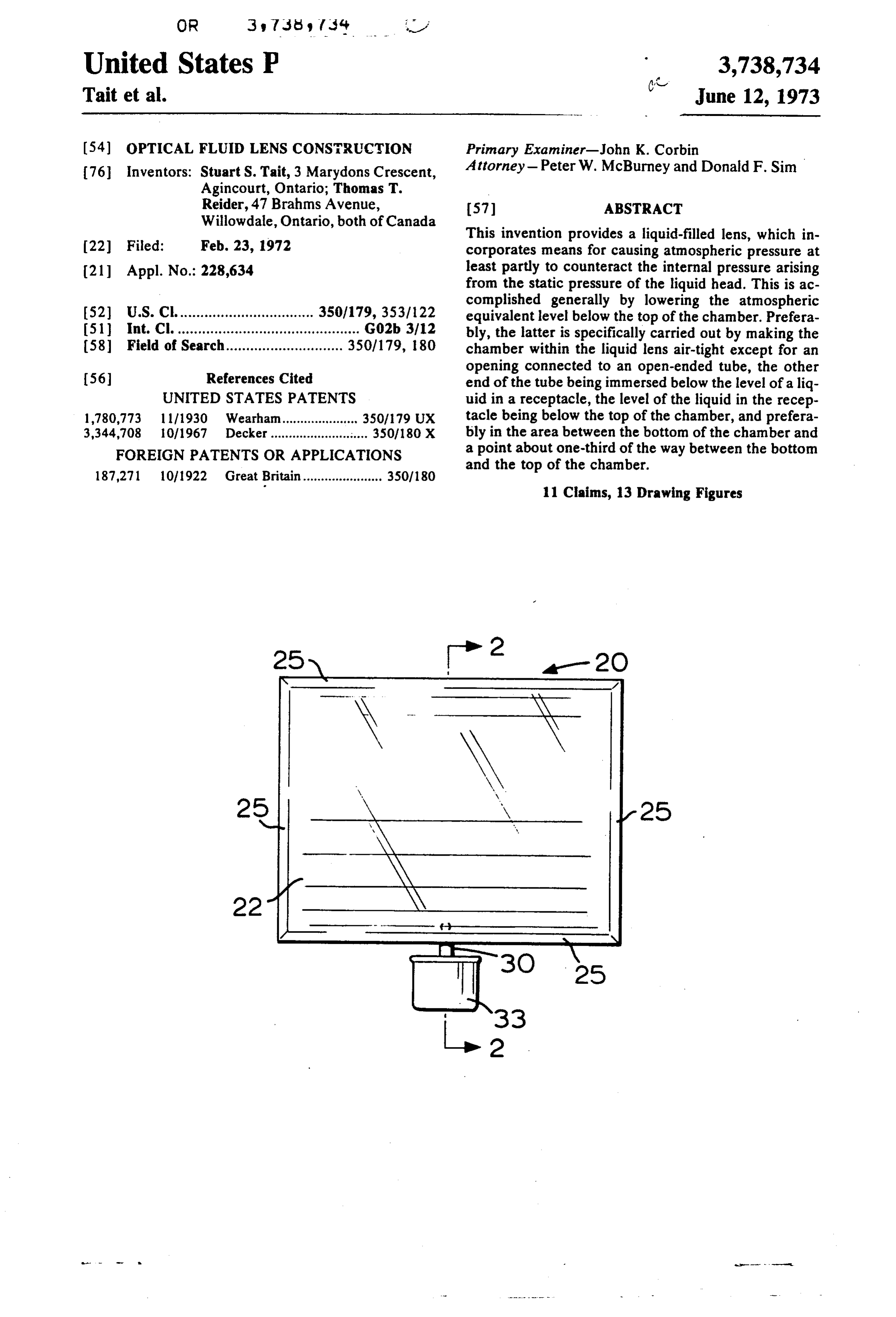
This invention provides a liquid-filled lens, which in 22 Filed: Feb. 23, 1972 corporates means for causing atmospheric pressure at (21) Appl. No.: 228,634 least partly to counteract the internal pressure arising from the static pressure of the liquid head. This is ac complished generally by lowering the atmospheric (52) U.S. C. ................................. 350/179, 353/122 equivalent level below the top of the chamber. Prefera (51) int. Cl. ............................................. G02b 3/12 bly, the latter is specifically carried out by making the (58) Field of Search............................. 350/179, 180 chamber within the liquid lens air-tight except for an
opening connected to an open-ended tube, the other end of the tube being immersed below the level of a liq
UNITED STATES PATENTS uid in a receptacle, the level of the liquid in the recep 1,780,773 1 1/1930 Wearham..................... 350/179 UX tacle being below the top of the chamber, and prefera 3,344,708 10/1967 Decker........ ............ 350/180 X bly in the area between the bottom of the chamber and FOREIGN PATENTS OR APPLICATIONS a point about one-third of the way between the bottom 187,271 10/1922 Great Britain - - - - - - - - - - - - - O - O - 350/180 and the top of the chamber.
11 Claims, 13 Drawing Figures
Page 2
Drawing sheet — no readable text.
Page 3
Drawing sheet — no readable text.
Page 4
OPTICAL FLUD LENS CONSTRUCTION and removed with ease and efficiency, it is not difficult to visualize a great multiplicity of uses for such a lens.
This invention relates generally to lens-like optical Assuming that the lens is of the magnifying type (dou devices, for magnifying or diminishing the apparent ble-convex, or plano-convex), it would be very useful size of an object. More particularly, this invention has in school and university lecture rooms, permitting the to do with the construction of a lens-like optical device teacher or professor to show prototypes, models and which permits the manufacture of very large size lenses specimens to a large audience in true three with diameters up to 8 or 10 feet. dimensional depth and at increased size. It would also
GENERAL BACKGROUND OF THE INVENTION O
be extremely useful in merchandising stores, particu
Optical lenses are very well known and have been used larly in display windows which up to now have been manufactured and used commercially for centuries. publiconly is for large-size items, due to the fact that the usually kept from 4 to 8 feet away from the
Early lenses were always made of glass, and required merchandise on display. With a large-diameter lens in laborious grinding techniques in order to provide them the window, it would be possible to display a whole tray with properly curved, optically smooth refraction sur of jewelry, smaller items like cameras,
faces. Because of the difficulties of the grinding tech forth. The application of a large-diameterpens, and so niques, the cost of manufacture of a ground-glass lens television industry is obvious. By purchasing atolesslens the varies as the third or fourth power of its diameter, thus making lenses over one foot in diameter prohibitively expensive small-tube portable television set and a large-diameter lens, the customer could use the televi costly for other than telescopic applications.
More recently, the smaller lenses have been manu sion set as is for smaller rooms in which close-up view factured from clear, colorless plastic material, usually ing is enforced, and could magnify the television tube by casting techniques utilizing molds with optically through the lens for viewing in larger rooms where the smooth surfaces. In solidifying within the mold, the viewers are seated further away.
plastic picks up the optically smooth characteristics for 25 The point of departure for the present invention is a its refraction surfaces. Although this casting technique concept that has been known for over 100 years. It is is relatively inexpensive as compared with ground-glass to provide a chamber defined in part by two juxtaposed lenses, plastic, too, has certain characteristics which transparent walls configured to each other as the sur limit the size of the plastic lenses. These limitations 30 faces of a lens. The chamber is capable of holding a liq have to do with the solidification of plastic within a uid such as water, and thus the interfaces between the mold. As plastic solidifies from the liquid to the solid water and the transparent walls function as the refrac state, it invariably undergoes contraction. Also, plastic tion surfaces of a lens. This prior art concept is fine in cannot generally be cast in thicknesses greater than principle, but has certain serious disadvantages which about two inches, because the plastic in the center of will now be described.
the thicker portions of the item will solidify last, caus 35 DISADVANTAGES OF THE PRIOR ART ing the greatest amount of shrinkage at those thicker portions with the resultant distortion and stress in the The use of a liquid within an upright chamber defined item. Distortion, of course, must be absolutely elimi between two substantially vertical walls leads inevitably nated in the manufacture of a lens, and this is why it has not been possible heretofore to cast a large-diameter 40 to certain problems relating to the static head of the liq uid. For example, if a water-filled lens had a vertical lens of appreciable magnifying power. To give an ex height of 3 feet, the static pressure at the bottom of the ample, a plastic double-convex lens of 2 foot diameter column of liquid would be about 1.3 psig. This would would require a center thickness of from 4 to 6 inches result in a total outward pressure on each wall, taken in order for its focal length to be reasonably short. (The exact focal length would depend, of course, upon the 45 over inch.
its full height, of about 23.4 pounds per lateral
Hence, if the lens were of square configuration, index of refraction of the plastic being used.) It would 36 inches on a side, the total outward pressure against be extremely difficult, however, to cast a lens of this type from plastic by normal molding techniques, be each wall would be on the order of 840 pounds. This force would have to be contained at the edges of each cause the center portion of the lens would be distorted 50 wall, so greatly that the lens would be useless for magnifica alongwith the the greatest portion of the load being borne bottom edge. As the head increases, the total tion purposes.
Thus, the manufacture of large-diameter lenses from load on each wall per lateral inch goes up also, the load ground-glass has the disadvantage of prohibitive ex varying as the square of the height. Thus, by doubling pense, while the use of plastic has the limitation of un the height of the column of water, the load on each wall avoidable distortion which present-day techniques 55 per lateral inch is quadrupled. If the lens were rectan have not been able to eliminate. gular, and the same proportion of height to width were Even if it were possible to construct an optically true used for both the smaller and the larger lens, then the lens of, say, three foot diameter from either glass or width of the lens would also double, and this would plastic, it is obvious that the sheer weight of the mate 60 mean that the total load upon the lens would vary as the rial in such a lens (particularly if it were made of glass) cube of the height. Thus, for a square lens 6 feet in would make it totally unsuited for applications requir width and height filled with water, the total outward ing the lens to be put in place and removed with ease load on each wall would be around 6,700 pounds, or and facility. Furthermore, the additional weight of better than 3 tons.
large-diameter lenses of this type would increase the This tremendous outward force against the transpar costs of shipping and handling. ent walls of a vertically oriented lens would appear to If it were possible to produce a low-cost, lightweight, stand in the way of manufacturing a water-filled lens large-diameter magnifying lens which could be set up with a vertical dimension greater than 3 or 4 feet.
Page 5
OBJECTS OF THIS INVENTION FIGS. 10 and 11 are force diagrams relating to the second embodiment of this invention;
Accordingly, it is an object of this invention to pro FIG. 12 is a sectional view of a portion of FIG. 9, to vide a liquid-filled lens construction in which the out a larger scale; and ward pressure exerted against the transparent side walls FIG. 13 is an example of the use of this invention in by the liquid head is counteracted at least in part by at a projection context.
mospheric pressure acting inwardly.
An object of a preferred embodiment of this inven DETAILED DESCRIPTION OF THE DRAWINGS: tion is to provide a combination of lens, screen and pro Referring to FIGS. 1 and 2, a lens 20 includes a first jector which permits the showing of slides and movie 10 transparent wall 22 and a second transparent wall 24. film to an audience without requiring the room to be In the embodiment shown, each of the transparent darkened. walls 22 and 24 is of uniform thickness, although this is not essential to the invention. What is essential is that
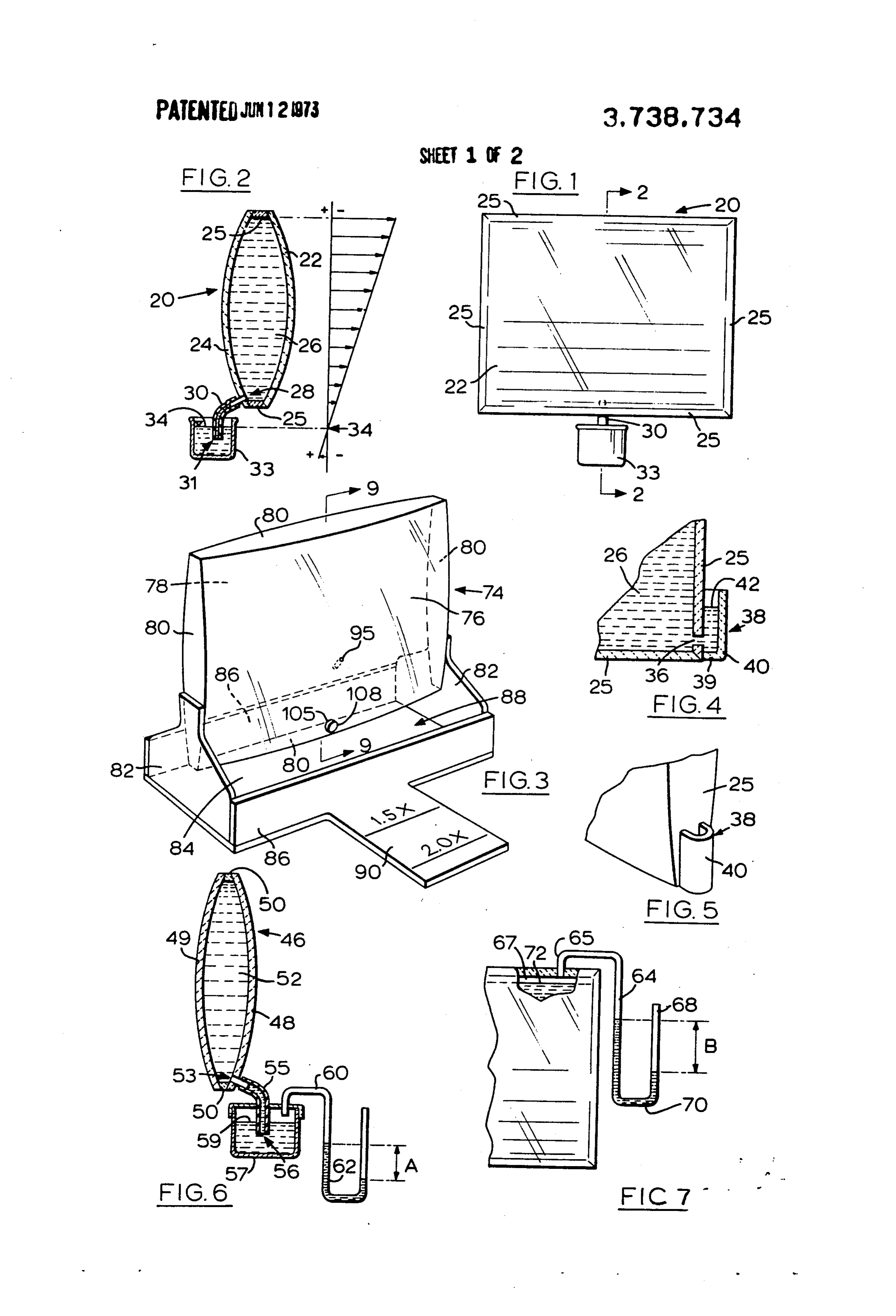
GENERAL DESCRIPTION OF THE INVENTION the inner and outer surfaces of each wall 22 and 24 be Accordingly, this invention provides an optical de 15 optically smooth, and that at least the inner surfaces of vice comprising two juxtaposed transparent walls defin the walls 22 and 24 be configured to each other as the ing between them a chamber capable of holding a liq surfaces of a lens. In the embodiment shown, the lens uid, each wall having optically smooth inner and outer is a double-convex lens, and for this reason each of the surfaces, the inner surfaces of the walls being config walls 22 and 24 is outwardly convex. Generally speak ured to each other as the surfaces of a lens, the optical ing, where a transparent wall is curved, it should ap device including means for decreasing the absolute proximate as closely as possible a spherical curvature. pressure at the top of the chamber, thereby lowering However, the lens could very easily be constructed as the atmospheric equivalent level below the top of the a plano-convex lens shown in FIG. 8a, a plano-concave chamber. Preferably, this means for decreasing pres lens as shown in FIG. 8b, a concavo-convex lens as sure functions as a result of the pull of gravity. One 25 shown in FIG. 8c, and a double-concave lens as shown construction for achieving this lowering of pressure in in FIG. 8d. The first embodiment of this invention is volves providing aperture means for communicating considered to include all of the shapes illustrated in the chamber with a location within a receptacle, which FIGS. 2 and 8, these being merely configurational vari location is adapted to be submerged when the recepta ants of the first embodiment.
cle contains a given amount of liquid. The chamber is 30 Preferably, the transparent walls are colorless al adapted to be sealed, apart from the aperture means, though tinted walls would also fall within this invention. and the liquid-air interface in the receptacle (which de The preferred material for the construction of the fines the atmospheric equivalent level for the chamber) transparent walls 22 and 24 is an acrylic material gen lies below the top of the chamber. By this provision, the 35 erally known as "Plexiblas' (Reg. T.M.), although nu atmospheric pressure is caused to press inwardly merous other transparent rigid materials are available. against the walls of the water-filled lens to counteract This invention also encompasses the manufacture of the pressure that is exerted by the head of water within the transparent walls 22 and 24 from glass. the lens. If the atmospheric equivalent level is below In FIGS. 1 and 2, although the lens is of the double the mid-plane of the walls, there results a net inward 40 convex type, the lens has been "trimmed' to a rectan pressure against the walls. In the embodiment where gular shape. Thus, the lens 20 shown in FIGS. 1 and 2 the walls are convex outwardly (a double-convex lens), comprises, in addition to the first and second transpar a net inward pressure is effectively resisted by the con ent walls 22 and 24, four double-tapered edge members vex shape, for the same reason that it is so difficult to 25 which span between the adjacent edges of the trans
parent walls 22 and 24.
GENERAL DESCRIPTION OF THE DRAWINGS As mentioned above, when the vertical dimension of a vertically oriented liquid-filled lens is large, the load
Five embodiments of this invention are shown in the per lateral inch of transparent wall goes up as the accompanying drawings, in which like numerals denote square of the height of the column of liquid, while the like parts throughout the several views, and in which: 50 total load on a transparent wall (whose width dimen FIG. 1 is an elevational view of the first embodiment sion increases in proportion to the height dimension) of this invention; varies as the cube of the height of the column of liquid. FIG. 2 is a vertical sectional view taken at the line Thus, doubling all dimensions of a lens multiplies by 2-2 in FIG. 1, including a pressure diagram; eight the total load on each transparent wall. In the em FIG. 3 is a perspective view of the second embodi 55 bodiment of FIGS. 1 and 2, the natural pressure of the ment of this invention; atmosphere is made to counteract the pressure of the FIG. 4 is a vertical sectional view of a portion of the static head of liquid within the liquid-filled lens, and the third embodiment of this invention; construction by which this is provided will now be de FIG. 5 is a perspective view of the embodiment illus scribed in detail.
trated in FIG. 4; The chamber 26 defined between the transparent FIG. 6 is a vertical sectional view of the fourth em 60 walls 22 and 24 is made air-tight, and the only access bodiment of this invention; to the chamber 26 is through an aperture 28 which FIG. 7 is an elevational view of a portion of a lens, communicates through a tube 30 with a location 31 showing the fifth embodiment of this invention; within a receptacle 33. The location 31 is such that it FIG. 8 is a sectional view of alternate lens-shapes; 65 is adapted to be submerged when the receptacle 33 FIG. 9 is a vertical sectional view of the second em contains a given amount of liquid. In FIG. 2, it can be bodiment of this invention, taken at the lines 9-9 in seen that the air-liquid interface 34 lies above the loca FIG. 3; tion 31.
Page 6
S 6
Because the lower end of the tube 30 is submerged Attention is now directed to FIGS. 4 and 5, in which beneath the surface of liquid in the receptacle 33, and the second embodiment is shown. In FIG. 4, one of the because the chamber 26 is air-tight except for the aper edge members 25 is provided with an aperture 36 open ture 28, no air can enter the chamber 26. Furthermore, ing directly into the interior of a receptacle 38 defined and more importantly, the static pressure over the en by a bottom wall 39, a semi-cylindrical side wall 40 and tire column of liquid beginning at the interface 34 and the edge member 25 containing the aperture 36. It will going up through the tube 30 and up to the top of the be seen that the aperture 36 opens into the interior of chamber 26 is less than atmospheric pressure, the dif the receptacle 38 at a location below the liquid-air in ference in pressure being greatest at the top and de terface 42, and this prevents air from entering the creasing linearly down to the lever 34. However, the chamber 26 through the aperture 36. In FIG. 4, the lo
pressure of the atmosphere against the outside of each cation of the liquid-air interface 42 determines the at of the transparent walls 22 and 24 is constant at around mospheric equivalent level for the second embodiment 15 psi and since the pressure within the chamber 26 is of the invention. It will be noted that a small portion of at all points less than atmospheric pressure, the net the chamber 26 lies below the liquid-air interface 42, pressure against each transparent wall 22 and 24 must 15 and this will mean that the pressure in that portion will be inwardly. Thus, the seals between the edge member gradually increase in the downward direction. How 25 and the transparent walls 22 and 24 are urged to ever, if the liquid-air interface 42 is maintained as close gether rather than apart. as possible to the bottom of the chamber 26, the net Also, should any leak develop between the edge outward pressure on the portion of the transparent member 25 and the transparent walls 22 and 24, no liq walls below the atmospheric equivalent level will be uid would leak out, but rather air would leak in. As the minimized. Also, by arranging the interface 42 to lie air leaked into the chamber 26, liquid would run out below the mid-point (vertically) of the transparent through the tube 30, and gradually fill the receptacle 33. If the receptacle 33 had sufficient capacity to ac walls, in the the greater pressure of the atmosphere inwardly upper part of the transparent walls will effec commodate all of the liquid contents of the chamber 25 tively counteract 26, or if the receptacle were in turn located within a pressure below thetheinterface slightly greater than atmospheric
larger container with that capacity, any risk of damage Attention is now directed to FIG. 6, in which the to surroundings through leakage of the liquid would be third embodiment of this invention is illustrated. In totally eliminated.
Throughout the remainder of this disclosure, and in walls 48 and 49, and four edge members 50transparent 30 FIG. 6, a lens 46 includes first and second the appended claims, the expression "atmospheric only two are visible in FIG. 6). Thus, a central(of which chamber equivalent level' will be taken to mean the level in a 52 is defined between the transparent walls 28 and 49. standing column of liquid at which the pressure of the liquid is the same as that of atmosphere. In the FIG. 2 As in the embodiment of FIG. 2, an aperture 53 com embodiment, the atmospheric equivalent level is the 35 municatesa receptacle through a tube 55 with a location 56 within 57. A liquid-gas interface 59 within the re level of the air-liquid interface 34.
While water (fresh or salt) is the preferred liquid to ceptacle 57 is located above the location 56 at the bot be utilized in the chamber 16, because of its cheapness tom end of the tube 55.
and ready availability, this invention also encompasses 40 The receptacle 57 is sealed against communication the use of other transparent liquids such as mineral oil. with the atmosphere, and an S-tube 60 opens through In certain applications, the use of other liquids has ad the upper portion of the receptacle 57, communicating vantages over the use of water, because the indices of therewith above the level of the liquid-gas interface 59. refraction of many liquids are greater than that of water The S-tube 60 contains a liquid 62, such as mercury, (1.333), and because the densities of some of these are and the liquid 62 is arranged such that there is a differ close to or less than the density of water. A higher 45 ence A in height between the two arms of the liquid, index of refraction shortens the effective focal length the higher arm being closest to the point at which the of the lens, and this provides advantages which will be S-tube opens into the receptacle 57. The lower arm of described in detail later in this disclosure. A liquid with the liquid 62 is open to the atmosphere through the lower density than that of water can be used to advan 50 other end of the S-tube 60.
tage in large lenses where a considerably volume of liq If the height A were zero, then the pressure within uid is required to fill the lens. While it is preferably that the receptacle 57 above the liquid would be the same the liquid employed be colorless as well as transparent, as the atmosphere, and the pressure profile of the vari this is obviously not essential since a certain degree of ant shown in FIG. 6 would be the same as that for the tint may be permitted, or even desired in some in embodiment of FIG. 2, with the atmospheric equivalent stances. Naturally any liquid utilized must be one which 55 level being located at the liquid-gas interface S9. does not attack the transparent walls 22 and 24 either Where, however, the distance A is greater than zero, chemically or physically. the air pressure above the liquid in the receptacle 57 Included in FIG. 2 at the right is a pressure diagram will be less than atmospheric by the pressure equivalent showing the decrease in static pressure in the tube 30 60 of the height A. If the liquid in the chamber 52 and in and in the chamber 26. The vertical line represents at the receptacle 57 is water, the atmospheric equivalent mospheric pressure (about 15 psi), and arrows to the level for the chamber 52 will be lowered to a point right and left of this line represent a decrease and in below the interface 59, the distance below being the crease, respectively, from atmospheric pressure. This same as the height A. If the liquid is mercury, then the has been indicated by plus and minus signals. The 65 height A of mercury must be converted to the equiva length of the arrows to the right in FIG. 4 can be taken lent height of a column of water (which necessitates to represent the degree of partial vacuum as compared multiplying by approximately 13.6), and the atmo with atmospheric pressure. spheric equivalent level will be found below the inter
Page 7
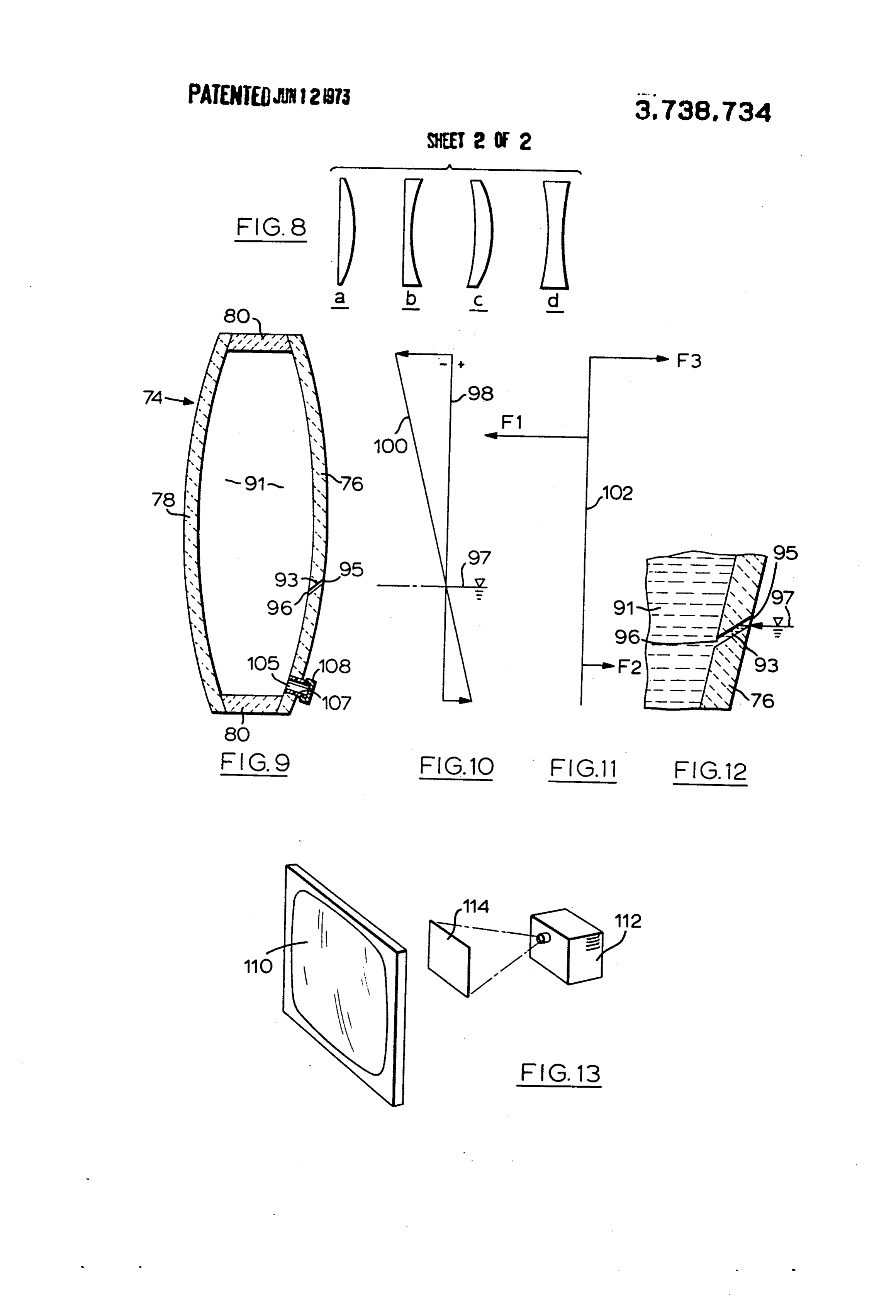
face 59 by a distance equal to the equivalent height of the line 98, the pressure is greater than atmospheric. the column of water. Where the two lines cross, the pressure inside and out The fourth embodiment of this invention is shown in side each wall 76 and 78 is the same, this being a point FIG. 7, to which attention is now directed. In FIG. 7, one third of the way between the bottom and the top an S-tube 64 has one end 55 communicating with the of the chamber 9.
upper end of a chamber 67, and has its other end 68 In FIG. 11, the triangles of pressure shown in FIG. 10 open to the atmosphere. Mercury 70 (or any other suit are resolved into forces acting at single points. The cen able liquid) is contained in the lower portion of the S ter of gravity of a triangle is located one-third of the tube 64, and the two arms of the mercury stand at dif way between the mid-point of a base and the opposite ferent heights. The difference in height, B, determines 1 O apex. In FIG. 11 the arrow marked F1 is a force vector the extent to which the pressure in the chamber 67 is representing the total force of the upper triangle in reduced below atmospheric. The height B must first be FIG. 10. The vector F1 is located one-third of the way converted to the equivalent height of a column of water between the top of the chamber 91 and the line 97. The (by multiplying the height B by approximately 13.6), vector marked F2 is located one third of the way be and then the atmospheric equivalent level will be found 5 tween the bottom of the chamber 91 and the line 97, below the liquid-gas interface 72 by a distance equal to and has the opposite sense from that of the vector F1. the water-column equivalent of the height B. As men The lengths of the vectors F1 and F2 are proportional tioned above, provided the atmospheric equivalent to the area of the two triangles they represent, and for level is located below the mid-point of the chamber 67, this reason F1 is four times as long as F2. In order to the net pressure on the transparent walls will be in exactly balance the counter-clockwise torque on the wardly. wall 76 (represented by the vertical line 102 in FIG. Attention is now directed to FIG. 3, which shows the 11), it is merely necessary to apply a force F3 at the top fifth embodiment of this invention. In FIG. 3, a rectan of the line 102, the length of the vector F3 being the gular liquid-lens 74 includes a first transparent wall 76, difference between the length of the vectors F1 and F2. a second transparent wall 78, and four edge member 25 A calculation of the moments about any point along the 80. The two side edge members are welded, glued or line 102 will show that the line is in equilibrium. It will otherwise secured to two brace elements 82 which, to be noted that no force is required at the bottom of the gether with a bottom panel 84 and two side panels 86, line 102. This means that, by establishing the atmo define a reservoir 88 positioned beneath the liquid-lens spheric equivalent level at a location one third of the 74. The reservoir 88 has sufficient capacity to receive 30 way between the bottom and the top of the chamber all of the liquid contained within the liquid-lens 74. The 91, there is no net force one way or the other exerted bottom panel 84 has an extension 90, extending gener by the lower end of the wall 76 on the edge member 80. ally perpendicularly away from the liquid-lens 74 about In other words, the edge member 80 is neither in com midway of its width. The extension 90 has inscribed pression nor in tension in the horizontal direction par upon it one or more lines which identify the location or 35 allel to the plane of the paper. Thus, the walls 76 and locations at which an object must be positioned in 78 compress the upper edge member 80, but exert no order to achieve a given degree of magnification force whatever on the lower edge member 80. It will be through the liquid-lens 74. As is well known in optics, understood, of course, that even though the walls 76 the further away from a lens an object is held, the and 78 exert no pressure against the lower edge mem greater the magnification of that object. Naturally, a 40 ber 80, it is nonetheless true that the liquid adjacent the discernable, erect, magnified image is formed only joint between the lower edge member 80 and the walls when the object is maintained within the focal length 76 and 78 will tend to leak outwardly if there is a break of the lens. in the seal. Also, the foregoing discussion assumes that The manner in which the atmospheric pressure is 45 the walls 76 and 78 are absolutely rigid, which is not made to counteract the internal outward pressure of the case. All materials have some elasticity, and the de the liquid in the fifth embodiment will now be ex gree of elasticity in the walls 76 and 78 will depend in plained with reference to FIGS. 3, 9, 10, 11 and 12. some degree upon their thickness. FIG. 9 is a vertical sectional view taken at the line To fill the lens of this invention with liquid in such a 9-9 in FIG. 3 and shows, approximately one-third of 50 way that the full static head of liquid is never allowed the distance upwardly from the bottom of the internal to exert its full force against the walls requires that the chamber 91, an upwardly and outwardly sloping drill lens be laid substantially flat with its major dimension hole 93 in wall 76. Thus, the drill-hole 93 has its outer more or less horizontal. In the first embodiment (FIGS. end 95 in a higher plane than its inner end 96, when the 1 and 2) the filling can be done either through the aper liquid-lens 74 is upright, as shown in FIG. 9. When the 55 ture 28 (for example by removing the tube and using chamber 91 is filled with water or any other liquid, the a funnel which permits the contained air to escape at drill-hole 93 functions in exactly the same way as the the same time that the liquid is entering), or through a receptacle 38 shown in FIGS. 4 and 5. As seen in FIG. separate filling aperture (not shown). The only require 12, the water or other liquid inside the chamber 91 ment is that the filling aperture, if separate from the ap would rise up along the drill-hole 93 and fill it to the 60 erture 28, be capable of achieving an air-tight seal. The level marked with the number 97. The level 97 would filling aperture, if separate from the aperture 28, can be thus mark the location of the atmospheric equivalent positioned in any convenient location on one of the level for the lens 74, and it would result in the pressure transparent walls or edge members. diagram shown in FIG. 10. In FIG. 10, the vertical line In the case where the aperture 28 is also used to fill 98 represents atmospheric pressure, and the oblique 65 the lens 20, the tube 30 is removed, the liquid is in line 100 represents the pressure profile. Where the line serted through the aperture 28, at the same time the 100 is to the left of the line 98, the pressure is less than contained gas exits through the aperture 28, and then atmospheric, and where the line 100 is to the right of the tube 30 is reapplied so that it communicates with
Page 8
a submerged location in the receptacle 33. Then, the square rule. The reason for this is related to a well lens is rotated about its lower end to a vertical position known law of optics, according to which the intrinsic as shown in FIG. 2, while the lower end of the tube 30 luminosity of an image remains substantially the same is maintained in a submerged condition. Throughout as that of the object, and is only diminished slightly due the operation of tilting the lens to an upright position to the absorption taking place in the lens. as shown in FIG. 2, the pressure on the transparent In other words, by creating a 4-foot square image walls will at all times be inwardly. through the lens 110 by using the combination shown In order to fill the fifth embodiment of this invention, in FIG. 13, the brightness of the image is approximately a special filling aperture 105 is provided at the bottom four times that of the same image if cast directly onto of the transparent wall 76. As seen in FIG. 9, the aper O a wall or a projection screen by the projector 112 at the ture 105 is defined by a sleeve 107 which projects out 4-foot square size.
wardly from the wall 76 and is externally threaded on In the carrying out of this invention, where water is this projecting portion, and a threaded cap 108 adapted replaced by another clear, transparent liquid having a to seal the end of the sleeve 107. To fill the lens 74, the higher index of refraction than water, it is possible to entire structure shown in FIG. 3 is rotated so that the 15 shorten the focal length of a given lens from what it upper end of the lens 74 rests against the ground and would be with water. In optics, the shorter the focal the extension 90 projects generally vertically upwardly. length of a lens, for the same lens aperture, the greater Then, the cap 108 is removed, and the chamber 91 is the angle (from the optical axis) over which an image filled with liquid through the aperture 105. As liquid can be viewed. Thus, the "audience angle" of a given enters the chamber 91 through the aperture 105, the lens can be increased by using a liquid having a higher contained air can be exhausted through the drill-hole index of refraction than water.
93 (and also possibly through the aperture 105, de What We Clain is:
pending upon the manner of filling). 1. An optical device comprising two juxtaposed FIG. 13 shows a particular combination of elements, transparent walls defining between them a chamber including a liquid lens 110, which is useful for showing 25 holding a transparent liquid, each wall having optically slides or movies to an audience without requiring the smooth inner and outer surfaces, the inner surfaces of room to be darkened. A projector 112 is adapted to the walls being configured to each other as the surfaces cast an image on a sheet 114 of what is known as rear of a lens, and means for decreasing the absolute pres projection material. Rear-projection material is well sure at the top of the chamber below atmospheric, known, and consists usually of a sheet of clear, trans 30 whereby the atmospheric equivalent level is lowered a parent plastic having one of its surfaces treated with a significant distance below the top of the chamber, said material forming a layer on which an image can be pro means including aperture means located below the top jected. The sheet is arranged with the treated side away of said chamber for communicating the liquid of said from the projector. In FIG. 13, the sheet 114 of rear 35 chamber with a location within a receptacle, said loca projection material is located on the optical axis of the tion being submerged within the liquid in said recepta liquid lens 110 at the required distance to permit the cle, the chamber being sealed apart from said aperture liquid lens 110 to magnify the image presented by the neaS.
sheet 114 of rear-projection material. 2. An optical device as claimed in claim 1, in which The reason why the configuration of FIG. 13 permits 40 each transparent wall is colorless and has a substan the showing of slides and movies without reducing the tially uniform thickness.
ambient light will now be explained. 3. An optical device as claimed in claim 2, in which If the projector 112 were merely to cast an image on the said lens is a magnifying lens, the transparent walls a light-colored wall or on a conventional projection being of clear plastic.
screen, a reduction of the intensity of the image in ac 45 4. An optical device as claimed in claim 3, further in cordance with the well known inverse square law would cluding a piece of rear-projection material arranged on take place. For example, supposing the projector 112 the optical axis of the device and spaced therefrom by were to throw a square image on a projection screen, a distance less than the focal length thereof. the image measuring 4 feet on a side. Thus the total 5. An optical device as claimed in claim 2, in which area of the image would be 16 square feet, and it would 50 the said lens is double-convex, each wall having a sub have a certain brightness. stantially spherical curvature. Now, if the same image were cast by the same projec 6. An optical device as claimed in claim , in which tor 112 onto a piece of rear-projection material so as the said means for decreasing functions as a result of to form a smaller image measuring only 2 feet on a side the pull of gravity.
(the image still being square), the apparent luminosity 7. An optical device as claimed in claim 1, in which per unit area of the image would be approximately four 55 said receptacle is open to the atmosphere, the recepta times as much as the luminosity of the first-described cle being adapted to be positioned such that, when the image measuring 4 feet on a side. This is because the mid-plane between the walls is substantially vertical, rear-projection material would be spaced from the pro the said location is submerged beneath an air-liquid in jector at a distance equal to half of the distance be 60 terface in said receptacle, which interface is located on tween the projector and the original screen or wall. By a level below the upper most part of the chamber. placing a liquid lens 110 in front of the rear-projection 8. An optical device as claimed in claim 1, in which material 14 as shown in FIG. 13, the distance between the aperture means includes a tube communicating the them being such that the image on the rear-projection chamber with said location, said receptacle being posi material, as seen through the liquid lens 110, has twice 65 tioned such that the said location is submerged beneath its true linear dimension (four times the area), the and air-liquid interface in said receptacle, which inter image returns to its 4-foot square size, but its luminos face is located on a level closer to the lowermost part ity does not diminish in accordance with the inverse of said chamber than to the uppermost part of said
Page 9
chamber, each wall being colorless and having a sub sure at the top of the chamber below atmospheric, stantially uniform thickness, the said lens being a mag whereby the atmospheric equivalent level is lowered a nifying lens. significant distance below the top of the chamber, said 9. An optical device as claimed in claim 1, which de means including aperture means located below the top vice further includes reservoir means adapted to re of said chamber for communicating the liquid of said ceive any overflow from said receptacle and any leaks chamber with a location within a receptacle, said loca from said chamber, the reservoir means having a ca tion being submerged within the liquid in said recepta pacity greater than the volume of said chamber, the de cle, the chamber being sealed apart from said aperture vice further including magnification indicating means means, a drill-hole in one wall below the top of the for indicating the distance of an object from the lens at chamber, the outer end of the drill-hole lying wholly which a given degree of magnification of that object above the inner end thereof when the optical device is will take place. oriented with the walls substantially vertical, the atmo 10. An optical device comprising two juxtaposed spheric equivalent level being located vertically be transparent walls defining between them a chamber tween the outer and inner ends of said drill-hole. holding a transparent liquid, each wall having optically 15 11. An optical device as claimed in claim 10, in smooth inner and outer surfaces, the inner surfaces of which the drill-hole is located about one-third of the the walls being configured to each other as the surfaces way from the bottom to thek topk of: the chamber. of a lens, and means for decreasing the absolute pres
Provenance
- Collection
- Cited prior art
- Original PDF
- patentimages.storage.googleapis.com →
- Filed
- 1972-02-23
- Pages
- 9
- Method
- pdftotext (the PDF's own text layer) + pdftoppm 300dpi page scans
- Source
- Google Patents bibliographic record
- Granted
- 1973-06-12
- Inventors
- S Tait; T Reider
- Transcribed from
- patentimages.storage.googleapis.com →