patent · US3986936
Solar heated evaporating and condensing unit
19 October 1976
Page 1 — bibliographic record
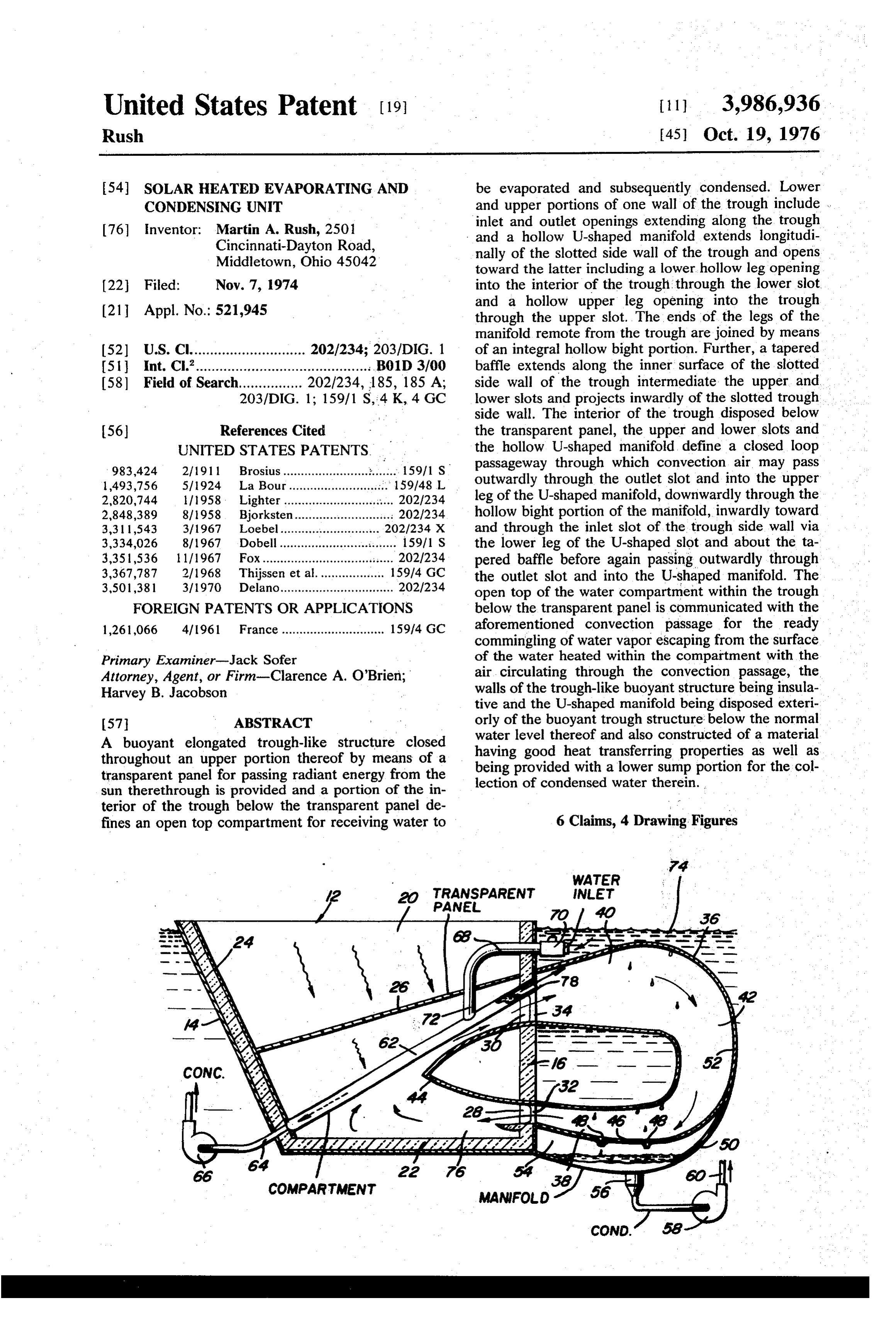
United States Patent (19) 11 3,986,936 Rush [45] Oct. 19, 1976 54). SOLAR HEATED EVAPORATING AND be evaporated and subsequently condensed. Lower CONDENSING UNIT and upper portions of one wall of the trough include . 76) inventor: Martin A. Rush, 2501 inlet and outlet openings extending along the trough Cincinnati-Dayton Road, and a hollow U-shaped manifold extends longitudi Middletown, Ohio 45042 nally of the slotted side wall of the trough and opens toward the latter including a lower hollow leg opening (22 Filed: Nov. 7, 1974 into the interior of the trough through the lower slot (21 Appl. No.: 521,945 and a hollow upper leg opening into the trough through the upper slot. The ends of the legs of the manifold remote from the trough are joined by means (52) U.S. Cl............................. 202/234; 203/DIG. 1 of an integral hollow bight portion. Further, a tapered (5) Int. C.’............................................ B01D 3700 baffle extends along the inner surface of the slotted 58) Field of Search................ 202/234, 185, 185 A; side wall of the trough intermediate the upper and 203/DIG. 1; 159/1 S. 4 K, 4 GC lower slots and projects inwardly of the slotted trough side wall. The interior of the trough disposed below 56 References Cited the transparent panel, the upper and lower slots and UNITED STATES PATENTS the hollow U-shaped manifold define a closed loop 983,424 2, 1911 Brosius........... 15971 S. passageway through which convection air may pass 1493,756 5/1924 La Bour.... ... 159/48 L outwardly through the outlet slot and into the upper 2,820,744 1958 Lighter..... ... 202/234 leg of the U-shaped manifold, downwardly through the 2,848,389 8/1958 Bjorksten...... .......: 202/234 hollow bight portion of the manifold, inwardly toward 3,31 1543 3/1967 Loebel.......... ... 202/234 X and through the inlet slot of the trough side wall via 3,334,026 8/1967 Dobell.......... is a s 15971 S the lower leg of the U-shaped slot and about the ta 3,351,536 1/1967 Fox...................... ... 2021234 pered baffle before again passing outwardly through 3,367,787 2/1968 Thijssen et al................... 159/4 GC the outlet slot and into the U-shaped manifold. The 3,501,381 3/1970 Delano................................ 202/234 open top of the water compartment within the trough FOREIGN PATENTS OR APPLICATIONS below the transparent panel is communicated with the 1,261,066 4/1961 France ............................. 159/4 GC aforementioned convection passage for the ready commingling of water vapor escaping from the surface
Primary Examiner-Jack Sofer of the water heated within the compartment with the Attorney, Agent, or Firm-Clarence A. O'Brien; air circulating through the convection passage, the Harvey B. Jacobson walls of the trough-like buoyant structure being insula tive and the U-shaped manifold being disposed exteri 57 ABSTRACT orly of the buoyant trough structure: below the normal water level thereof and also constructed of a material
A buoyant elongated trough-like structure closed having good heat transferring properties as well as throughout an upper portion thereof by means of a being provided with a lower sump portion for the col transparent panel for passing radiant energy from the lection of condensed water therein. sun therethrough is provided and a portion of the in terior of the trough below the transparent panel de fines an open top compartment for receiving water to 6 Claims, 4 Drawing Figures
WATER
COMPARTMENT
Page 2
Drawing sheet — no readable text.
Page 3
Drawing sheet — no readable text.
Page 4
to the accompanying drawings forming a part hereof,
SOLAR HEATED EVAPORATING AND
CONDENSING UNIT .. .. .
wherein like numerals refer to like parts throughout.
BRIEF DESCRIPTION OF THE DRAWINGS
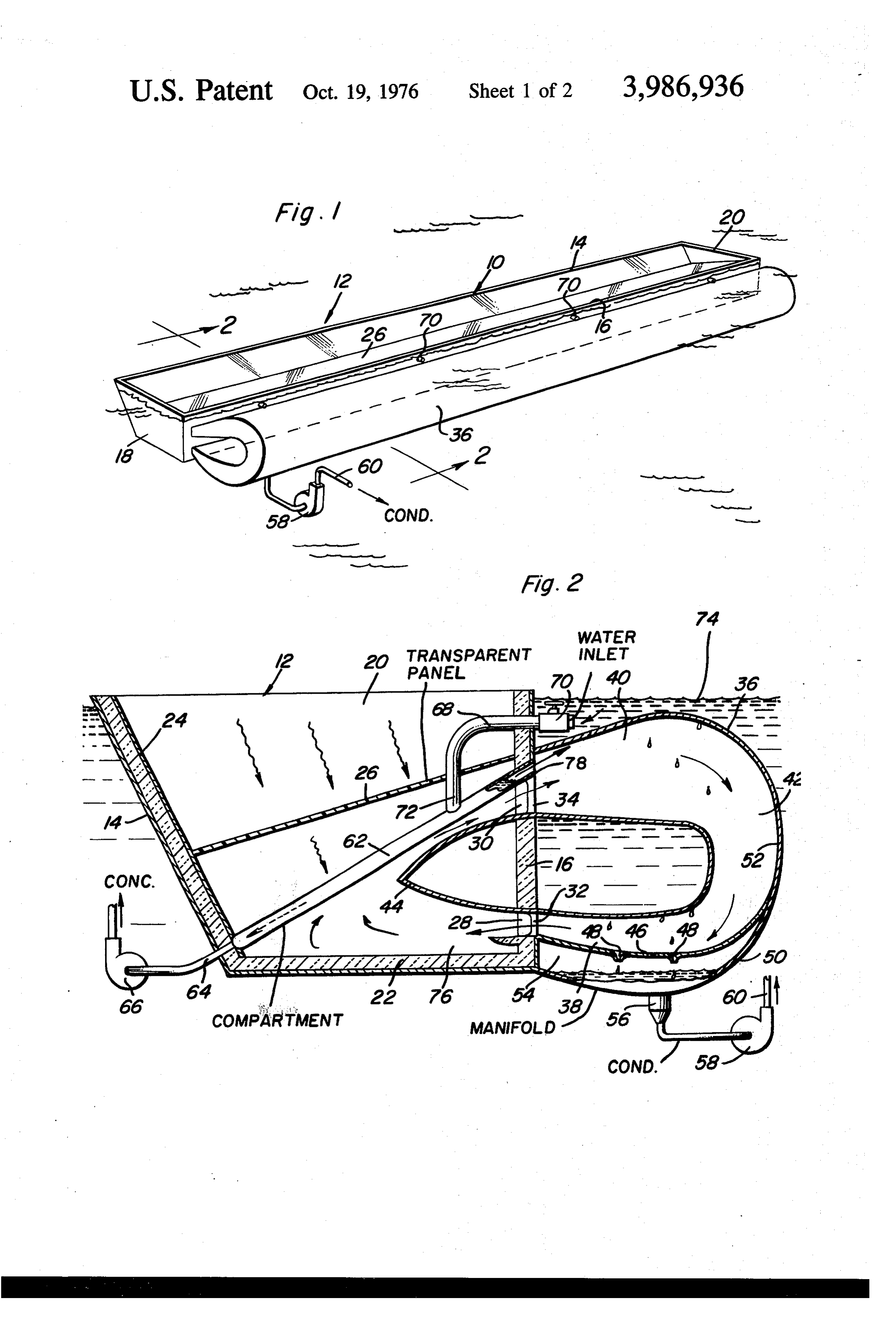
This invention comprises an improvement over the ; FIG. 1 is a perspective view of a solar still con solar powered sea water condensing unit disclosed in structed in accordance with the present invention and my copending U.S. application Ser. No. 485,577, filed illustrating the still afloat upon a large body of salt July 3, 1974. Water;
BACKGROUND OF THE INVENTION FIG. 2 is an enlarged transverse vertical sectional 10 view taken substantially upon the plane indicated by
Solar stills have been heretofore designed but most the section line 2-2 of FIG. 1;
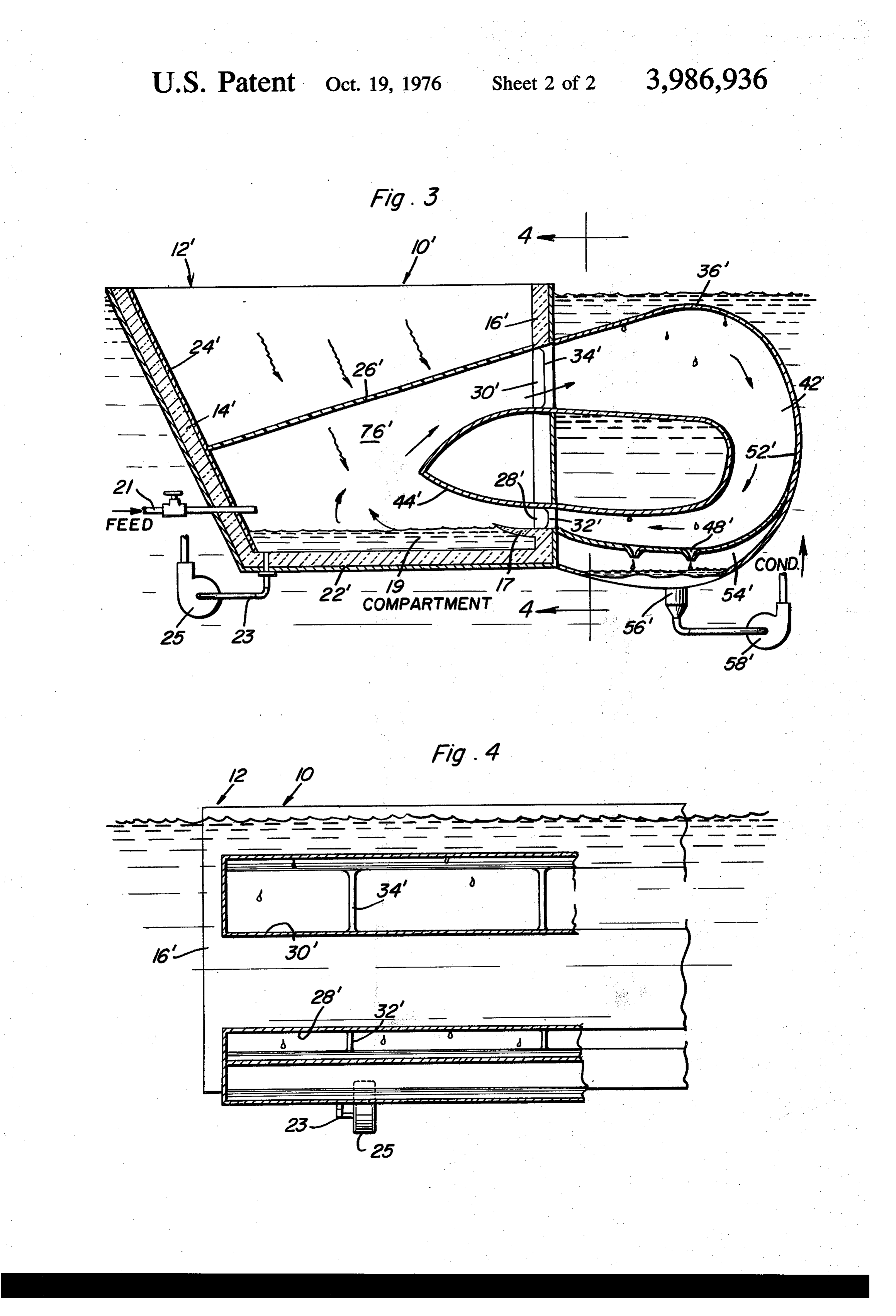
have included structural features which do not adapt FIG. 3 is a vertical transverse sectional view similar the stills for use in an environment dominated by a to FIG. 2 but illustrating a slightly modified form of large body of water. Further, most solar stills are not solar still; and . . .
constructed in a manner whereby the most rapid vapor 15 FIG. 4 is a fragmentary longitudinal vertical sectional ization of water possible is accomplished thereby. view taken substantially upon the plane indicated by While the prior art does include stills which utilize the section line 4-4 of FIG. 3.
some of the basic components of the instant invention DETAILED DESCRIPTION OF THE INVENTION even these previously known devices are not con 20 Referring now more specifically to the drawings and structed in a manner conducive to extremely rapid vaporization and subsequent condensation of water for to10 FIGS. 1 and 2 in particular, the reference numeral generally designates a first form of solar still con a given amount of sunlight incident thereon. Examples of previously patented solar stills utilizing some of the structed in accordance with the present invention. The components of the instant invention are disclosed in 25 still 10 includes an elongated buoyant trough referred U.S. Pat. Nos. 1,302,363, 2,424,142, 3,138,546, to in general by the reference numeral 12 and including opposite side longitudinal walls 14 and 16 intercon- .
3,501,381 and 3,775,257. nected at corresponding ends by means of end walls 18 BRIEF DESCRIPTION OF THE INVENTION and 20. The lower marginal edge portions of the walls or wallportions
The solar still of the instant invention has been de 30 by means of a horizontal14, 16, 18 and 20 are interconnected signed for use in small and large scale installations and bottom wall 22.
is capable of evaporating and condensing quantities of 22 are constructed of heat insulative 20 as well as the bottom wall water which are relatively large in volume for a given lined on their inner surfaces by meansmaterial or at least amount of sunlight incident upon the still as compared tive layer. Also, the inner surface of of a heat insula the longitudinal to the capacity of previously known solar stills. The still 35 side wall 14 is provided with a light-reflective coating may be constructed of such large dimensions as to have or panel 24. W.
a relatively high capacity to provide the fresh water needs of communities of various sizes and it may also anAnupper inclined panel 26 of transparent material closes portion of the interior of the trough 12. The be constructed of such small dimensions to render it panel 26 extends highly adaptable to provide condensed or distilled 40 of the end walls 18between and 20, the upper marginal portions the longitudinal side wall 16 water for use by single persons or small groups of per and a lower portion of the longitudinal side wall 14, the sons such as may find themselves adrift on a large body panel 26 being upwardly inclined toward the longitudi of salt water without a supply of fresh drinking water. nal side wall 16. n The main object of this invention is to provide an . The side wall 16 includes first passage defining means efficient solar still for the purpose of providing distilled 45 in the form of an elongated longitudinally extending water from sea water. . inlet slot 28 formed therein and second passage defin Another object of this invention is to provide a solar ing means in the form of an elongated longitudinally still which may be readily constructed of various sizes extending outlet slot 30 formed therein with the inlet and thus to provide various water distilling capacities. slot 28 being formed in a lower portion of the side wall A still further object of this invention is to provide a SO 16 and the outlet slot 30 being formed in an upper solar still constructed in a manner so that it may be portion of the side wall 16. In order to maintain the operative while floating in a large body of sea water. strength of the side wall 16 both above and below the Another object of this invention is to provide a solar slots 28 and 30, vertical support members 32 and 34 still which will be capable of sufficiently ventilating the are secured across the slots 28 and 30 at points spaced surface of the quantity of water being evaporated by 55 longitudinally therealong.
the still so as to effectively hasten the process of water A generally horizontally disposed and horizontally evaporation. opening hollow U-shaped manifold 36 defining a heat A final object of this invention to be specifically exchange: chamber is disposed exteriorly of the side enumerated herein is to provide a solar still in accor 60 wall 16 and includes hollow lower and upper legs 38 dance with the preceding objects and which will con and 40 interconnected at their ends remote from the form to conventional forms of manufacture, be of sim side wall 16 by means of an integral hollow bight por ple construction and easy to use so as to provide a tion 42. The ends of the legs 38 and 40 remote from the device that will be economically feasible, long lasting bight portion 42 are sealingly secured to the wall 16 in and relatively trouble free in operation. registry with the slots 28 and 30 and an inwardly taper These together with other objects and advantages 65 ing baffle 44 is supported from the inner surface of the which will become subsequently apparent reside in the side wall 16 intermediate the lower and upper slots 28 details of construction and operation as more fully and 30 and projects horizontally inwardly from the wall hereinafter described and claimed, reference being had 16, the slots 30 and 28, and the adjacent portions of the
Page 5
panel 26, manifold 36 and baffle 40 defining a closed outwardly through the slot 30 and into the leg 40 of the loop convection air passageway having isolated upper manifold 36. As the passage of warm air into the leg 40 and lower reaches including the slots 30 and 28, re passes the open upper marginal portion 78 of the com spectively. - partment 62, water vapor from immediately above the The lower leg 38 includes a lower wall portion 46 5 surface of the level of water within the compartment 62 which is dished and includes outlet openings 48 spaced is drawn outwardly through the upper open marginal transversely thereof and longitudinally therealong. edge portion of the compartment 62 and commingles Also, a lower sump wall 50 underlies the bottom wall with the air passing into the leg 40 of the bight portion 46 and is sealingly secured to the outer wall 52 of the 42 from the interior of the upper portion of the trough bight portion 42 and the lower marginal edge of the 10 12 below the panel 26. Then, the moist air passing into side wall 16 to thus define a closed sump 54 into which the manifold 42 contacts the water cooled surfaces of condensed water may flow through the openings 48 for the manifold 36 and causes an appreciable portion of collection within the sump 54. The sump 54 includes an the water content of the moist air to condense out on outlet 56 with which a pump 58 including a discharge the internal surfaces of the manifold 36. The con line 60 is operatively associated for pumping con 15 densed water flows downwardly along the inner sur densed water from the outlet 56 upwardly through the faces of the manifold 36 to the bottom wall 46 and discharge line or pipe 60 to a suitable point of use (not through the openings 48 communicated with the sump shown), the pump 58 being powered by any suitable 54. After an appreciable quantity of condensed water source. - has been collected within the sump 54, the pump 58 is Mounted within that portion of the interior of the 20 utilized to pump condensed water from the sump 54. trough 12 disposed below the transparent panel is a The air passing into the manifold 36 from the slot 30 hollow panel-like enclosure defining a compartment 62 passes downwardly through the bight portion 42 of the for containing sea water to be distilled and the com manifold 36 and then outwardly of the latter through partment 62 is inclined in the same manner but to a the leg 38 of the manifold 36 into the lower portion of slightly greater degree than the panel 26. The lower 25 the interior of the trough 12 via the slot 28. At this marginal edge of the compartment 62 includes a plural point, the latent heat of evaporation lost as a result of ity of outlets 64, therefor opening through the lower the condensation of water on the inner surfaces of the marginal edge of the side wall 14 and having suitably manifold 36 effectively reduces the temperature of the powered pumps 66 operatively associated therewith for air circulating through the manifold 36 and the interior pumping concentrated brine from within the compart 30 of the trough 12 below the container 62. This cooler air ment 62. In addition, a plurality of inlet pipes 68 are enters the lower portion of the trough 12 and is subse spaced along the side wall 16 and include valved inlet quently again heated by and passed upwardly beneath end portions 70 disposed exteriorly of the wall 16 and the container 62 for repeated discharge through the outlet end portions 72 which open downwardly through slot 30 to again commingle with water vapor being the panel 26 and into the compartment 62 at points 35 discharged from the open upper marginal edge portion spaced therealong. The pipes or conduits 68 are pro 78 of the compartment 62. ' vided for intaking fresh sea water into the compartment When the concentration of salt within the compart 62. ment 62 becomes excessive, the pump 66 is operated The entire still, including all of the components here and the valved inlet ends 70 of the pipes 68 are opened inbefore specifically described constitute a mass whose 40 to admit a fresh supply of sea water from the body 74 weight is slightly less than the total volume of water into the compartment 62.
which may be displaced by the still 10 when the latter Because of the high rate of airflow by convection is submerged in a body of water such as the body 74. currents through the air passage 76, water vapor from Accordingly, the still 10 is floatable in the body 74 of the surface of the water within the compartment 62 is sea water with at least the upper extremities of the walls 45 more quickly evaporated.
14, 16, 18 and 20 projecting above the level of the With reference now more specifically to FIGS. 3 and water. However, the entire U-shaped manifold 36 is 4 of the drawings, there will be seen a modified form of disposed below water level when the still 10 is floating still referred to in general by the reference numeral 10' in the body, 74 of water. : , and which is substantially identical to the still 10 with a The interior of the trough 12 below the compartment 50 few exceptions. The various components of the still 10' 62, the slots 28 and 30 and the manifold 36 define a which find their substantial equivalents in the still 10 closed loop passage. 76 through which convection air are referred to by corresponding prime reference nu may readily flow in a clockwise direction as viewed in merals. .. . FIG. 2 of the drawings. * The still 10 differs from the still 10 in that the still In operation, a quantity of sea water is admitted into 55 10' does not include a component corresponding to the the interior of the compartment 62 sufficient to place compartment 62. Rather, the lower portion of the side the level of sea water within the compartment 62 wall 16' disposed below the slot 28' includes a horizon closely, adjacent the open upper marginal edge portion tally inwardly projecting lip 17 and the entire lower 78 thereof which opens into the inlet end of the leg 40 extremity of the interior of the trough 12' disposed of the manifold 36 at the upper marginal portion of the 60 below the lip 17 defines an open top compartment 19 outlet slot 30. The exterior of the compartment 62 is of for receiving sea water. In addition, a plurality of a heat. absorbing color such as black and thus the sun. valved intake pipes 21 open through the lower portion, rays, passing downwardly through the panel 26 and of the side wall 14' below the panel 26' for intaking incident upon the compartment 62 heat the latter and fresh supplies of sea water into the compartment 19 thus the sea water disposed therein. Further, the air 65 and a plurality of outlet pipes 23 open downwardly within the trough 12 immediately below the panel 26 is through the bottom wall 22" and are operatively asso trapped and heated and the air beneath the compart ciated with suitably driven pumps 25 for pumping con ment 62 is warmed thereby and tends to rise and pass centrated brine from the compartment 19. Otherwise,
Page 6
S 6 the structure and operation of the still 10' is similar to manifold and the interior of said trough coacting to the structure and operation of the still 10. However, define a closed elongated loop convection air passage inasmuch as the cool air entering the lower portion of way including upper and lower reaches communicating the interior of the trough 12' over the lip 17 blows through said openings, said compartment opening up directly across the surface of the quantity of water 5 wardly into the upper reach of said passageway, said disposed in the compartment 19, the vaporization of unit being buoyant and floatable in a body of water water into the air passing through the air passageway with the uppermost portion of said manifold disposed 76" is even further hastened. Of course, the water below the water line of said unit, said manifold includ within the compartment 19 is exposed for direct sun 10 ing interior cooling surface portions in good heat trans light incident thereon through the panel 26'. Further, fer relation with the water covered exterior surface the inner surface of the insulative bottom wall 22" may portions of said manifold, a lower portion of said mani be of a heat-absorbing color such as black. fold adjacent the end of said lower reach remote from In FIG. 2 by constructing the condensing unit with said compartment defining a sump in which water con the heating chamber below the water level on the exte densed on the inner surfaces of said manifold may rior of the trough, the entire air passageway 76 includ 15 collect, and means operatively associated with said ing the U-shaped manifold 36 is disposed below the sump for withdrawing condensed water therefrom. exterior water level and the upper reach of the passage 2. The combination of claim 1 including upstanding 76 passing upwardly beneath the compartment 62 and braces disposed in and spaced along said openings including the upper leg 40 of the manifold 36 is up rigidly connected between the portions of said one wall wardly inclined in the direction of convection air there 20 defining corresponding upper and lower extremities of through. each of said openings.
Also, the condensing unit could be land based and 3. The combination of claim 1 wherein said lower yet situated below the water level of an adjacent body opening is spaced at least slightly above the lower ex of water or the condensing unit, the manifold 36, could 25 tremity of the interior of said trough, said compartment be enclosed within a tank through which cooling water comprising the lower extremity of the interior of said from an adjacent source could be rapidly circulated by trough below said lower opening with the latter posi gravity or by a pumping system. tioned to discharge convection air moving through said The foregoing is considered as illustrative only of the passageway from the manifold into said trough horizon principles of the invention. Further, since numerous 30 tally across the surface of a quantity of water within modifications and changes will readily occur to those said compartment. - skilled in the art, it is not desired to limit the invention 4. The combination of claim 1 wherein said compart to the exact construction and operation shown and ment includes water outlet and inlet means for purging described, and accordingly all suitable modifications concentrated water from within said compartment and and equivalents may be resorted to, falling within the 35 admitting a fresh supply of water into said compart scope of the invention. ment.
What is claimed as new is as follows: 5. The combination of claim 1 wherein said side walls 1. A water evaporating and condensing unit including of said trough, at least below said level, are heat insula an elongated trough closed at its top by means of a tive against the transmission of heat through said side transparent panel, said trough including means defining 40 walls.
a water receiving compartment below said panel for 6. The combination of claim 1 wherein said compart receiving water to be evaporated therefrom and subse ment includes a hollow panel shaped enclosure sup quently condensed, said compartment being located ported within said trough in at least slightly inclined within said trough for direct overhead sunlight passing position with said hollow panel inclined upwardly downwardly through said transparent panel to be inci 45 toward said one side wall of said trough, the upper dent upon said compartment, said trough including a marginal portion of said hollow panel being open and pair of upstanding opposite side walls in the elongated extending along a major portion of the length of said direction, an elongated heat exchange manifold sup upper opening, said open upper marginal edge portion ported exteriorly along one of said side walls of said opening directly into an upper portion of said manifold trough, said one side wall having vertically spaced elon 50 through said upper opening.
gated upper and lower openings formed therein, said
Provenance
- Collection
- Cited prior art
- Original PDF
- patentimages.storage.googleapis.com →
- Filed
- 1974-11-07
- Pages
- 6
- Method
- pdftotext (the PDF's own text layer) + pdftoppm 300dpi page scans
- Source
- Google Patents bibliographic record
- Granted
- 1976-10-19
- Inventors
- Martin A. Rush
- Transcribed from
- patentimages.storage.googleapis.com →