patent · US4011857
Solar energy converter and elongated Fresnel lens element
15 March 1977
Page 1 — bibliographic record
350 a 4.52 SR
United Stat ll 4,011,857 Rice 45 Mar. 15, 1977 54) SOLAR ENERGY CONVERTER AND side margins of the focusing area but are of helical ELONGATED FRESNEL LENS ELEMENT configuration longitudinally thereof in order to focus - to Inventor: Harold D. Rice, 25th and McGee 22 Filed:
Trafficway, Kansas City, Mo. 64141
the solar radiation onto a narrow zone spaced from the concentrator which is parallel with the side margins of the focusing area. In its preferred form, the focusing surfaces define a Fresnel-type concentrator. A rela tively large number of focusing surfaces are provided 21 Appl. No.: 634,763 per unit width of the concentrator to minimize the (52 U.S. Cl. ............................... 126/270; 126/271; effective thickness thereof and the accuracy and integ 350/21 1 rity of the focusing surfaces is obtained and preserved 151 Int. Cl* ............................................ F24J 3/02 in the focusing unit by forming thereof from a sheet of 58 Field of Search ........... 126/270, 271; 237/1 A; synthetic resin material which has been forced against 350/21 a cylindrical die having a continuous, helical, focusing
surface defining groove in the circumference thereof which thereby causes such surfaces to be at an angle
UNITED STATES PATENTS relative to the direction of travel of the sheet during 937,013 10/1909 Severy ............................... 126/27 | forming and thereby in the final product, but with a 1. 101.00 l 6/1914 Willsie ............................... 126/27 | built-in warp in such surfaces longitudinally thereof to l, 130,871 3/1915 Willsic ............................... 126/27 maintain a nonangular focusing zone spaced from the 3,915, 148 l ()/ 1975 Fletcher et al. ............... 35()/21 | X concentrator. Forming of the concentrator against a Primary Examiner-Kenneth W. Sprague continuous surface die permits fabrication of a radia tion energy focusing sheet of any desired length having
Attorney, Agent, or Firm-Schmidt, Johnson, Hovey & a series of repeat pattern Fresnel surfaces which merge Williams smoothly and uninterruptedly one into another with the (57) ABSTRACT effective focus thereof extending longitudinally of the A solar energy concentrating and collecting assembly sheet even though the focusing surfaces are at an angle relative to the focus zone.
including a formed synthetic resin radiation concentra tor having a series of elongated, generally rectilinear, side-by-side, parallel solar ray focusing surfaces that extend in a direction which is at an angle relative to the 32 Claims, 14 Drawing Figures
Page 2
Drawing sheet — no readable text.
Page 3
Drawing sheet — no readable text.
Page 4
Drawing sheet — no readable text.

Page 5
Drawing sheet — no readable text.
Page 6
cipal energy source must be substantially maintenance
SOLAR ENERGY CONVERTER AND ELONGATED free for extended periods of time. FRESNEL LENS ELEMENT Many of the problems inherently associated with radiation conversion apparatus of the concentrating
This invention relates to solar energy conversion type have been overcome in the present invention by apparatus and particularly to an improved Fresnel-type the provision of a lightweight radiation focusing sheet radiation concentrator which is less expensive without element which may be fabricated and placed in use at loss of efficiency than units heretobefore available, a much lower cost than heretofore possible and which while at the same time being readily adapted for use in allows the utilization of much less complex, lower cost a multitude of different applications. O and more maintenance free tracking equipment for Devices for converting solar radiation to other en maintaining the radiation concentrator in proper orien ergy forms have been known and used since ancient tation relative to the sun's rays.
times, but efficiency versus unit cost ratios have pre provide It is therefore a primary object of this invention to vented widespread adoption and use of such equipment 15 solar energy conversion apparatus including a as either primary or alternate energy sources. Flat plate radiation focusingconcentrator unique radiation which has a series of surfaces extending at an angle to a collectors, which may or may not have an energy longitudinal length of the concentrator but which are absorbing medium such as water running thereover, are the least expensive solar converters, but suffer from the longitudinally radiation to be warped in directions to cause the solar focused onto an elongated zone extend disadvantage of low efficiency and the concomitant 20 ing along the axis of the concentrator sheet for heating need for large surface areas exposed to the sun's rays. an energy absorbing medium flowing through a conduit Efforts to decrease the overall size of the conversion located at the units by use of radiation concentrating assemblies as disposition of the focusingfocusing zone of the assembly. Angular component parts thereof have met with only limited of the sheet allows fabrication surfaces relative to the axis success because of the disproportionate complexity of a concentrator using and increase in cost relative to the decrease in size. One 25 a cylindrical drum having a continuous helical groove major factor inherently restricting utilization of solar form in the outer surface thereof configured and arranged to collection apparatus as a substitute for other fuel sheet the as it desired focusing pattern in the concentrator is moved past the forming die.
sources has been the problem of storage of the energy collected for use either at a point remote from the 30 provide a solar important
It is a further object of the invention to radiation collecting device or at a time subsequent cylindrical forming die hasasgrooved converter described wherein the surfaces therein thereto. Flat plate collectors require a relatively large which form a Fresnel-type focusing radiation storage capacity because of the low temperatures in trator with the Fresnel surfaces presenting aconcen repeat volved in the conversion process. When water is used pattern thereof along the longitudinal length of the as the solar energy absorption medium, relatively large 35 sheet element. In this manner, the concentrator may be volumes of such water must be provided to act as a heat made of any desired length to fit a particular applica sink for storing the energy. This then necessitates utili tion while at the same time allowing disposition of the zation of large storage tanks and the like which are concentrators in any required orientation and dispo expensive in themselves and also require extensive sition relatively.
insulation to preclude heat losses. 40 A still further important object of the invention is to Solar energy conversion equipment which relies provide a solar converter and Fresnel-type concentra upon radiation concentrators to collect the sun's rays tor wherein the thickness of the Fresnel unit may be generate much higher temperatures than flat plate col minimized without sacrifice in the efficiency of the lectors and thus permit the utilization of smaller structure by virtue of the provision of a relatively large amounts of the storage medium to effect transmittal of 45 number of focusing surfaces per unit width of the con energy from the collector to the point of use. However, centrator with each surface in cross section represent as heretofore observed, radiation concentrating equip ing a relatively accurate segment of which would other ment is much more complex than flat plate devices, wise be a thick semi-cylindrical lens of the same focal particularly in view of the fact that sun-tracking appa length. - ratus is preferably included in the overall package to 50 A particularly important object of the invention is to maintain the concentrator in facing relationship to the provide a less costly method of producing elongated radiation source, and efficient means must be provided Fresnel-type solar radiation concentrators of any se for converting the sun's rays into a useful form of ther lected length by virtue of the fact that synthetic resin mal energy, whether it be for heating or cooling pur material of required width may be extruded from a poses. 55 conventional slit die and then passed between a One of the problems which must be dealt with in grooved cylindrical forming die and a chilled backup fabricating solar converters of the radiant energy con cylinder. In this way, a radiation focusing sheet may be centrating types is the need for incorporating sun formed which continues in length so long as the resin is tracking mechanisms into the mechanical arrangement directed to the forming area. Of prime significance in of the devices to keep the concentrator oriented with 60 this respect is the fact that the provision of a large the sun. Since radiation focusing and concentrating number of focusing surfaces in the face of the sheet, structures heretofore available have been relatively formed therein by the cylindrical die, permits fabrica heavy and of unwieldy size, tracking devices have of tion of a relatively thin radiation concentrator having necessity involved equipment which was relatively un the focal effect of a relatively wide and thereby nor economic to install, not only from an operating point of 65 mally thick lens element. As a consequence, there is view but also in terms of the energy needed to maintain not only a significant saving in the cost of the material proper functioning of the equipment over long time required for fabrication of the unit, but the resulting intervals. Units designed to act as an alternate or prin radiation deflector is much simpler and easier to form
Page 7
than previously possible, using a minimum of construc from one end of the sheet illustrated in FIGS. 1 and 2 tion personnel. to the opposite end thereof,
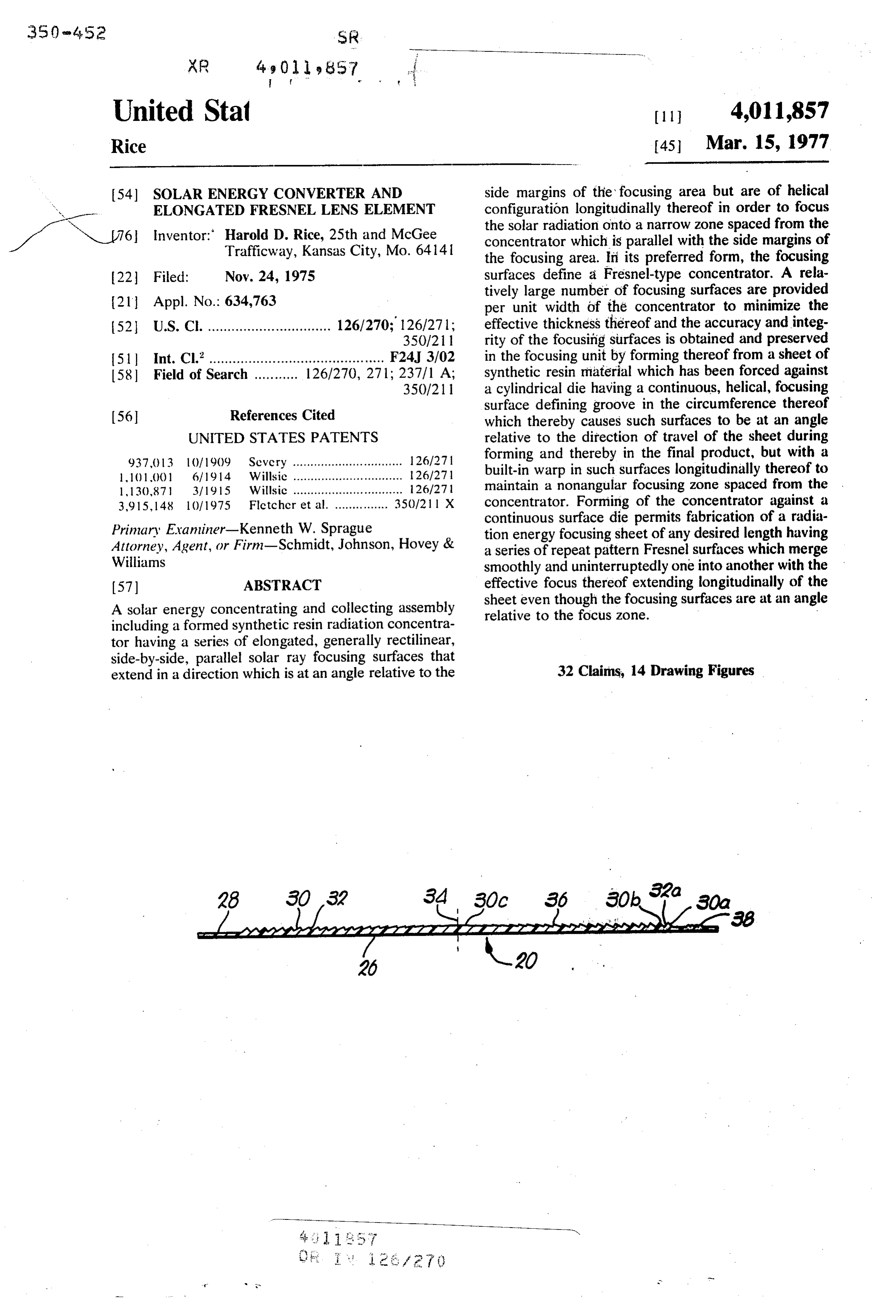
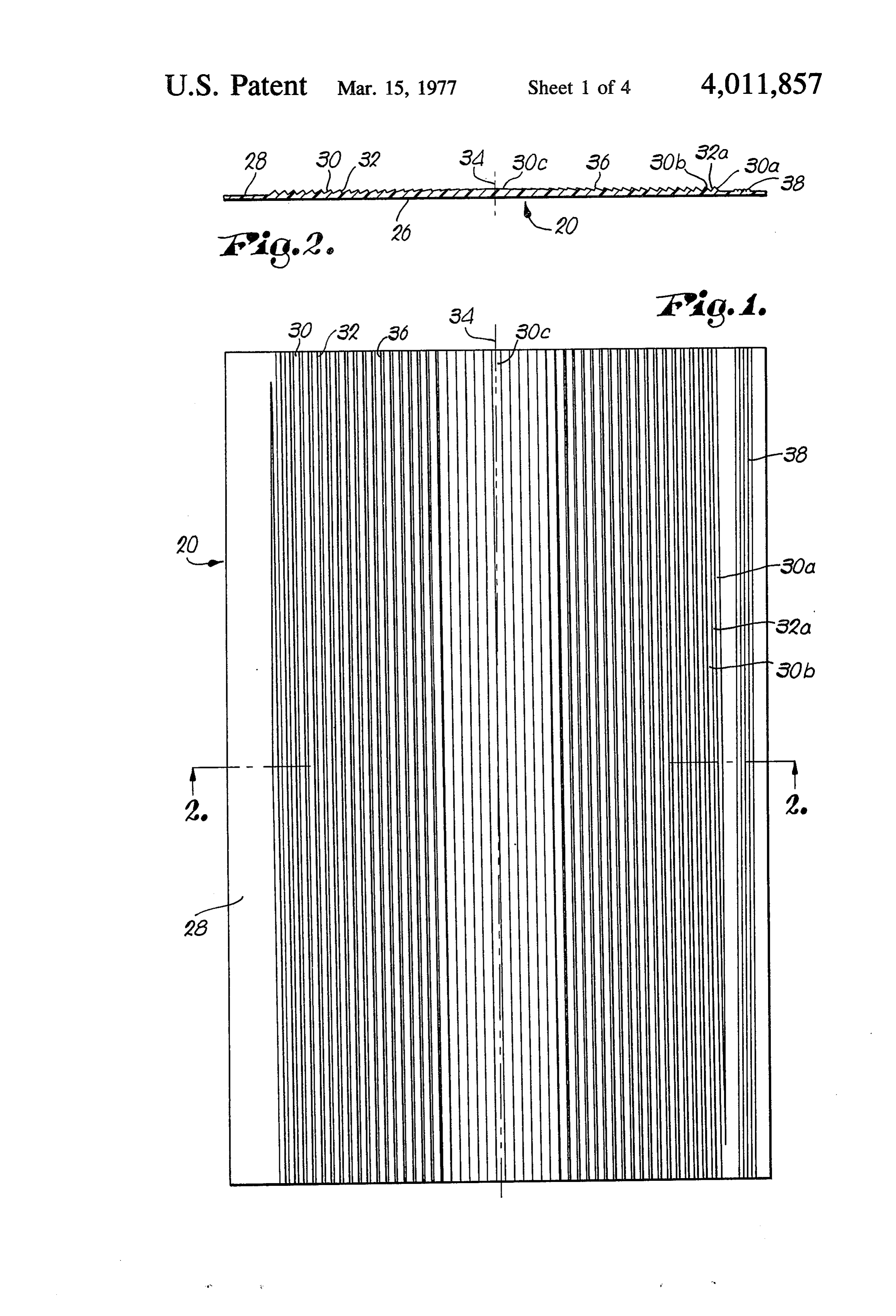
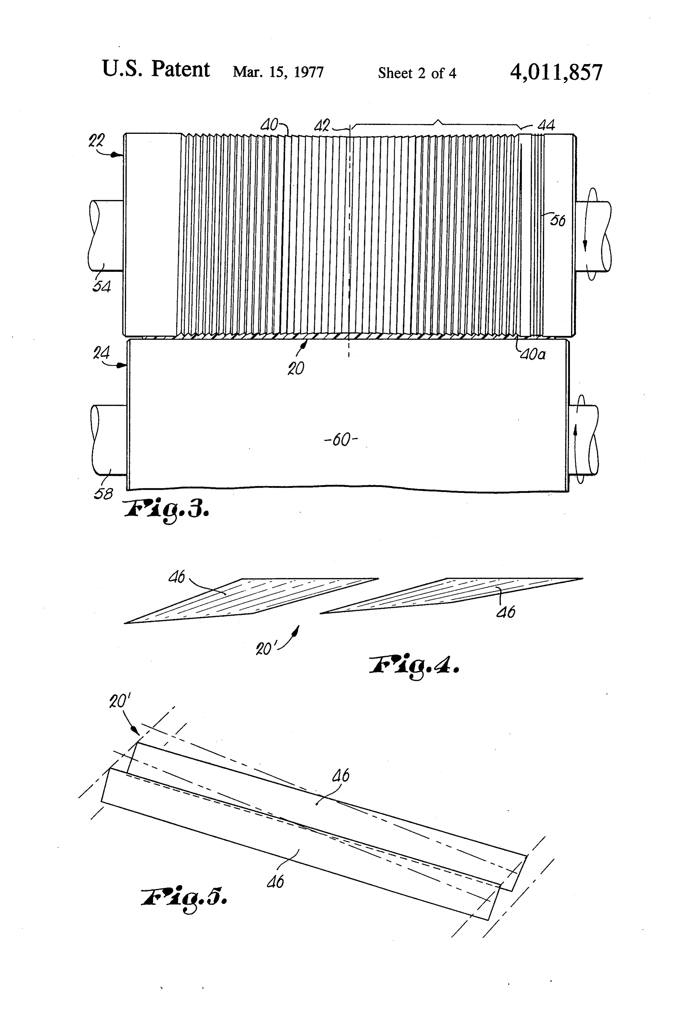
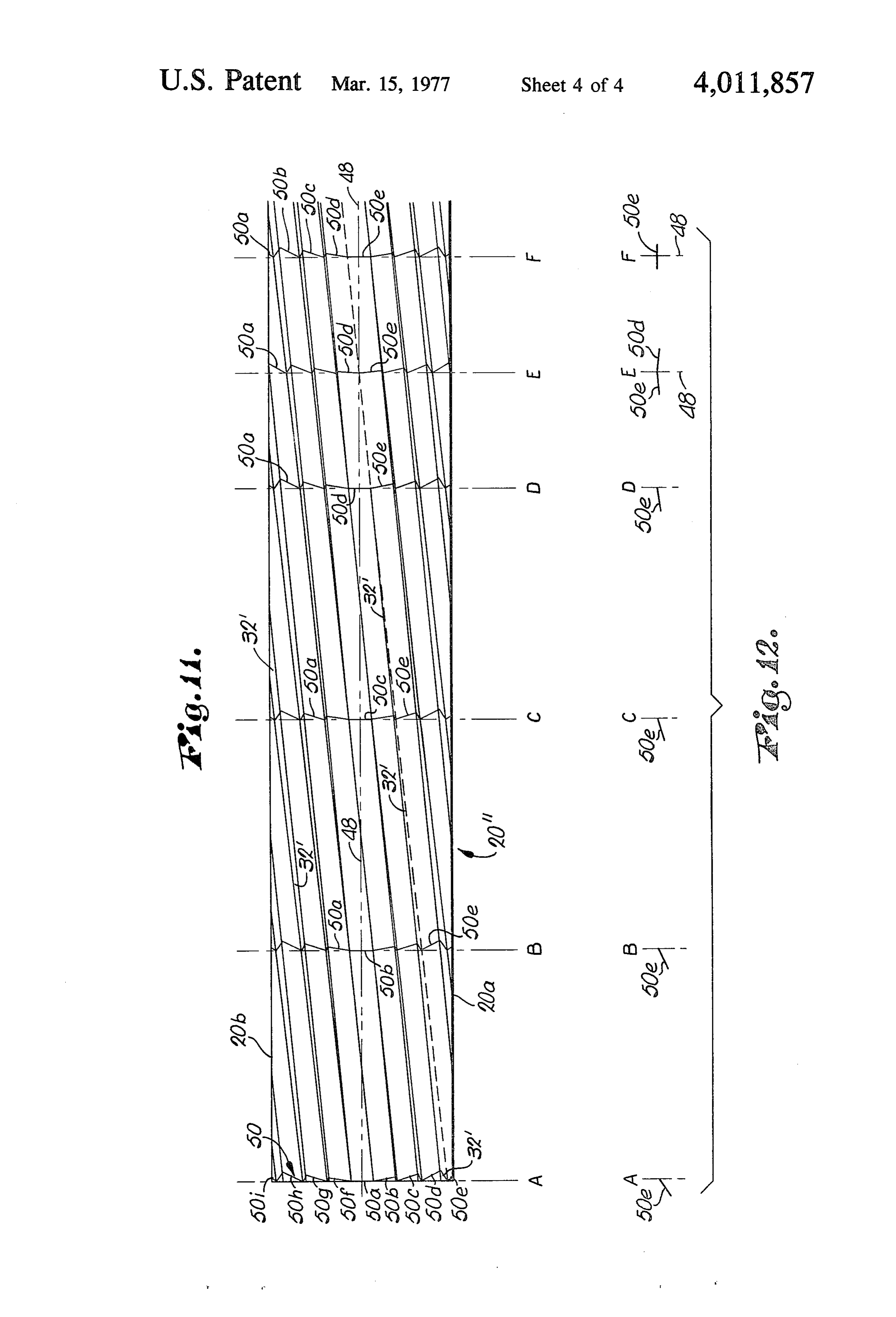
Also an important object of the invention is the way FIGS. 7, 8, and 9 are vertical cross-sectional views in in which extrusion forming of the resin sheet followed diagrammatic form taken substantially along the lines by embossing thereof wich cylindrical grooved die al 7-7, 8-8, and 9-9 respectively of FIG. 6; lows exact reproduction of the focusing surfaces on a FIG. 10 is a diagrammatic representation of adjacent repetitive basis with little wear on the die by virtue of radiation focusing surfaces of the solar energy concen the fact that embossing takes place while the resin is in trator viewed along the length of such surfaces to illus a semi-fluid or readily formable, somewhat plastic con trate the warp therein longitudinally of the sheet; dition. This is extremely important when it is appreci O FIG. 1 I is a diagrammatic representation on an en ated that all rounded as opposed to sharp cutoff angles larged, exaggerated scale illustrating the way in which and edges operate to reflect radiant energy and thereby fabrication of the Fresnel-type radiation concentrator contribute to loss of conversion efficiency. using a cylindrical forming die wherein the grooves Also an important aim of the invention is to provide defining the focusing surfaces are in a helical pattern an improved process for manufacturing solar radiation 15 around the cylinder to produce a repeat pattern of concentrating elements for solar energy converters Fresnel surfaces on a flat sheet, with such surfaces permitting reproduction on an extremely accurate basis warped in a manner to maintain the focal point along of a Fresnel-type radiation deflecting surface which the center line of the sheet;
would not be practical if a series of circumferentially FIG. 12 is a schematic representation of the angle of extending, individual die grooves were provided in a 20 the bottommost focusing surface commencing at the die cylinder, but which becomes economically and line A of FIG. 11 and illustrating the angularity of such technically feasible when the embossing cylinder em surface at the lines B, C, D and F upon rotation of the ploys a continuous, helically configured forming forming die through four complete revolutions; groove. FIG. 13 is a schematic perspective representation of A further important object of the invention is to 25 a solar energy converter embodying the preferred Fres provide a Fresnel-type concentrator of indefinite nel solar radiation concentrator of this invention with a length wherein any number of Fresnel focusing areas conduit for conveying an energy absorbing medium may be provided across the width of the sheet element through the radiation focus zone illustrated as being for focusing of radiation onto a plurality of parallel located at the axis of swinging movement of the con zones spaced from the radiation concentrator, thus 30 verter whereby the latter may be maintained in direct increasing the adaptability of the converter for differ facing relationship to the sun; and ent applications while still employing the same basic FIG. 14 is a vertical cross-sectional schematic view of type of Fresnel forming equipment. another type of radiation concentrator made in accor Other objects of the invention and advantages dance with this invention provided with a plurality of thereof will be explained or become obvious as the 35 Fresnel focusing areas thereon which direct solar radia following specification progresses. tion onto respective focal points, thus shortening the In the drawings: overall distance between the radiation concentrator FIG. 1 is a plan view of a Fresnel-type solar radiation and a collection point therebelow, which has advantage concentrator element constructed in accordance with in certain applications of limited usable space. the preferred concepts of the invention and thus pro 40 The solar energy concentrator broadly designated by vided with a series of slit guide tracks along one margin the numeral 20 in FIGS. 1 and 2 is preferably fabri of the sheet, along with Fresnel radiation focusing sur cated of synthetic resin material which is extruded in faces at an angle relative to the guide tracks and sheet form and then passed between a forming die 22 of thereby with respect to the longitudinal axis of the cylindrical configuration as depicted in FIG. 3, backed sheet; 45 up by a chill cylinder 24. The concentrator sheet 20 is FIG. 2 is a vertical cross-sectional view taken sub illustrated as being of a length produced by one rota stantially on the line 2-2 of FIG. 1; tion of rotary die 22, although it is to be appreciated FIG. 3 is an essentially diagrammatic representation that the preferred process for producing concentrator of a cylindrical forming die having a continuous helical 20 as described herein results in fabrication of a sheet groove in the periphery thereof configured to form the 50 radiation concentrator element of length limited only Fresnel radiation focusing surfaces in the sheet illus by supply of sheet material to the nip between forming trated in FIGS. 1 and 2, along with a chilled backup die 22 and chill cylinder 24, with the Fresnel pattern cylinder rotatable adjacent the forming die; depicted in FIG. 1 being repeated throughout the FIG. 4 is a diagrammatic perspective view of adjacent length of the elongated formed sheet. Fresnel radiation focusing surfaces viewed along the 55 As is well-known, a Fresnel radiation concentrator, axis of a formed sheet, with the angles thereof being whether it be of the diffraction or reflective type, has a somewhat exaggerated and omitting the wall face of the series of focusing surfaces which represent segments of sheet normally interconnecting such adjacent surfaces; a spherical or semi-cylindrical lens member of equiva FIG. 5 is a diagrammatic perspective view of adjacent lent length. In the case of an elongated radiation con radiation focusing surfaces of the Fresnel sheet element 60 centrator, the focusing surfaces comprise elongated as shown in FIGS. 1 and 2, illustrating the angular warp segments which are projected from an imaginary semi in adjacent surfaces, with the length thereof being cylinder which passes through the side margins of the shortened to more clearly delineate the longitudinal radiation diffractor or reflector. Although the individ variation in the angularity of the surfaces; ual focusing segments to be exactly representative of a FIG. 6 is a longitudinal vertical sectional view 65 semi-cylindrical lens should theoretically have curved through one of the radiation focusing surfaces of the outer faces, in practice, these surfaces can be trans Solar energy concentrator to illustrate the variation in versely straight as tangents of such curves if the number the angularity of such surfaces longitudinally thereof of individual segments is sufficiently large to focus Solar
Page 8
radiation passing therethrough or reflected therefrom of sheet 20 to serve as a guide for a slitting mechanism to points very close to a line extending along the line to remove excess sheet material from opposed side represented by an infinite number of end-to-end focal edges of the Fresnel-defining pattern formed in points for the concentrator. grooved side 28 of the concentrator 20. The grooves or Since in the preferred converter of this invention the 5 tracks 38 are parallel with center line 34 even though concentrator 20 has focusing surfaces of the order of surfaces 30 and thereby faces 32 are at an angle with 0.05 in. in width, the faces of the individual radiation respect to such center line and the groove tracks, by focusing surfaces may be transversely flat as opposed to virtue of formation of the Fresnel diffractor or reflector curved without significant sacrifice in the overall effi through utilization of a forming die such as the grooved ciency of the element. FIGS. 1 and 2 illustrate focusing 10 cylinder 22 illustrated in FIG. 3. Tracks 38 also serve as surfaces twice as wide as actually contemplated for the means for orienting a slitter operable to cut the sheet commercial version of the concentrator 20 for pur 20 in a direction transversely thereof at and desired poses of clarity and to better illustrate the various an locations and to make certain that such cross cuts are gles of the radiation concentrating surfaces. It is to be in true perpendicular relationship to the center line 34. understood in this respect that the invention is not 15 In a conventional Fresnel lens, solar rays passing limited to a specific number of focusing faces per unit through the lens element are focused at a common width of the sheet member, but it is to be appreciated point in predetermined spaced relationship from the that for any given focal length, the fewer the number of lens which is a function of the curvature of the outer solar ray diffracting or reflecting surfaces, the thicker surface of the lens component. In the case of a cylinder the sheet must be. In the case of the preferred concen- 20 type Fresnel lens, the light rays are focused onto a line trator having a focal length of approximately 23 in. and spaced from and parallel with the axis of the semicylin focusing surfaces of the order of 0.05 in., the sheet drical lens. The manufacture of a relatively thin, elon element can have a thickness no less than about 0.07 gated Fresnel reflector or diffractor presents substan in. As the number of reflecting or diffracting surfaces tially insurmountable problems when relatively narrow per unit width is decreased, the sheet thickness must 25 ray focusing surfaces are employed because of difficul also be increased, with an upper limit of about 0.125 in. ties encountered in fabrication of the groove forming being practical insofar as thickness is concerned when die for the radiant energy concentrator. This is true the source of the sheet material is a plastics extruder. In whether or not the means for embossing a synthetic the case of thermoplastic sheets formed by other. resin sheet or equivalent component comprises a rotary means, the thickness of the concentrator blank can be 30 embossing cylinder or a flat grooved die plate. Assum even greater. In large measure, the thickness dimension ing for example that it is desired to fabricate a radiant of the concentrator sheet is a function of the angle of energy concentrator having 400 ray focusing surfaces the face between the outermost edge radiation deflect across a 20 in. span, it is to be appreciated that the ing surface and the next adjacent surface, and the accumulation of errors in any effort to mill such greater the angle, the thicker the sheet blank must be to 35 grooves into a cylindrical or flat die will produce such accommodate such angle. irregularities and inaccuracies in the dimensions of the As most evident from FIG. 2, the sheet 20, which is grooves being formed as to make the resulting die of this instance is assumed to be of a transparent synthetic little practical utility in preparation of an efficient radi resin material such as a polycarbonate, has a flat face ant energy concentrator. For example, if a 5 to 10 26 and an opposed grooved side 28. A series of trans- 40 percent error occurs during adjustment of the machine versely inclined, longitudinally warped focusing Sur to form the second groove in the die, this error will faces 30 are joined by respective angular faces 32 accumulate along with additional errors across the which extend between adjacent margins of proximal width of the die and very quickly render the entire tool surfaces 30. Viewing the righthand side of the concen worthless. Even sophisticated tape-controlled ma trator 20 as shown in FIG. 2, it can be seen that the 45 chines available to industry today are incapable of rightmost focusing surface 30a is at the greatest angle operating within limits that would prevent accumula relative to flat face 26 and is joined to the next adjacent tion of error in the grooving process to an extent that focusing surface 30b by inclined, elongated, longitudi the operator could be assured that each of the ray nally extending connector face 32a. The surfaces 30 focusing surfaces is of the proper dimensions across the successively decrease in relative angularity with respect 50 entire width of the sheet, which as indicated is prefer to flat face 26 as the center line 34 of concentrator ably at least of the order of about 20 in. or the like. The sheet 20 is approached by virtue of the fact that each of problems referred to, though, are obviated when the the surfaces 30 is configured to be parallel with a pro forming die comprises a cylinder having a helical jection from corresponding tangents to a semi-cylinder groove in the outer face thereof since any error in the whose end margins are located at the outermost side 55 initial setup simply continues without accumulating extremities of the grooved Fresnel defining pattern throughout the entire groove cutting process. formed in the side 28 of sheet 20. Thus, the innermost Although the helical lens forming groove in the cylin surface 30c bisected by center line 34 is longitudinally drical die 22 produces angular focusing surfaces in the warped as will be explained but is essentially flat at the side 28 of sheet 20 which are at an angle with respect center of the sheet in a longitudinal direction. It is also 60 to the center line 34 thereof, it has now been discov apparent from FIG. 2 that the groove defining surfaces ered that the groove defining faces in die 22 can be and faces of concentrator sheet 20 are configured and accurately configured and arranged to produce focus arranged such that the peaks36 presented by the zones ing surfaces 30 which are of longitudinally warped of merger of respective faces 32 with surfaces 30 all lie shape, which maintains the focal zone of the sheet in a common plane which is substantially parallel to the 65 along a center line parallel with the longitudinal axis of plane of flat face 26. the sheet. As a consequence, during fabrication of die A series of elongated, transversely V-shaped slit guid 22, the lens forming grooves therein can be machined ing tracks or grooves 38 are also formed in the side 28 in such a manner that considering any one point on the
Page 9
circumference of the die, the groove angle is constantly tinuously increase in angularity in a direction away and uniformly changed so that it merges smoothly into from line 48. In view of the fact that the Fresnel pattern the desired angularity of the next adjacent surface de is formed in sheet 20' by a helical groove, the angular fining groove. If, for example, die 22 has a Fresnel surfaces which in effect "run off the side margin 20b forming continuous groove 40 therein across 20 in. of commence again at margin 20a alignment with the run the face thereof and if such grooves form deflecting off point and of the same angularity but in the opposite surfaces in sheet 20' of about 0.050 in. width, it can be direction. It is also to be observed from FIG. 11 that the appreciated that 200 of such groove segments will be surface 50b is essentially flat at repeat line B; the same provided between the center line 42 of die 22 and the is true as to surface 50c at line C, surface 50d at line D end margins of the groove 40, as for example indicated O and surface 50e at line F. Transverse reference line E by the number 44. With these hypothetical dimensions, illustrates the fact that halfway between repeat refer the outermost groove wall 40a will be at an angle of ence lines D and F, the surfaces 50e and 50d are in about 40 and continuously decreases toward the cen clined in opposite directions but at the same angle. Of ter line 42 through a variation of about 0 12" for each particular significance is the fact that although the 360 extent thereof around the circumference of die 5 deflecting surfaces are on a bias longitudinally of the 22. This 12 minute slope is illustrated diagrammatically sheet, the effective focusing points thereof are aligned in FIGS. 4-9 inclusive, where it is to be seen from FIG. in parallel relationship to center line 48. It is also ap 6 that a representative focusing surface of the sheet 20' parent from FIG. 11 that the Fresnel pattern formed in formed between die 22 and backup cylinder 24 has an sheet 20' may be continued indefinitely with the cen inclined radiation deflecting face 46 which continu 20 ter of focus of deflecting surfaces 50 along center line ously changes in slope from one end of sheet 20' 48 notwithstanding the longitudinal angularity of such toward the opposite end thereof. Variation in slope of surfaces.
wall surfaces 46 is further illustrated in FIGS. 4, 5 and It has also been discovered that by the use of a ther 10. Inclined faces 32 interconnecting adjacent spaced moplastic synthetic resin material for producing con edge margins of proximal inclined radiation deflecting 25 centrator sheet 20 and to fabricate such element be surfaces 46 are also longitudinally warped as is evident tween die 22 and chill cylinder 24, the plastic material from FIG. O. is capable of displacing transversely to an extent neces The relative orientation and shape of the ray deflect sary to provide compensation for the variable width of ing surfaces formed in a concentrator sheet 20 may be the wall faces 32 which join adjacent deflector surfaces better understood by reference to the diagrammatic 30 30 of the sheet 20 along the length of the radiation representations of FIGS. 11 and 12, with FIG. 11 show concentrator. Referring to FIG. 11, it can be seen that ing a sheet 20' wherein the radiation deflecting Fres the effective width of wall faces 32' gradually decreases nel-type grooves are longitudinally warped in order to to zero at center line 48 and then to the same degree maintain the Zone of focus of the sheet along center increases on the opposite side of the center line. Since line 48 even though such surfaces are at an angle rela 35 the die 22 and sheet 20 passed thereunder do not move tive to such line. For simplicity of illustration, the sheet relatively, it is to be recognized that the lateral dis 20' is shown as having only eight ray deflecting sur placement of individual portions of the embossed sec faces, although it is to be understood that the principles tion of the synthetic resin which occurs during forming detailed with respect to sheet 20' apply to a concentra of the Fresnel pattern also provides required compen tor having a much larger number of deflecting surfaces, 40 sation for the double warp involved in the radiation as for example the preferred sheet having 400 angular displacement surfaces of the concentration as well as in surfaces of equal width across a panel 20 in. wide. It is the wall faces joining adjacent edges thereof. The cylindrical die 22 is preferably constructed of a to be emphasized in this respect that the concepts of wear-resistant this improvement are applicable to a sheet of any de metal and mounted for rotation about a sired width, subject only to proper structural support 45 fixed horizontal axis through the support shaft means therefor, and one of the advantages of the invention is 54. In addition to the helical groove 40 in the outer face the fact that a relatively wide concentrator sheet may thereof, the surface of die 22 has a series of circumfer be fabricated in accordance with the precepts hereof. entially extending grooves 56 therein coaxial with shaft The only requirement is that an accurate and precise means 54 located in disposition to form the guide helical groove be formed in the circumferentially ex 50 tracks 38 in formed sheet 20. Backup cylinder 24, also tending surface of die 22 for embossing the sheet mate preferably fabricated of wear-resistant metal, has a rial forced thereagainst. smooth outer face and rotates in the opposite direction Again referring to FIG. 11, the reference line A from die 22 about shaft means 58 which turns about an across sheet 20' represents the commencement of one axis parallel with the axis of shaft means 54. If desired, Fresnel repeat pattern, with the transverse configura 55 cylinder 24 may be of hollow chamber configuration to tion thereof at such line being indicated by the irregular permit a cooling fluid such as water to be introduced schematic cross sectional line 50. The radiation de into the interior thereof on a continuous basis to chill flecting surface 50a which is innermost along line A is the outer cylindrical surface 60 of the backup member. essentially flat along line A and thereby oriented in In this manner, the Fresnel pattern embossed in sheet perpendicular relationship to the sun's rays at such 60 20 may be immediately set in the thermoplastic mate point. However, since the angularity of surface 50a rial as the latter emerges from the space between the increases as the next repeat pattern line B is ap grooved surface of die 22 and cylindrical surface 60. proached, the zone of focus of surface 50a remains in For illustrative purposes only and not as a limitation on longitudinal alignment with center line 48, as is evident the scope of this invention, forming die 22 may be of a from the schematic cross sectional representation at 65 circumference to provide a Fresnel pattern which re that point. In a similar manner, surfaces 50b to e inclu peats every 36 in. when a 20 in. wide concentrator is sive decrease in angularity as they progress toward line being fabricated having individual radiation deflecting 48, while surfaces 50f to i inclusive gradually and con surfaces of the order of 0.050 in. wide.
Page 10
A typical use for concentrator screen 20 is illustrated Although the converter 66 having a diffraction in FIG. 13 wherein it can be seen that the converter 66 screen or Fresnel-type concentrator as an operative has a transparent formed sheet 20 which is carried by component thereof is the preferred embodiment of the an elongated, transversely V-shaped housing 62 pro present invention, it is to be understood that a reflec vided with an elongated conduit 64 extending there- 5 tor-type lens may be used in place of screen 20, with through adjacent the apex of the V unit. Conduit 64 is means being provided to form a mirror face on the adapted to convey a radiant energy absorbing medium grooved surface of the formed sheet to focus radiant such as water through housing 62 to and from a point of energy on a conduit again located at the focal zone of use. The dimensions of the housing 62, as well as the the reflector. Vacuum metalizing techniques make location of pipe or conduit 64 relative thereto, are 10 such mirror application practical at a reasonable cost. chosen to place the longitudinal axis of the conduit The formed radiation concentrator 20' illustrated Substantially at the zone of focus of concentrator sheet in FIG. 14 shows three side-by-side Fresnel-type ray 20. At least the part of conduit 64 within housing 62 is deflecting screens across the width of the sheet and preferably coated black to enhance absorption of radi extending longitudinally of the latter. In this case, a ant energy by the water or other energy absorbing 15 conduit would be located at the focal zone of each medium flowing therethrough, and in addition, means Fresnel-type lens section and in parallel relationship (not shown) is preferably coupled to the housing 62 for longitudinally of the converter. Here again, the number Swinging the latter about the axis of conduit 64 to main of Fresnel-type radiant energy concentrating sections tain the face of formed sheet 20 in perpendicular rela across the width of sheet 20' may be varied as desired, tionship to the Sun's rays by tracking the movement 20 but advantages derived from the shortened focal length thereof relative to the position of solar energy con must be compared and correlated with the somewhat verter 66. If desired and for maximum efficiency, increased costs inhcrent in the use of a larger number means (not shown) may also be employed for shifting of energy collecting conduits. Overall efficiency must the overall location of the converter 66 to compensate therefore be determined to fabricate the most advanta for the seasonal azimuth of the sun relative to the hori- 25 geous installation for the particular site of use. Zon at a particular time of day. The schematic con Having thus described the invention, what is claimed verter 66 shown in FIG. 13 is illustrated as having three as new and desired to be secured by Letters Patent is: repeat pattern Fresnel radiation deflector sections 1. A solar radiation concentrator comprising: making up the concentrator screen, but it is to be un a sheet element having a series of elongated, gener derstood that the length of the formed sheet is depen- 30 ally straight, side-by-side, essentially parallel, radi dent only upon the physical requirements of a particu ation focusing surfaces conjointly presenting a lar location. In addition, the concentrator may be made solar radiation focusing area, up of a series of individual diffractors located in end-to said surfaces being of transversely angular configura end relationship rather than being integrally intercon tions relative to one another, causing solar rays nected as depicted. One of the important features of 35 impinging on said area to be focused by the sur the invention, however, is the fact that the extrusion faces onto an elongated Zone spaced from the area and forming process preferred for fabrication of radia of narrower width than the latter to concentrate tion concentrating sheet 20 allows manufacture of the radiation in said Zone, formed sheets of any desired length, which, for exam each of said surfaces having an angularity at one end ple, may be as long as 100 ft. or more. This permits 40 thereof which is different from the angularity of mounting of the converter 66 along the edge of a build such surface at the opposite end of the same, ing, for example, in conforming relationship to the whereby the zone of focus is oriented with the margin thereof so that the aesthetics of the building longitudinal axis thereof at an angle relative to the structure are not detrimentally affected. longitudinal lengths of said surfaces. Although not detailed in the drawings, it is to be 45 2. A solar radiation concentrator as set forth in claim appreciated that structure may be provided on housing 1 wherein each of said surfaces is configured to present 62 in underlying relationship to the concentrator sheet a continuously changing angularity transversely thereof to provide support therefor and maintain the parallel from one end to the opposite end of the same. ism of the faces of the same. This support may take the 3. A solar radiation concentrator as set forth in claim form of an egg cratc type of lattice member, with those 50 1 wherein said surfaces are configured and arranged to segments parallel with the longitudinal center line of present a Fresnel-type focusing area. the sheet inclined inwardly in parallel relationship to 4. A solar radiation concentrator as set forth in claim respective angles of deflection of the radiant energy 1 wherein said sheet element is of transparent material toward conduit 62. and each of the surfaces defines one side of a diffrac In addition, the utilization of a Fresnel pattern in the 55 tion lens component.
formed sheet 20 allows the flat face 26 thereof to be 5. A solar radiation concentrator as set forth in claim located upwardly if desired for minimization of collec 1 wherein each of said surfaces represents in cross tion of dirt particles or the like thereon which would section a projection to a common planar area of a decrease the efficiency of the converter and require respective tangent to corresponding curve segments more frequent cleaning of the surface facing the sun. that lie in an imaginary cylinder extending through Upward disposition of the flat face also allows fabrica opposite side margins of the focusing area. tion of a concentrator sheet with deflector surfaces 6. A solar radiation concentrator as set forth in claim formed to focus the sun's rays with only one angle of 5 wherein each of said surfaces is joined to an adjacent incidence, whereas upward disposition of the grooved surface by an inclined face, said faces decreasing in face necessitates compensation for two angles of dif- 65 inclination and being of less width as the center portion fraction. In the alternative a protective flat transparent of the area is approached.
sheet member may be placed over an upwardly facing 7. A solar radiation concentrator as set forth in claim grooved surface concentrator if desired. 1 wherein said surfaces of the element are inclined
Page 11
relatively in opposite directions from respective side element and longitudinally warped to an extent and margins of the area as the central part of the element is in directions to cause the solar rays to be focused approached. onto said Zones and which extend longitudinally of 8. A Solar radiation concentrator as set forth in claim the element in substantially parallel relationship to 1 wherein said clement is of generally planar overall 5 the longitudinal axis thercof notwithstanding thc configuration with the outermost peak defining edge of angular disposition of the surfaces relative to said cach of said surfaces remote from the main body of the axis.
element essentially lying in a common plane. 18. A solar radiation concentrator as set forth in 9. A Solar radiation concentrator comprising: claim 17 wherein the angle of inclination of each of a sheet element having a series of elongated, gener- () said surfaces changes from one relative direction to an ally straight side-by-side, essentially parallel, radia opposite direction intermediate the ends thereof. tion focusing surfaces conjointly prescnting a solar 19. A solar radiation concentrator as set forth in radiation focusing area, claim 17 wherein said surfaces prescnt Fresnel-type said Surfaces being of transversely angular configura radiation focusing areas.
tions relative to one another, causing solar rays 5 20. A solar radiation collecting assembly comprising: impinging on said area to be focused by the sur an elongated shect element having a plurality of end faces onto an elongated zone spaced from the area to-end repeat pattern radiation focusing areas, of narrower width than the latter to concentrate each of said areas being provided with a series of the radiation in said Zone, elongated, generally straight, essentially parallel each of Said surfaces being longitudinally warped in a solar ray focusing surfaces, each of said surfaces direction and to an extent to cause the angle of a being aligned with and merging into a surface of a respective surface at one end thereof to be essen next adjacent focusing area, tially thc same as the angle of the surface at the said surfaces being of transversely angular configura opposite end of a next adjacent surface. tions relative to one another, causing Solar rays 0. A Solar radiation concentrator as set forth in 25 impinging on respective arcas to be focused by said claim 9 wherein each of said surfaces is of generally surfaces thereof onto a relatively narrow zone helical configuration longitudinally thereof. spaced from a corresponding area to concentrate ll. A Solar radiation concentrator as set forth in the radiation in each of said zones, 'm 9 wherein the change in angularity of each of the said surfaces extending in dircctions which are at an ces is relatively uniform throughout respective angle relative to the longitudinal length of the sheet thereof. element and longitudinally warped to an extent and A solar radiation concentrator as set forth in in directions to cause the solar rays to be focused s 9 wherein said surfaces define a Fresnel-type focusing area.
onto said zones and which extend longitudinally of the element in substantially parallel relationship to 13. A solar radiation concentrator as set forth in 35 the longitudinal axis thereof notwithstanding the claim 9 wherein said element has opposed, generally angular disposition of the surfaces relative to said paraliel, side margins, the longitudinal lengths of said axis;
surfaces being at an angle relative to said side margins. an elongated collector conduit having a solar radia 14. A solar radiation concentrator as set forth in tion absorption surface and adapted to convey a claim 9 wherein said element is of relatively thin, trans 40 thermal energy absorbing medium therethrough; parent synthetic resin material. - and 15. A solar radiation concentrator as set forth in means mounting the conduit in disposition aligned claim 9 wherein said element comprises a blank having with said zones, and conduit being of a width ap at least one elongated slit guide track therein, said proximately equal to that of said zones for most surfaces being oriented at an angle relative to said 45 efficient collection of solar radiation impinging guide track. thereon.
16. A solar radiation concentrator as set forth in 21. A solar radiation collecting assembly as set forth claim 9 wherein said element is provided with a plural in claim 20 wherein said surfaces of the elemcnt arc ity of surfaces defining separate side-by-side Fresnel configured and arranged to define a series of Fresnel type focusing areas each adapted to direct solar rays 50 type focusing areas.
onto a respective zone aligned therewith whereby said 22. A solar radiation collecting assembly as set forth zones are in spaced, generally parallel relationship. in claim 20 wherein said surfaces of each element face 17. A Solar radiation concentrator comprising: toward the conduit and thus away from the radiation an elongated sheet element having a plurality of end SOLICC. -
to-end repeat pattern radiation focusing areas, 55 23. A solar radiation collecting assembly as set forth each of said areas being provided with a series of in claim 20 wherein is provided means mounting the elongated, generally straight, essentially parallel elements for swinging movement through an arc which solar ray focusing surfaces, each of said Surfaces will maintain the same in essentially perpendicular being aligned with and merging into a surface of a relationship to the source of said Solar radiation. next adjacent focusing area, 60 24. A solar radiation collecting assembly comprising: said surfaces being of transversely angular configura a plurality of sheet element concentrators disposed in tion relative to one another, causing Solar rays end-to-end relationship and each having a series of impinging on respective areas to be focused by elongated, generally rectilinear, side-by-side, es such surfaces onto a zone spaced from a corre sentially parallel radiation focusing surfaces con sponding area and of narrower width than the latter 65 jointly presenting a solar radiation focusing area, to concentrate the radiation in each of said Zones, said surface of each element being of transversely said surfaces extending in directions which are at an angular configuration relative to one another, caus angle relative to the longitudinal length of the sheet ing solar rays impinging on a respective area to be

Page 12
focused by the surfaces thereof onto an elongated stantly changes from one end of a respective sur zone spaced therefrom of narrower width than the face to the opposite end of the same; corresponding area to concentrate the radiation in an elongated collector conduit having a solar radia the Zone associated with each element, tion absorptive surface and adapted to convey a said elements being oriented with the surfaces 5 thermal energy absorbing medium therethrough; thereof extending in essentially the same direction and and the surfaces thereof being configured and ar means mounting the conduit in said Zone in dispo ranged to focus solar radiation onto zones which sition extending longitudinally thereof. are essentially aligned end-to-end; 26. A solar radiation collecting assembly as set forth an elongated collector conduit having a solar radia in claim 25 wherein said mounting means supports the tion absorptive surface and adapted to convey a conduit with the axis thereof substantially along a line thermal energy absorbing medium therethrough; representing the focal points of said surfaces along the and longitudinal lengths thereof.
means mounting the conduit in the aligned zones in 27. A solar radiation collecting assembly as set forth disposition extending longitudinally thereof, 15 in claim 26 wherein said surfaces define a Fresnel-type each of said surfaces of each element being longitudi focusing area.
nally warped in a direction and to an extent to 28. A solar radiation collecting assembly as set forth cause the angle of a respective surface at one end in claim 27 wherein said planar face of the element is thereof to be essentially the same as the angle of oriented in disposition facing away from said conduit. the surface at the opposite end of a next adjacent 20 29. A solar radiation collecting assembly as set forth surface. in claim 25 wherein said element comprises transparent 25. A Solar radiation collecting assembly comprising: polycarbonate type synthctic resin material. a sheet element having a series of elongated, gener 30. A solar radiation collecting assembly as set forth ally rectilinear, discrete, essentially parallel, radia in claim 25 wherein from 5 to 25 of said surfaces are tion focusing surfaces on one face thereof con 25 provided in said one face of thc element per inch of jointly presenting a solar radiation focusing area, width transversely thcreof.
the oppositic of said element being substantially 31. A solar radiation collecting assembly as set forth planar and parallel with an imaginary plane in claim 30 wherein about 20 of said surfaces are pro through the outermost projections of the focusing vided in said face per inch of width thereof. surfaces defining said area, 30 32. A solar radiation collecting assembly as set forth said surfaces being of transversely angular configura in claim 25 wherein one face of the element is provided tions relative to one another, causing solar rays with a plurality of said focusing areas in side-by-side impinging on said area to be focused by the sur relationship, each of which defines a Fresnel-type radi faces onto a relatively narrow, elongated Zone ation concentrator, there being a conduit aligned with spaced from the area, 35 and receiving solar radiation from each Fresnel-type each of said surfaces being of longitudinally helical concentrator respectively.
configuration whereby the angularity thereof con k k k k k
Provenance
- Collection
- Cited prior art
- Original PDF
- patentimages.storage.googleapis.com →
- Filed
- 1975-11-24
- Pages
- 12
- Method
- pdftotext (the PDF's own text layer) + pdftoppm 300dpi page scans
- Source
- Google Patents bibliographic record
- Granted
- 1977-03-15
- Inventors
- Harold D. Rice
- Transcribed from
- patentimages.storage.googleapis.com →