patent · US1683266
Solar heating apparatus
4 September 1928
Page 1
Drawing sheet — no readable text.
Page 2
Patented Sept. 4, 1928. 683,266
LEWIS H. SHIPVIAN, OF BOSTON, MASSACHUSETTS,
SOAR, EEATING APPARATUS.
Application filed August 5, 1925. Serial No. 48,323.
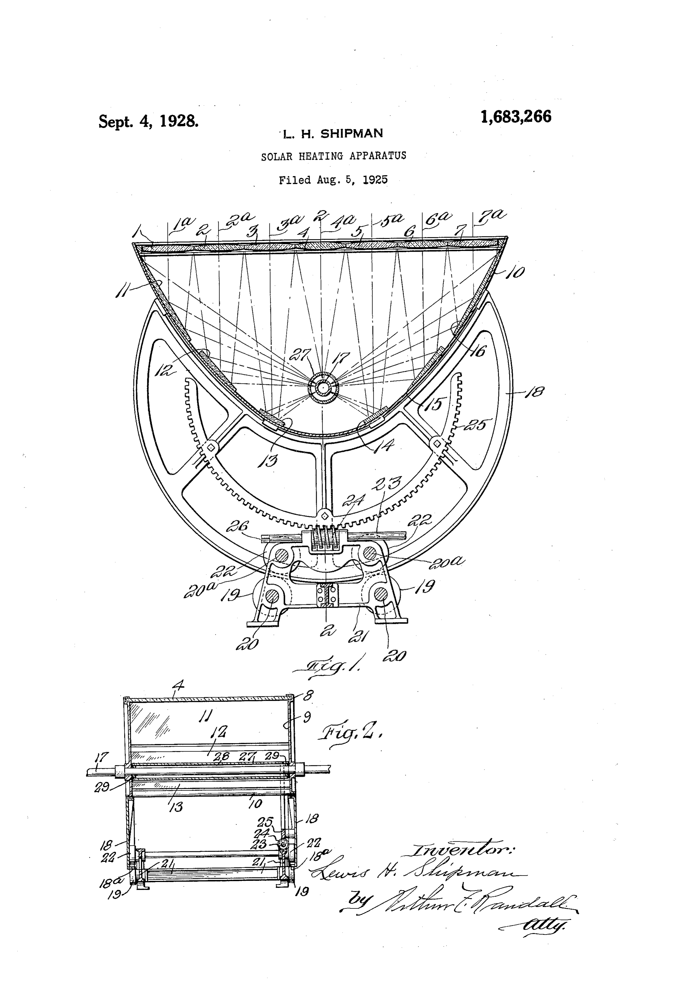
My invention relates to Solar heating ap from the line of incidence of this median line paratus and it has for its object to provide with its reflector to the pipe 17 being, in the an apparatus of this kind which will be of case of each of the six lenses, the same. simple and efficient construction. It Will be clear from the description given 60 5 To these ends I have provided a solar heat above that with the group of lenses disposed ing apparatus having the peculiar features perpendicularly to solar rays, those rays of construction and mode of operation set passing through each lens will be condensed forth in the following description, the novel and directed upon the reflectors, and thence features of the invention being particularly directed, still converging to a focal line at 85 O pointed out and defined in the claims at the the pipe 17. The middle lens 4 is constructed close thereof. So as to focus directly upon the pipe 17. It In the accompanying drawings: will thus be clear that if each lens collects Figure 1 is a transverse vertical sectional and delivers upon the pipe a given amount of view of a solar heating apparatus constructed heat, the total heat delivered to the pipe 17 70 5 in accordance with my invention. Will be with the number of lenses shown, Figure 2 is a section on line 2-2 of Fig Seven times that delivered by one lens. lure 1. The apparatus which have designed is in My improved solar heating apparatus com tended, for example, for household or do prises a plurality of focusing lenses 1 to 7 mestic use, and would be placed in a posi 2C) inclusive, preferably arranged in one plane. tion where it would be exposed to the sun's with their axes parallel. These lenses are in rays with the axis of the pipe 17 extending the form of bars as shown in Figure 2, and north and south.
are supported at their ends in channels 8, 8 In order that the group of lenses may be provided upon the inner faces of two mem maintained perpendicularly to the sun's rays, Y. SO ES bers 9,9. These two members 9 are the end provision is herein made for adjustment of walls of a trough-shaped frame 10, which for the trough frame 10 together with the mir convenience may be made of the parabolic rors and lenses on the axis of the pipe 17 to shape, in cross section, as shown in Figure 1, follow the movement of the sun during the said end wall members 9 being disposed with day. To provide for this, the trough frame 85 30 in the trough frame 10 and secured to the 10 has secured to each end thereof an arcu latter in any suitable manner. ate leg 18, whose curve is concentric with the Within the frame 10 are also fixedly axis of pipe 17, and these legs rest upon two mounted a number of reflectors 11, 12, 13. pairs of rollers 19, 19, fixed to the ends of 14, 15 and 16, one for each lens except the shafts 20 journaled in bearings on a frame 21. O centrally disposed lens 4. Each reflector is The peripheral portion of each leg 18 is in the form of a strip or bar extending from made with a flange 18 resting on the wheels end to end of the trough-shaped frame 10, 19 and said flange is held against tilting on and may be made of any suitable material or the wheels 19 by two pairs of rollers 22 dis materials. posed immediately above the flanges 18. Extending through the trough-shaped The frame 21 rotatably supports a shaft 23 5 frame 10 is a metal pipe 17, and this pipe be carrying a worm 24 engaging a segmental sides extending loosely through holes in the worm gear 25, the latter being bolted rigidly end walls 9, is positioned with its axis coin to one of the arcuate legs 18. As the sun cident with the focal line of the parabolic travels across the firmament during the day frame 10. It will thus be seen that the re the shaft 23 and Worm 24 are rotated in timed flectors 11-16 are disposed in a group relation therewith and act through the seg focused upon the pipe 17, and that the beams mental gear 25 to swing the legs 18, frame of light from all of the lenses except the 10 and parts carried by the latter on the axis middle lens 4 are, owing to this arrangement, of pipe 17 so as to maintain the plane of the 05 50 all of the same length or substantially the lenses perpendicular to the Sun's rays. This same length as measured from the lenses to rotation of the shaft 23 may be effected auto the mirrors and thence to the pipe. In Fig matically by suitable orientating means, or ure 1 the lines 1’, 2, 3, 4', etc., indicate the the same may be effected manually by means median planes of the lenses, and the distance of a socket crank applied to the squared end O 55 from each of the lenses, except the middle. 26 of the shaft 23. As will be clear, the worm lenses 4 to its reflector, plus the distance 24 through its engagement with the seg
Page 3
mental gear 25 serves to lock the rotatable or 17 would be connected with a supply of air adjustable parts against the effect of gravity or water, and the opposite end of the pipe 17 or accidental displacement. would deliver the steam or heated air to 30 In connection with the pipe 17 I have transforming or storage apparatus. shown a transparent glass jacket 27 having What 1. In
I claim is:
an apparatus for utilizing solar heat an interior diameter greater than the out side diameter of the pipe 17, so as to provide the combination of a parabolic reflecting a dead air space 28, which is closed at its structure comprising a plurality of flat lon ends by collars 29 by which the glass tube 27 gitudinally extending reflectors disposed 35 parallel with the focal axis of said struc 10 is separated from the pipe 17. It will be clear ture;
that the air contained within the tube 27 will ing lensa bars plurality of longitudinally extend disposed parallel with the focal become highly heated and its heat will be axis of said structure and supported in posi 40 transmitted to the pipe 17. - tion at the front of said structure so as to The above described apparatus is of simple - 15 and efficient construction, and while I have concentrate the rays on to said reflectors, and shown the apparatus as utilizing the collect a conduit whose axis is coincident with the ed energy from the sun to heat a pipe 17 and focal axis of said reflecting structure. the air within the tubular jacket 27, yet it will 2. An apparatus for utilizing Solar heat 45 be clear that other devices located at the focal constructed in accordance with claim 1 and 20. line or regions may be substituted therefor. wherein is provided a tubular member sur The construction described, however, is use and rounding said conduit within said structure ful for heating air or water contained with said providing an inclosed air space between tubular member and said conduit, said in the pipe 17, and the steam or heated air tubular member being transparent. may be utilized for various purposes, being 25 continuously supplied by my apparatus, it being understood that one end of the pipe LEWISH. SHIPMAN.
Provenance
- Collection
- Cited prior art
- Original PDF
- patentimages.storage.googleapis.com →
- Filed
- 1925-08-05
- Pages
- 3
- Method
- pdftotext (the PDF's own text layer) + pdftoppm 300dpi page scans
- Source
- Google Patents bibliographic record
- Granted
- 1928-09-04
- Inventors
- Lewis H Shipman
- Transcribed from
- patentimages.storage.googleapis.com →