patent · US4081289
Solar energy system
28 March 1978
Page 1 — bibliographic record
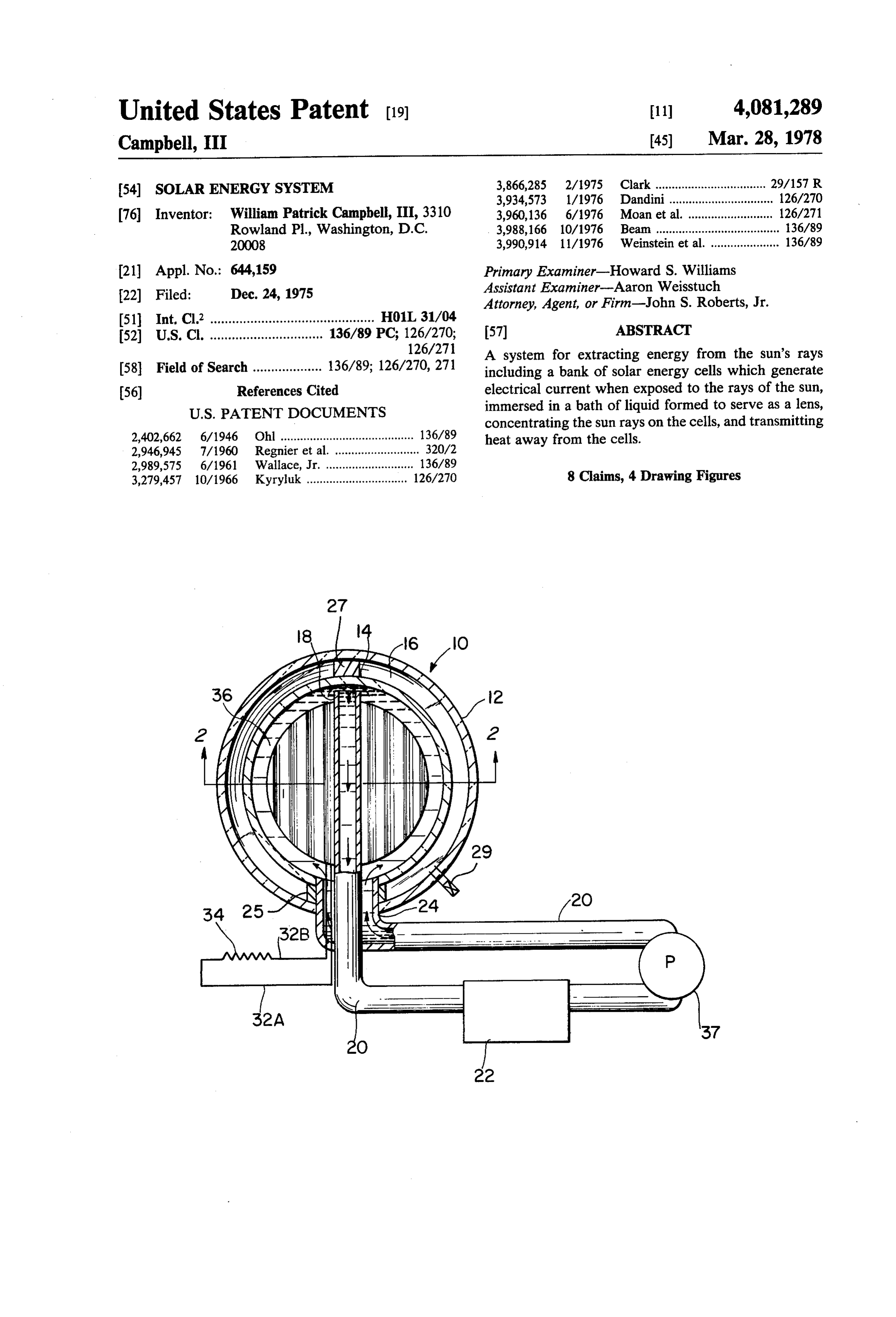
United States Patent (19) 11) 4,081,289 Campbell, III 45) Mar. 28, 1978 3,866,285 2/1975 Clark .................................. 29/157 R (54) SOLAR ENERGY SYSTEM 3,934,573 1/1976 Dandini................................ 126/270 76) Inventor: William Patrick Campbell, III, 3310 3,960,136 6/1976 Moan et al. .......................... 126/271 Rowland Pl., Washington, D.C. 3,988,166 10/1976 Beam ...................................... 136/89 20008 3,990,914 11/1976 Weinstein et al. ..................... 136/89
(21) Appl. No.: 644,159 Primary Examiner-Howard S. Williams Assistant Examiner-Aaron Weisstuch 22) Filed: Dec. 24, 1975 Attorney, Agent, or Firm-John S. Roberts, Jr. 51 Int, Cl’............................................. H01L 31/04 ABSTRACT (52) U.S. C. ............................... 136/89 PC; 126/270; 57 126/271 A system for extracting energy from the sun's rays (58) Field of Search ................... 136/89; 126/270, 271 including a bank of solar energy cells which generate (56) References Cited electrical current when exposed to the rays of the sun,
concentrating the sun rays on the cells, and transmitting 2,402,662 6/1946. Ohl ................. ... 136/89 heat away from the cells.
2,946,945 7/1960 Regnier et al. .......................... 320/2 2,989,575 6/1961 Wallace, Jr. ........................... 136/89 3,279,457 10/1966 Kyryluk ............................... 126/270 8 Claims, 4 Drawing Figures
Page 2
Drawing sheet — no readable text.
Page 3
SOLAR ENERGY SYSTEM SUMMARY OF THE INVENTION
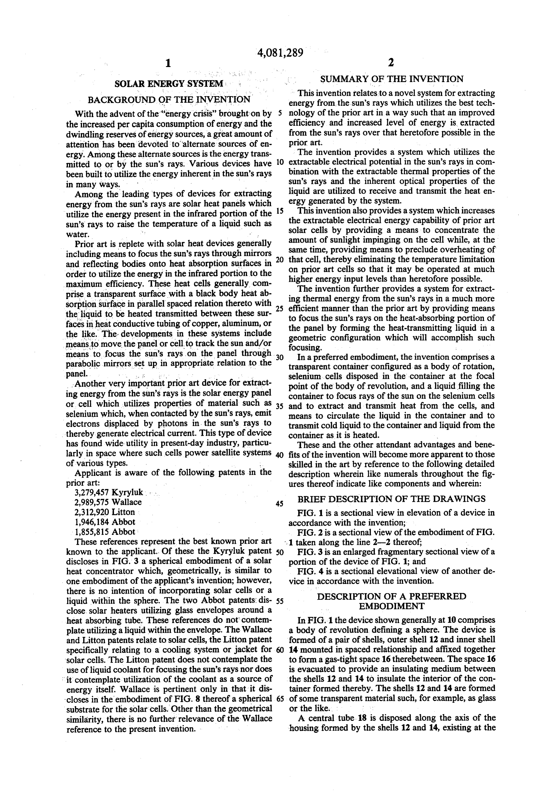
This invention relates to a novel system for extracting
BACKGROUND OF THE INVENTION energy from the sun's rays which utilizes the best tech With the advent of the "energy crisis” brought on by 5 nology of the prior art in a way such that an improved the increased per capita consumption of energy and the efficiency and increased level of energy is extracted dwindling reserves of energy sources, a great amount of from the sun's rays over that heretofore possible in the prior art.
attention has been devoted to alternate sources of en ergy. Among these alternate sources is the energy trans 10 The invention provides a system which utilizes the mitted to or by the sun's rays. Various devices have extractable electrical potential in the sun's rays in com been built to utilize the energy inherent in the sun's rays bination with the extractable thermal properties of the sun's rays and the inherent optical properties of the in many ways.
Among the leading types of devices for extracting ergy liquid are utilized to receive and transmit the heat en energy from the sun's rays are solar heat panels which generated by the system.
utilize the energy present in the infrared portion of the 15 theThis invention also provides a system which increases extractable electrical energy capability of prior art sun's rays to raise the temperature of a liquid such as solar cells by providing a means to concentrate the
Prior art is replete with solar heat devices generally amount of sunlight impinging on the cell while, at the including means to focus the sun's rays through mirrors same time, providing means to preclude overheating of that cell, thereby eliminating the temperature limitation and reflecting bodies onto heat absorption surfaces in on prior art cells so that it may be operated at much order to utilize the energy in the infrared portion to the higher energy input levels than heretofore possible. maximum efficiency. These heat cells generally com prise a transparent surface with a black body heat ab ing thermal energyfurther
The invention provides a system for extract sorption surface in parallel spaced relation thereto with 25 efficient manner than thethe from sun's rays in a much more prior art by providing means the liquid to be heated transmitted between these sur to focus the sun's rays on the heat-absorbing portion of faces in heat conductive tubing of copper, aluminum, or the panel by forming the heat-transmitting liquid in a the like. The developments in these systems include geometric configuration which will accomplish such means to move the panel or cell to track the sun and/or means to focus the sun's rays on the panel through 30 focusing. In a preferred embodiment, the invention comprises a parabolic mirrors set up in appropriate relation to the transparent container configured as a body of rotation, panel. - ... : : selenium cells disposed in the container at the focal Another very important prior art device for extract point of the body of revolution, and a liquid filling the ing energy from the sun's rays is the solar energy panel container to focus rays of the sun on the selenium cells or cell which utilizes properties of material such as 35 and to extract and transmit heat from the cells, and selenium which, when contacted by the sun's rays, emit means to circulate the liquid in the container and to electrons displaced by photons in the sun's rays to transmit cold liquid to the container and liquid from the thereby generate electrical current. This type of device container as it is heated.
has found wide utility in present-day industry, particu These and the other attendant advantages and bene larly in space where such cells power satellite systems fits of the invention will become more apparent to those of various types. skilled in the art by reference to the following detailed Applicant is aware of the following patents in the description wherein like numerals throughout the fig prior art: ures thereof indicate like components and wherein: 3,279,457 Kyryluk, BRIEF DESCRIPTION OF THE DRAWINGS
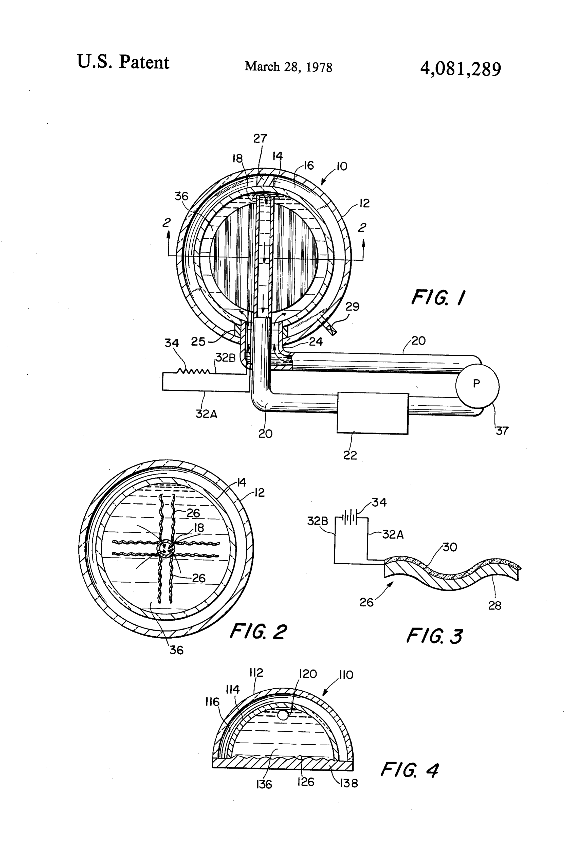
2,312,920 Litton FIG. 1 is a sectional view in elevation of a device in 1,946,184 Abbot accordance with the invention; 1,855,815 Abbot; FIG. 2 is a sectional view of the embodiment of FIG. These references represent the best known prior art .1 taken along the line 2-2 thereof;
known to the applicant. Of these the Kyryluk patent 50 FIG. 3 is an enlarged fragmentary sectional view of a discloses in FIG.3 a spherical embodiment of a solar portion of the device of FIG. 1; and heat concentrator which, geometrically, is similar to FIG. 4 is a sectional elevational view of another de one embodiment of the applicant's invention; however, vice in accordance with the invention. there is no intention of incorporating solar cells or a DESCRIPTION OF A PREFERRED liquid within the sphere. The two Abbot patents: dis 55 EMBODIMENT close solar heaters utilizing glass envelopes around a heat absorbing tube. These references do not contem In FIG.1 the device shown generally at 10 comprises plate utilizing a liquid within the envelope. The Wallace a body of revolution defining a sphere. The device is and Litton patents relate to solar cells, the Litton patent formed of a pair of shells, outer shell 12 and inner shell specifically relating to a cooling system or jacket for 60 14 mounted in spaced relationship and affixed together solar cells. The Litton patent does not contemplate the to form a gas-tight space 16therebetween. The space 16 use of liquid coolant for focusing the sun's rays nor does is evacuated to provide an insulating medium between : it contemplate utilization of the coolant as a source of the shells 12 and 14 to insulate the interior of the con energy itself. Wallace is pertinent only in that it dis tainer formed thereby. The shells 12 and 14 are formed closes in the embodiment of FIG. 8 thereof a spherical 65 of some transparent material such, for example, as glass substrate for the solar cells. Other than the geometrical or the like.
similarity, there is no further relevance of the Wallace A central tube 18 is disposed along the axis of the reference to the present invention. housing formed by the shells 12 and 14, existing at the
Page 4
bottom end thereof and connecting with a conduit 20 Another important feature of the embodiment of connected to some load 22 such as a heater, heat ex FIGS. 1 and 2 is that the spherical configuration can be changer, or storage device. The conduit 20 then returns mounted through the roof of a building in such a way as to the device 10 entering the housing formed by the to function as a skylight, providing a portion of the shells 12 and 14 in an inlet manifold 24 concentrically concentrated light to the interior of a building on which disposed with respect to the tube 18. As is best seen in it is mounted. . .. . . . FIG. 2, a series of corregated panels 26 are mounted on In FIG. 4, another embodiment incorporating the the tube 18 extending radially therefrom toward the features of this invention is illustrated. In this embodi inner shell 14. The panels 26 are semicircular in configu ment components thereof corresponding to like compo ration and are sized to conform closely in spaced rela 10 nents of the embodiments of FIGS. 1-3 are indicated by tionship to the inner surface of the shell 14. like numerals only of the next higher order. In this As is best seen in FIG. 3, the panels indicated gener embodiment, the body of revolution comprises a semi ally there at 26 are composed of a corrugated substrate cylindrical housing formed of an outer shell 112 and an 28 of some suitable material such, for example, as alumi inner shell 114 comprising a transparent material with a num, plastic, glass, or the like. Superimposed on the 15 sealed space 116 therebetween, which space is evacu substrate 28 are solar cells 30 composed of a suitable ated to form an insulating vacuum as in the embodiment material which will generate electricity when exposed of the preceding figures.
to the rays of the sun such, for example, as selenium, Within the housing formed by the shells 114 and 112, silicon, or the like, as is well known in the art of solar and forming a bottom surface thereto, is a solar panel cell fabrication. The cell 30 is preferably composed of a 20 126 formed, as in the preceding embodiment, on a sub single crystal extruded in corregated sheet form and strate of corregated material as was shown specifically adhered to the substrate 28 with adhesive or the like. in FG, 3.
Electrical leads 32A and 32B are connected to the cell The interior of the housing formed by the inner and 30 and to an electrical load 34 such, for example, as a outer shells 114 and 112 is filled with a liquid 136 which, storage battery or the like. 25 as in the preceding embodiment, preferably is water or Referring again to FIG. 1, it can be seen that the leads the like. Inlet and outlet connections are provided at the 32A and 32B are disposed proximate to the tube 18 to lower and upper areas of the housing, respectively, to exit from the device 10 for connection to the load 34. provide for circulation of the liquid 136 through the The leads 32A and 32B are preferably connected housing. A lower inlet (not shown) and an upper inlet through the medium of a bus or collector from each of 30 120 are preferably provided in opposite ends of the the panels 26 as is well known in the electrical art. housing formed by the shells 112 and 114. An insulating Structural details of the device include an annular material 138 such, for example, as urethane foam or the support 25 between the bottom of the shells and a sup like is disposed beneath the panel 126 to provide com port 27 between the tops of the shells to transfer loads 35 plete insulation for the device 110. between the sheels and increase the structural efficiency The device of the embodiment of FIG. 4 functions in of the device. Evacuation of the space between the substantially the same manner as that described for the shells may be accomplished through valved conduit 29 embodiment of the preceding figures. The sun's rays and may be repeated if need be due to opening of the penetrate the transparent shells 112 and 114 and are device. focused by the liquid 136 within the inner shell 114 to . With the aforedescribed structure complete, the inte concentrate on the solar panel 126, whereby electrical rior of the housing formed by the inner shells 14 is filled and thermal energy is produced and transmitted from with a suitable transparent liquid 36 such, for example, the housing in a manner identical to that of the embodi as Water. ments described in FIGS. 1-3. Pump means 37 are provided in the conduit 20 to As can be seen from the aforegoing description, the circulate the liquid 36 from the tube 18 to the manifold 45 invention provides a combined solar electrical and solar 24. thermal generating system utilizing a liquid for focusing In operation, the device is exposed to the rays of the the sun's rays, cooling the electrical generating panels, sun. The rays of the sun penetrate the transparent shells and for transmitting the thermal heat generated from 12 and 14 and are focused by the liquid 36 within the the system. . - ; inner shell onto the solar panels 26, whereupon electri What has been set forth above is intended primarily as cal energy is generated by the impinging sun's rays and exemplary of a teaching in accordance with the inven is extracted from the device 10 through the leads 32A tion to aid those skilled in the art in the practice thereof. and 32B to the load 34. The sun's rays impinging on the What is new and desired to be protected by Letters solar panels also raise the temperature thereof, thereby Patent of the United States is:
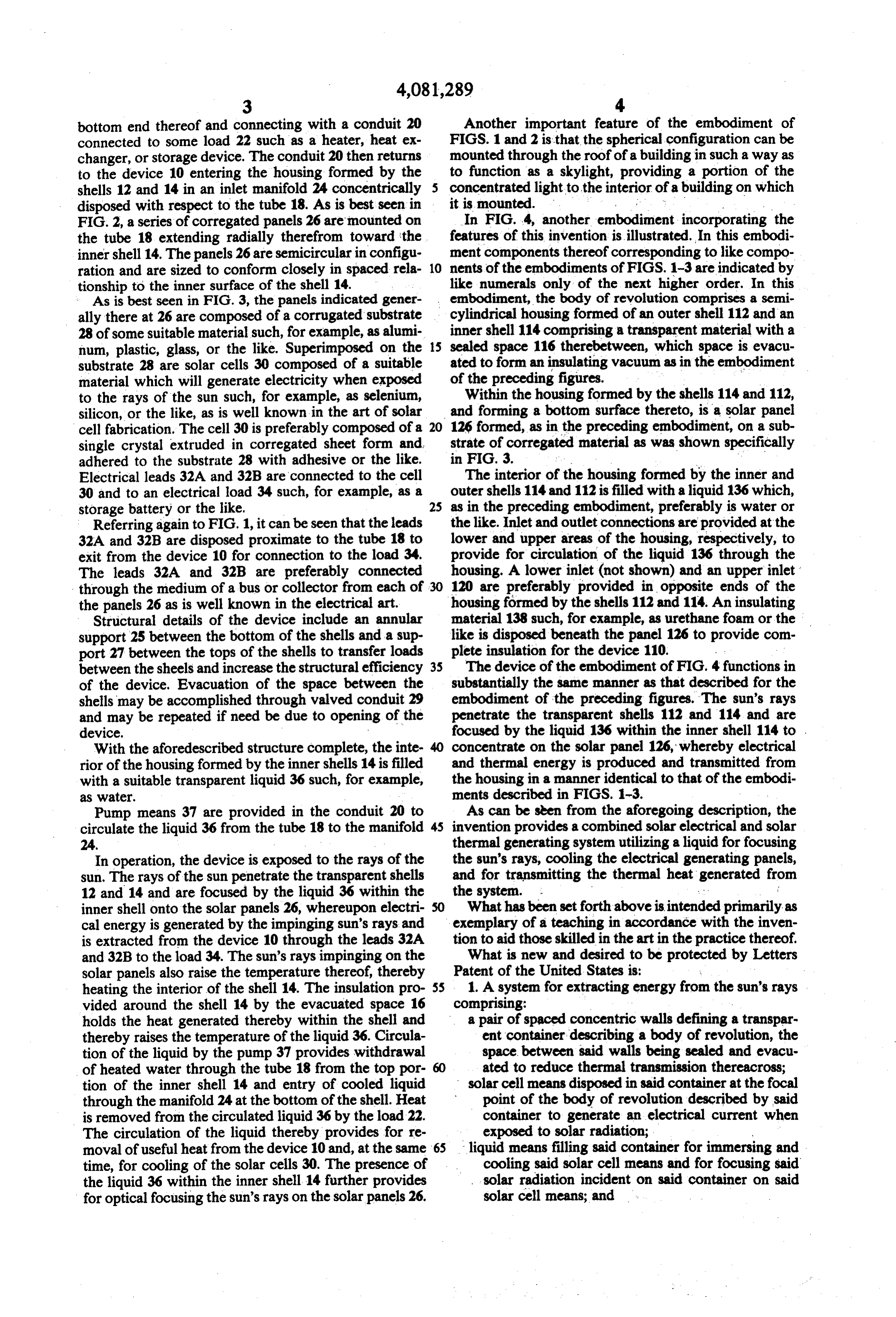
heating the interior of the shell 14. The insulation pro 55 1. A system for extracting energy from the sun's rays vided around the shell 14 by the evacuated space 16 comprising:
holds the heat generated thereby within the shell and a pair of spaced concentric walls defining a transpar thereby raises the temperature of the liquid 36. Circula ent container describing a body of revolution, the tion of the liquid by the pump 37 provides withdrawal space between said walls being sealed and evacu of heated water through the tube 18 from the top por ated to reduce thermal transmission thereacross; tion of the inner shell 14 and entry of cooled liquid solar cell means disposed in said container at the focal through the manifold 24 at the bottom of the shell. Heat point of the body of revolution described by said is removed from the circulated liquid 36 by the load 22. container to generate an electrical current when The circulation of the liquid thereby provides for re exposed to solar radiation; moval of useful heat from the device 10 and, at the same liquid means filling said container for immersing and time, for cooling of the solar cells 30. The presence of cooling said solar cell means and for focusing said the liquid 36 within the inner shell 14 further provides solar radiation incident on said container on said for optical focusing the sun's rays on the solar panels 26. solar cell means; and
Page 5
circulation means for transmitting cooled liquid to 4. The system in accordance with claim 1 wherein said solar cell means comprises at least one solar cell said container, for circulating liquid in said con adhered to a substrate.
tainer, and for transmitting heated liquid from said 5. The system in accordance with claim 4 wherein container. said substrate is corrugated.
2. The device in accordance with claim 1 wherein 6. The system in accordance with claim 1 wherein said solar cell means comprises pairs of solar cells said body of revolution comprises a sphere and wherein mounted in parallel, coextensive spaced relationship to said walls comprise concentric spherical walls. one another.
3. The system in accordance with claim 1 wherein 10 7. The system in accordance with claim 6 further comprising a central outlet tube for said liquid means said body of revolution describes a semicylindrical communicative housing and wherein said walls comprise a pair of semi said container. with and extending into the interior of cylindrical walls, planar walls closing the ends of the 8. The system in accordance with claim 7 wherein semicylindrical body, said means for generating electri 15 said pairs of solar cells are mounted to radiate out cal current comprising the remaining wall of the semi wardly from said outlet tube and wherein said tube is substantially vertical and enters said container from the cylindrical container and insulating means behind said bottom such that said liquid rises as it is warmed to be means to complete the insulating enclosure for said transmitted from said container.k system. 20
Provenance
- Collection
- Cited prior art
- Original PDF
- patentimages.storage.googleapis.com →
- Filed
- 1975-12-24
- Pages
- 5
- Method
- pdftotext (the PDF's own text layer) + pdftoppm 300dpi page scans
- Source
- Google Patents bibliographic record
- Granted
- 1978-03-28
- Inventors
- William Patrick Campbell, III
- Transcribed from
- patentimages.storage.googleapis.com →