patent · US4134392
Solar energy collection
16 January 1979
Page 1
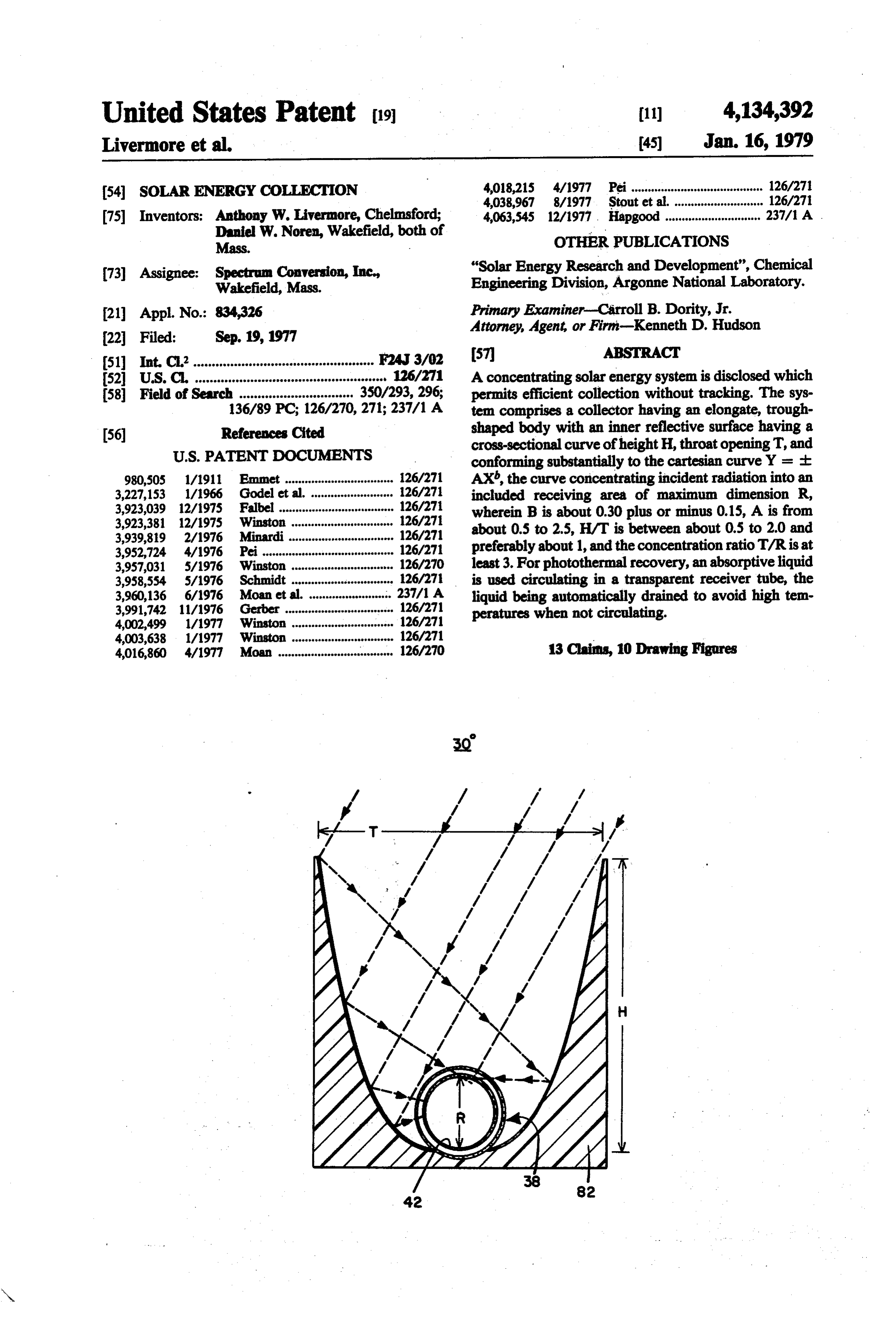
United States Patent (19) (11) 4,134,392 Livermore et al. 45) Jan. 16, 1979 54 SOLAR ENERGY COLLECTION 4,018,215 4/1977 Pei ........................................ 126/27 4,038967 8/1977 Stout et al............................ 126/27 75) Inventors: Anthony W. Livermore, Chelmsford; 4,063,545 12/1977. Hapgood ............................. 237/1 A Daniel W. Noren, Wakefield, both of OTHER PUBLICATIONS
Mass.
73) Assignee: Spectrum Conversion, Inc., "Solar Energy Research and Development', Chemical Wakefield, Mass. Engineering Division, Argonne National Laboratory. (21) Appl. No.: 834,326 Primary Examiner-Carroll B. Dority, Jr. Attorney, Agent, or Firm-Kenneth D. Hudson
51) Int. C.’................................................. F24J 3/02 57 ABSTRACT 52 U.S. C. ............................................. 126/271 A concentrating solar energy system is disclosed which 58) Field of Search ............................... 350/293,296; permits efficient collection without tracking. The sys 136/89 PC; 126/270,271; 237/1 A tem comprises a collector having an elongate, trough (56) References Cited shaped body with an inner reflective surface having a
cross-sectional curve of height H, throat opening T, and conforming substantially to the cartesian curve Y = - 980,505 1/1911 Emmet ................................. 126/271 AX, the curve concentrating incident radiation into an 3,227,153 1/1966 Godel et al. ......................... 26/271 included receiving area of maximum dimension R, 3,923,039 12/1975 Fallbel ... ... 126/27 wherein B is about 0.30 plus or minus 0.15, A is from 3,923,381 12/1975 Winston 126/27 about 0.5 to 2.5, H/T is between about 0.5 to 2.0 and 3,939,819 2/1976 Minardi ... 126/271 3,952,724 4/1976 Pei......... ... 126/271 preferably about 1, and the concentration ratio T/R is at 3,957,031 5/1976 Winston .............................. 126/270 least 3. For photothermal recovery, an absorptive liquid 3,958,554 5/1976 Schmidt ............................... 126/271 is used circulating in a transparent receiver tube, the 3,960,136 6/1976 Moan et al. ... ... 237/1 A liquid being automatically drained to avoid high tem 3,991,742 11/1976 Gerber ................................. 126/271 peratures when not circulating. 4,002,499 1/1977 Winston ............................... 126/271 4003,638 1/1977 Winston ............................... 126/271 4,016,860 4/1977 Moan ................................. 126/270 13 Clains, 10 Drawing Figures
Page 2
Drawing sheet — no readable text.
Page 3
Drawing sheet — no readable text.
Page 4
Drawing sheet — no readable text.
Page 5
throat opening T, and concentrating incident radiant soLAR ENERGY COLLECTION energy into an included receiver area of maximum di mension R, wherein X is positive, b is about 0.3 plus or
BACKGROUND OF THE INVENTION minus 0.15, A is about 0.5 to 2.5, the ratio of H to T is This invention relates to electromagnetic energy col 5 between about 0.5 to 2.0 and preferably about 1, and the lection and more particularly to devices and systems for concentration ratio T/R is at least 3. Preferably the the collection and recovery of solar energy or the like. receiver area of energy concentration within the cross Solar energy is an increasingly important source of section is a circle substantially in peripheral contact energy for space heating and cooling, process heat, with the vertex of the curve and an elongate absorbing electrical generation and the like. Relatively low tem 10 means for radiation is located in the collector at the peratures are useful for space heating, but cooling and receiver area.
process applications generally require higher tempera The preferred collector according to the first aspect tures. Direct photovoltaic conversion to electricity is of the present invention concentrates about 99% of the known but existing photovoltaic materials such as sili rays incident within an acceptance angle of 60 where A cone wafer materials are currently expensive. Since 15 in the above formula equals about 1.75, b equals about solar insolation per unit of area is low, high efficiency 0.3, each of H and T are about 6 inches and R is the and concentration are desirable. diameter of a circle at about 1.5 inches, providing a Most of the solar energy collectors heretofore em concentration ratio of about 4.
ployed have been flat plate collectors without concen According to a second aspect of the present inven tration. While simple, such systems are limited in effi tion, a radiation absorbing liquid is circulated through a ciency and in the temperatures obtainable. Focusing transparent conduit located at a collector receiver area, collectors, that is those which concentrate solar energy the liquid being utilized both to photothermally absorb by forming an image of the sun, are known and are and transport the incident energy from the collector to capable of very high temperatures. However they can a recovery system for storage or use. A pump or other utilize only direct beam rays and require continuous 25 suitable activatable means are provided to circulate the tracking of the daily and seasonal solar movement. liquid through the conduit and means are provided for They cannot collect diffuse, scattered sunlight. draining the liquid from the conduit when the pump is Improved nonfocusing concentrating collectors have not operating. Preferably, the conduit is inclined to the been recently disclosed in U.S. Pat. No. 3,923,381 and horizontal with an outlet substantially at its lowest further described in an article entitled: "Solar Energy 30 point, and the draining means comprises a reservoir Research and Development' published by the Argonne below the conduit outlet. By thus employing an absorp National Laboratory, dated June 19, 1976. Those refer tive liquid both for energy absorption and transport, ences contain a good description of the different types and providing for its automatic drainage from the col of collectors and the advantages and applications for lectors when the liquid is not circulating, energy ab each. However, the nonfocusing collectors described 35 sorption automatically terminates to avoid dangerous have decreasing acceptance angles with increasing con temperature buildup. Incident energy to the collector, centration and require means for repositioning monthly in the absence of absorbing liquid, is re-radiated without or seasonally for concentration ratios greater than about substantial absorption or temperature increase. 2. In a third aspect, the present invention provides a There is a continuing need in the solar energy field 40 novel receiver tube for circulation and automatic drain for a concentrating collector system which provides a age of a radiation absorptive liquid within a concentrat concentration ratio of 3 to 6 or more and which is effi ing collector, the tube being of material substantially cient at a sufficiently wide angle of incidence to permit transparent to and non-absorptive of said radiation and use as a totally stationary collector. Moreover, with comprising an outer evacuated envelope and an inner concentrating collectors capable of achieving substan 45 elongate chamber which is sealed at one end and has tially elevated temperatures, means are needed to pre inlet and outlet means at the other end, one being lo vent the buildup of dangerously elevated temperatures cated at the lowermost position in said chamber, the and pressures when the heat is not needed or the cool inner chamber being divided into one portion for trans ing system is inoperative. porting said liquid from said inlet to said sealed end and Accordingly, principal objects of the present inven a second portion for returning the liquid from the sealed tion include provision of nonfocusing radiant energy end to said outlet. Preferably alongitudinal separator of collector systems and devices which are efficient at a transparent or reflecting material is positioned within sufficiently wide incident angle to be useful at concen the inner chamber to divide it into the said two portions. tration ratios of three or more as a stationary system, DESCRIPTION OF THE PREFERRED which minimize loss of absorbed energy, and which 55 EMBODIMENTS provide a simple and convenient means for controlling temperature. In the accompanying drawings
SUMMARY OF THE INVENTION
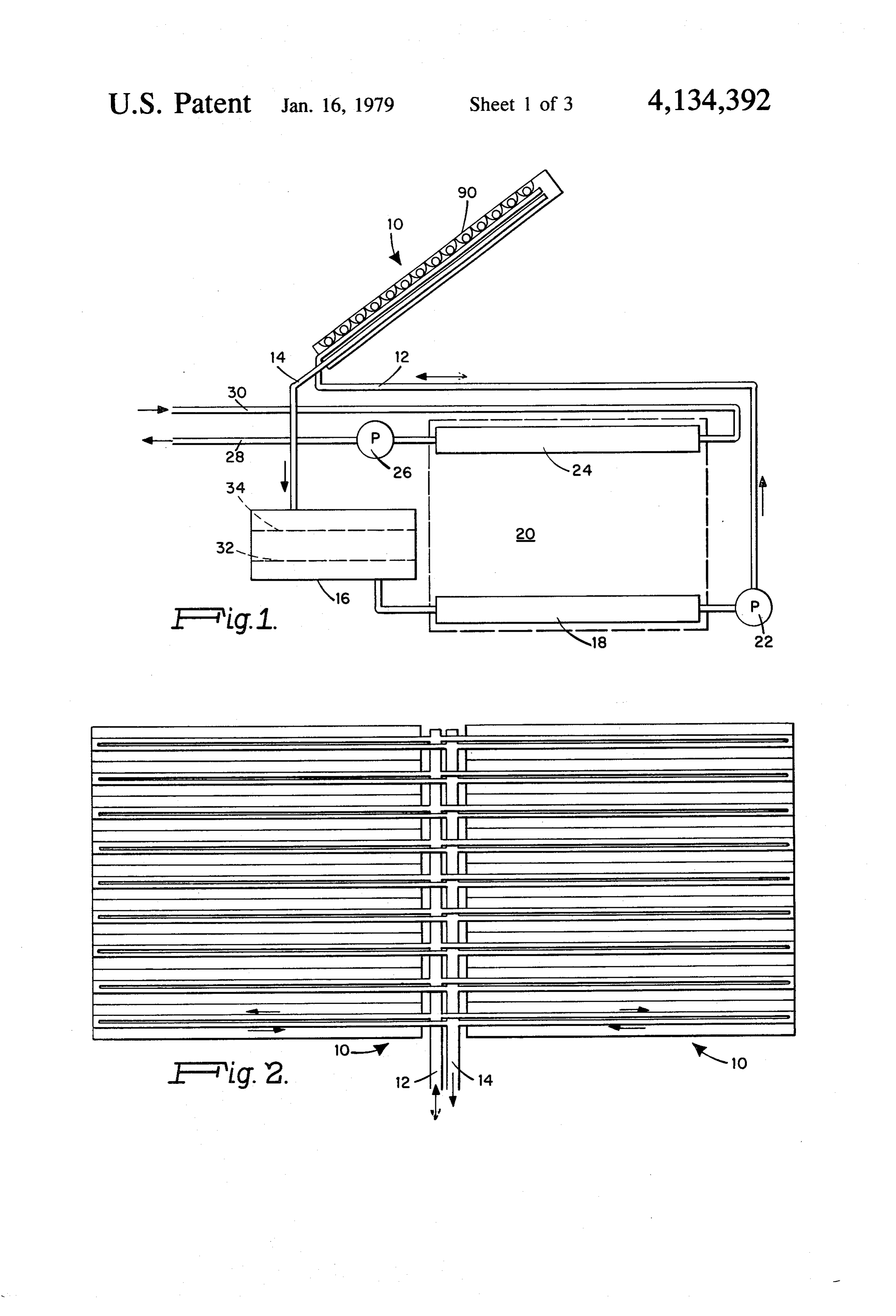
FIG. 1 is a schematic elevation of a solar heating system according to the present invention;
According to one aspect of the present invention, an FIG. 2 is a plan view of an array of solar collectors as efficient nonfocusing collector is provided with a con shown in FIG. 1;
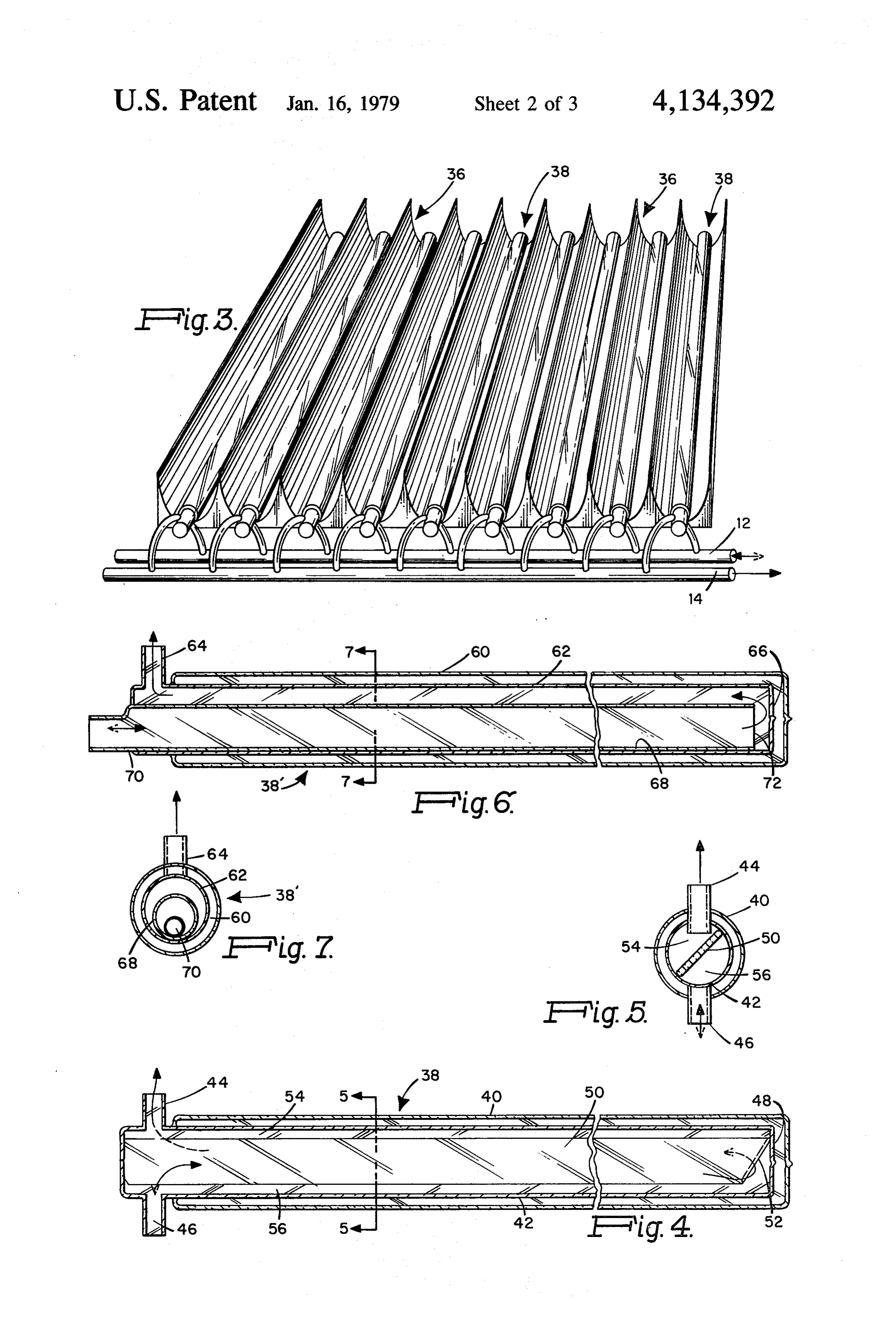
centration ratio of 3 or more and with a high efficiency FIG. 3 is a perspective view of one of the collector at a wide incidence angle of at least 40, and typically arrays illustrated in FIG. 2;
about 60', such that no solar tracking is required. The FIG. 4 is alongitudinal section through the preferred collector is an elongate trough-shaped member having receiver tube within the collectors as shown in FIG. 3; an inner reflective surface with a substantially uniform FIG. 5 is a section along the line 5-5 of FIG. 4; cross-section, the cross-section substantially conform FIG. 6 is alongitudinal section through an alternative ing to the curve Y = - AX, having a height H, a receiver tube;
Page 6
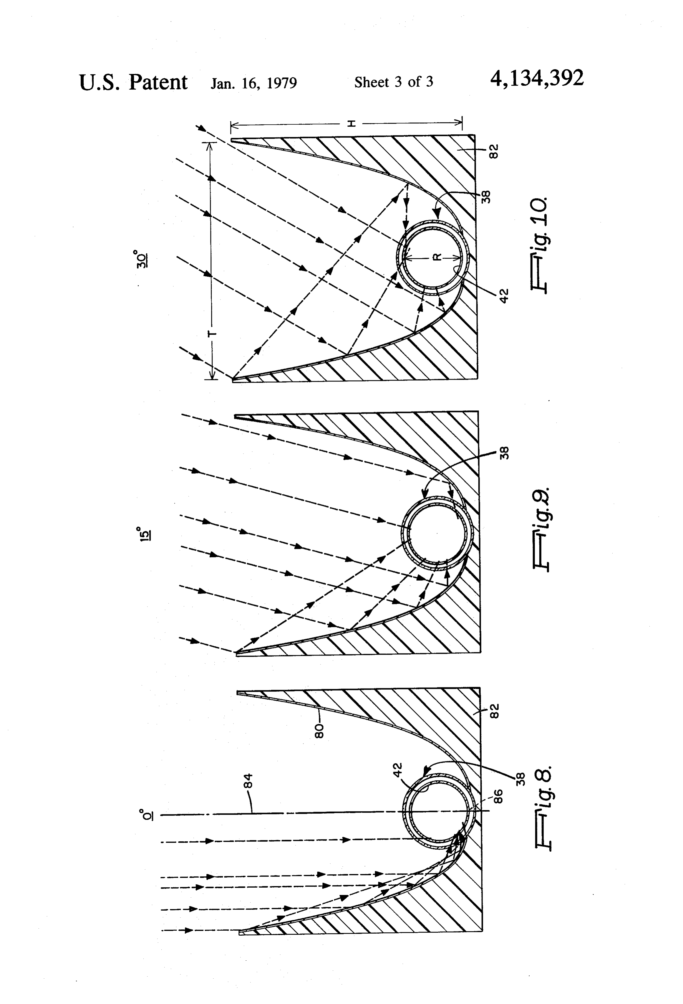
FIG. 7 is a section along the line 7-7 of FIG. 6; and, comprises a liquid which is substantially absorptive of FIGS. 8-10 are transverse cross-sections through solar radiation and which serves both to absorb the one of the identical collectors shown in FIG.3 showing incident sunlight, and to transport the resulting heat to reflection of incident incoming rays at various incident reservoir 20. Divider 50 is likewise of material which is angles. non-sorbent to sunlight and is preferably transparent but Referring to FIG. 1, a solar system according to the may be reflective rather than transparent since it is present invention is illustrated which comprises an immersed in the liquid. By thus employing a single array 10 of solar collectors exposed to sunlight, for liquid as both the sorber and transporter of the radiant example in fixed position on the roof of a building and energy, in a transparent tube, the temperature can be tilted to the southern horizon, an inlet conduit 12 deliv 10 controlled by flow rate when the pump 22 is operating ering liquid to the collectors, an outlet pipe 14 receiving and by automatic gravity drainage when the pump is photothermally heated liquid from the collectors, a not operating. With a concentrating collector as herein reservoir 16, a heat exchange 18 in tank 20, and a pump described, temperatures in excess of 500" F. are possible 22 for circulating fluid through conduit 12 to collector and such automatic control of the system is a desirable array 10. Tank 20 is filled with water or the like for 15 safety feature. Moreover, in a system sized to provide a storing heat which is extracted by heat exchanger 24 substantial amount of the desired energy in winter, ex and circulated by means of pump 26 to and from radia cess energy may be available in the summer and it may tors or the like (not shown) for utilizing the heat via be necessary to operate the system intermittently under pipes 28 and 30 respectively. When the pump 22 is the control of a thermostat. The terms transparent, operating to fill conduit 12, collector array 10 and con 20 reflective, sorptive and nonsorptive are used herein in duit 14 with liquid, the liquid level within reservoir 16 is the conventional sense used in solar energy collection illustrated at 32 and provides an air space thereover. and refer to those portions of the solar spectrum useful When the pump 22 is not operating, the liquid drains for photothermal or photovoltaic conversion, princi from the collector array 10 into the reservoir 16, filling pally visible wavelengths.
it to the level indicated at 34. 25 Any suitable liquid can be employed which is highly As illustrated in FIG. 3, the collector array 10 com absorptive of sunlight. Water or water-antifreeze mix prises a plurality of reflective collectors 36 which are tures commonly employed are too transparent but can trough-shaped as more fully hereinafter described and be made absorptive by addition of sorptive material which have at their base receiver tubes 38. The pre therein, for example black soluble dyes. A 50-50% mix ferred receiver tube is shown in FIGS. 4 and 5 and ture by volume of water and ethylene glycol to which comprises an outer evacuated envelope 40 and an inner about three ounces per gallon of a black aniline dye has chamber 42 having inlet 46 communicating with inlet been added is suitable and preferred. It has a reflective conduit 12 and outlet 44 communicating with outlet densitometer reading of 378, compared to 170 for flat conduit 14. Chamber 42 is sealed at end 48 and both black paint and 200 for black velvet, Densitometer read inlet 46 and outlet 44 are located at the opposite end 35 ings of at least 200, and as high as practical are pre thereof, inlet 46 being located at its lowermost position ferred, to drain liquid from the chamber. Extending longitudi An alternative receiver tube is shown in FGS. 6 and nally within the chamber 42 and across its diameter is a 7 which comprises an outer evacuated envelope 60, and divider or separator 50 having a notched end 52 for an inner chamber comprising tube 62 communicating passage of liquid and which divides chamber 42 into an with outlet 64 and having a closed end 66, and an inner inlet portion 56 through which liquid flows from inlet most tube 68 communicating with inlet 70 and having 46 to end 48 and an outlet portion 54 through which the opposite end 72 terminating short of end 66 to allow liquid returns from the end 48 to outlet 44. liquid to flow from within the tube 68 outwardly As shown, liquid circulated by pump 22 flows through the tube 62. Tube 68 rests on the bottom inte through inlet 46 to outlet 44. When pump 22 is turned 45 rior wall of tube 62 and inlet 70 is at its lowermost point, off or fails, the liquid flow reverses, draining back again to provide substantially complete drainage of heat through inlet 46, conduit 12 and pump 22 to reservoir sorptive liquid by gravity when the circulating pump is 16. If desired, inlet 46 and outlet 44 may be reversed, not operating. Envelope 60 and tube 62 are of transpar with drainage directly through conduit 14 to reservoir ent material. Tube 68 is also preferably transparent but 16. However reversing flow as shown is preferred to may be reflective and opaque if desired. minimize cavitation during circulation. Divider 50 pref As shown in FIG. 3, the reflective trough-shaped erably fits loosely, or is notched, adjacent inlet 46 to collectors 36 are elongate and have a uniform transverse allow complete drainage of liquid from chamber 42. As cross-section illustrated in FIGS. 8-10. The collectors shown in FIG. 5, outlet tube 44, preferably extends into have an inner reflective surface 80 which can comprise chamber 42 to prevent complete rotation of divider 50. 55 polished metal but which is preferably, as shown, a Preferably, as schematically shown in FIG. 2, two metallized layer on the inner surface of foam plastic 82. arrays of collectors 36 are disposed around conduits 12 The transverse section of surface 80 substantially con and 14 and the receiver tubes 38 are tilted to the hori forms to a curve of the equation Y = t AX, having zontal such that the end having inlet 46 is below the two half curves symmetrical about an axis of symmetry sealed end 48 so that fluid flowing through chamber 42 60 84 which is the positive X axis and which intersects the will substantially drain by gravity to reservoir 16. Each lower edge of surface 80 at the curve vertex 86. As array can be molded as a unit as more fully described shown in FIG. 10, the curve has a height “H”, a throat hereinafter. opening 'T', and concentrates incident radiation into a The envelope 40 and walls of chamber 42 of receiver circular receiver area of diameter R, the diameter of tubes 38 comprise a material such as glass or plastic 65 inner chamber 42 of receiver tube 38. which is substantially transparent to sunlight and do not FIGS. 8-10 illustrate ray traces for incident radiation substantially absorb sunlight or become significantly parallel to the axis of symmetry 84 (FIG. 8), at an angle heated thereby. The liquid circulating through the tubes 15thereto (FIG.9), and at 30 thereto (FIG.10). These
Page 7
figures illustrate that rays incident to the collector 36 at acceptance angle (d. 30' from the axis of symmetry) an angle from 0 to 30 in either direction from axis 84 being collected within the receiver area with no more either fall directly onto the receiver tube 38 or pass than three reflections. The peak instantaneous heat out thereto with a minimum number of reflections, not put is estimated to be 305 BTU/square foot per hour, more than five, and preferably not more than three. 5 with an average output per 6 hour day in March at 40 Thus the collectors illustrated concentrate most inci north latitude of about 200 BTU/square foot/hour, the dent rays within an acceptance angle of at least 60', an collector concentrating both direct beam and scattered angle sufficiently large to permit them to be fixed in radiation. All rays falling onto either side of the reflec stationary position and absorb a high proportion of the tor surface 80 from within the 60' angle pass to the incident radiation within that angle despite seasonal O receiver chamber 42.
variation in solar elevation. Preferably, the longitudinal The preferred collectors described above can pro axis of the collectors extends east to west and the axis of duce temperatures in excess of 500 F, the output tem symmetry 84 extends southward at an angle between perature being controlled by the circulating flow rate of the seasonal solstices. Collectors 36 are relatively long, absorbing liquid therethrough. They can be mounted in for example eight feet, and have closed reflective ends 15 fixed position on any desired surface and suitably ori (not shown) and receive and absorb energy from the ented to collect energy throughout the year. For daily solar movement without tracking. As indicated at mounting to a supporting surface which is not inclined 90 in FIG. 1, the upper surfaces of collectors 36 are at a desirable angle, the collectors 82 may be molded preferably covered for protection with transparent ma with a base which compensates therefore, i.e., the base terial such as glass or plastic. 20 may be parallel to the proposed surface and the axis of By testing and by computer and ray trace analysis, it symmetry 84 angled thereto to dispose it at the desired has been determined that the equation for the cross-sec angle to the horizon.
tion of inner surface 80 of collector 36 should have an While the preferred example given above is believed exponent b in the equation Y = - AX which is less to be the most practical and efficient, other curves than a parabola and is preferably 0.3 - about 0.15. In 25 within the previously stated limits can provide good addition, the ratio of the throat opening T to the height efficiency and angular acceptance and may prove Hshould be within the limits 0.5 to 2.0, and is preferably cheaper or of more suitable dimensions for a particular about unity. The constant Ashould be from about 0.5 to application. The height H of the two half curves of 2.5. Preferably, receiver tube chamber 42 is of circular surface 80 are preferably equal but one may be some cross-section with its lower edge substantially in 30 what higher if desired. The throat opening T, in such contact with the curve vertex 86. The concentration case, is taken at a line perpendicular to the axis of sym ratio T/R is at least 3, and is preferably between 4 and metry 84 which intersects the outer edge of the shorter 6. Wall 80 adjacent vertex 86 may be hollowed to ac side.
commodate evacuated envelope 40 as shown in FIGS. The equation Y = E AX defines half curves on 8-10. 35 either side of the positiveX axis, respectively Y = AX A collector 36 was constructed as above described for positive values of Y and Y = - AX for negative conforming to the equation Y = t AX' where X and values of Y. Preferably A and b have the same values in Y are cartesian coordinate points on the curves, the 00 both half curves and the cross-section is symmetrical point being the curve vertex 86. In the model con about the positiveX axis, the axis of symmetry 84. How structed, A was about 1.5, b about 0.39, H and T about ever, if desired, A and b may have different values 6 inches, and R about 1 inch. The model was found to within the above stated limits and the full curve will be have, for an outside ambient temperature of 41' F. in asymmetric, one half curve being more efficient than March at Boston, Massachusetts, a peak instantaneous the other. Also, the two half curves may be tilted energy output of 240 BTU/square foot per hour, an slightly, or moved together or apart somewhat, from output temperature of 175' F., and an average heat 45 the axis 84, but again with reduced efficiency. recovery of 160 BTU/square foot per hour for a six While the embodiments described above employ hour day. These values are substantially higher than liquids to capture heat by photothermal conversion for available flat plate collectors. The model had a concen heating, cooling or the like, a photovoltaic material may tration ratio of 6, and did not require seasonal or daily be disposed at the area of concentration for the direct position change. The half-curve efficiency was deter generation of electricity. Concentration in a stationary mined to be 78%, i.e., 78% of all rays incident on each collector is advantageous since it reduces substantially one-half of the curve at angles from 0 to plus 30' from the amount of photovoltaic material required and in the axis of symmetry shown in FIGS. 8-10 fell within creases its efficiency. A strip of photovoltaic material the receiver area with not more than five reflections. may be disposed within the chamber 42, for example as Half-curve efficiencies were determined by choosing 55 illustrated for the divider plate 50, or it may be sepa ten equally spaced points along the Y axis from 0 to rately supported without enclosure in a similar position 1/2T, and determining if incident rays from 0 to 30' in within collector 36. Its orientation is preferably along 5 increments to each of those points were reflected to the axis 84.
the receiver area in five or less reflections. The percent It has also been found that the present invention can efficiency was the percentage of the 70 rays, seven for 60 be employed to heat and cook food. For example, a each of the ten points, which reach the receiver area, hollow metal tubehaving an absorptive outer surface of each ray being discounted by one-twentieth for each diameter R may be substituted for receiver tube 38 in reflection. Further study has indicated that the opti collector 36 and food placed within the metal tube, for mum and preferred configuration for the reflectors has example, frankfurters. The collectors thus provide a approximately the following parameters: A = 1.75, b = 55 simple and readily portable cooking apparatus for use 0.30, T and H = 6 inches, R = 1.5 inches. With this where more conventional cooking facilities are not configuration, the collector has a surprising full curve available, allowed or desired. A hollow absorptive tube efficiency of 99%; 99% of all incident rays within a 60' for the food is preferred since it assures good absorption
Page 8
of radiation, provides an enclosure readily removed and sunlight, and means for transferring absorbed energy cleaned, and protects the reflecting surface 80. If de from the collectors.
8. A solar energy collecting system comprising an sired, however, a fine support of wire or the like may be provided to support the food. array of collectors according to claim 1 exposed to While the present invention is described and primar sunlight, 5 each of said collectors having a conduit which ily useful for collecting solar energy, it is also useful for isreceiver substantially transparent to sunlight located at said zone, means activatable for circulating through collecting and concentrating other sources of electro said conduit a liquid which is highly sorptive of sun magnetic radiation, especially radiation from position light, said liquid variable or diffuse sources. Inversely, the collectors 10 energy, and meansboth for absorbing and transporting said draining and storing said liquid may be used as diffusers of radiant energy emminating from said transparent conduits when said circulating from a source within the collector receiver area.
It should be understood that the foregoing descrip means is deactivated.
tions are for the purpose of illustration and that the claim 9. A solar energy collecting system according to invention includes all equivalents and modifications 15 liquid 8comprises wherein said means for draining and storing said a reservoir below said conduits, and within the scope of the appended claims. wherein said conduits are inclined to the horizontal What is claimed is: with liquid outlets at their lower ends whereby said 1. A non-focusing collector for concentrating electro liquid flows therefrom to said reservoir by gravity magnetic radiation into a receiver zone comprising an when said circulating means is deactivated. elongate trough-shaped body having an inner reflective 10. A stationary solar energy collector system com surface of substantially uniform transverse cross-sec 20 prising a plurality of collectors according to claim 5 tion, said cross-section concentrating incident radiant arrayed for exposure to sunlight, each of said collectors energy into an included receiving area with a maximum having disposed at said receiver zone an elongate re dimension R, having a height H and a throat opening T, ceiver tube of material substantially transparent to sun and being defined by half curves on either side of the 25 , light, said receiver tube comprising an outer evacuated positive X axis substantially conforming, respectively, envelope to the cartesian equations Y = AX and Y = - AX, means forand an inner chamber having inlet and outlet passage of a sunlight sorptive liquid there said half curves when extended substantially meeting in through, one of said means being located at substan a common vertex at the intersection of the X and Y tially the lowest point in said chamber, activatable axes, and wherein for each equation X is positive, b is means for circulating said liquid through said chamber, about 0.30 plus or minus 0.15, A is about 0.5 to 2.5; the and means for draining said liquid from said chamber ratio of H to T being between about 0.5 to 2.0, and the when said circulating means is deactivated. concentration ratio T to R being at least about 3.0, said 11. A solar energy system according to claim 10 receiver zone being a volume of uniform cross-section wherein said draining means comprises a reservoir which coincides with said receiving area. 35 below said chamber for receiving the liquid from the 2. A collector according to claim 1 having elongate tubes by gravity when the pump is deactivated. absorbing means for said radiation located substantially 12. A solar energy collecting system according to within said receiver zone. claim 8 wherein said conduit comprises a self-draining 3. A collector according to claim 2 wherein said half tube having an evacuated outer envelope and at least curves are substantially symmetric about the X axis and 40 one elongate inner chamber for circulating a solar sorp wherein said receiving area of energy concentration is tive liquid, said inner chamber being sealed at one end substantially a circle of diameter R having its lower and having inlet and outlet means at the other end, one edge substantially at the common vertex of said half of said means being at the lowest point of the chamber CWCS. to permit drainage by gravity, said inner chamber being 4. A collector according to claim3 wherein A equals 45 divided into one portion for transporting said liquid about 1.75, b equals about 0.3, and R is about 1.5 inches. from said inlet means to said sealed end, and a second 5. A collector according to claim 4 wherein each of H said portion for returning said liquid from said sealed end to and T are about six inches. outlet means.
6. A collector according to claim 5 having elongate 13. A self-draining tube according to claim 12 absorbing means for said radiation located substantially 50 wherein said outer envelope and inner chamber are of within said receiver zone. transparent material, said inner chamber being divided 7. A solar energy collecting system comprising an into two portions bystmeans of ais non-sorptive separator. array of collectors according to claim 3 exposed to
Provenance
- Collection
- Cited prior art
- Original PDF
- patentimages.storage.googleapis.com →
- Filed
- 1977-09-19
- Pages
- 8
- Method
- pdftotext (the PDF's own text layer) + pdftoppm 300dpi page scans
- Source
- Google Patents bibliographic record
- Granted
- 1979-01-16
- Inventors
- Anthony W. Livermore; Daniel W. Noren; Spectrum Conversion Inc
- Transcribed from
- patentimages.storage.googleapis.com →