patent · US2788316
Solar still
9 April 1957
Page 1
Drawing sheet — no readable text.
Page 2
United States Patent Office 2,788,316 Patented Apr. 9, 1957
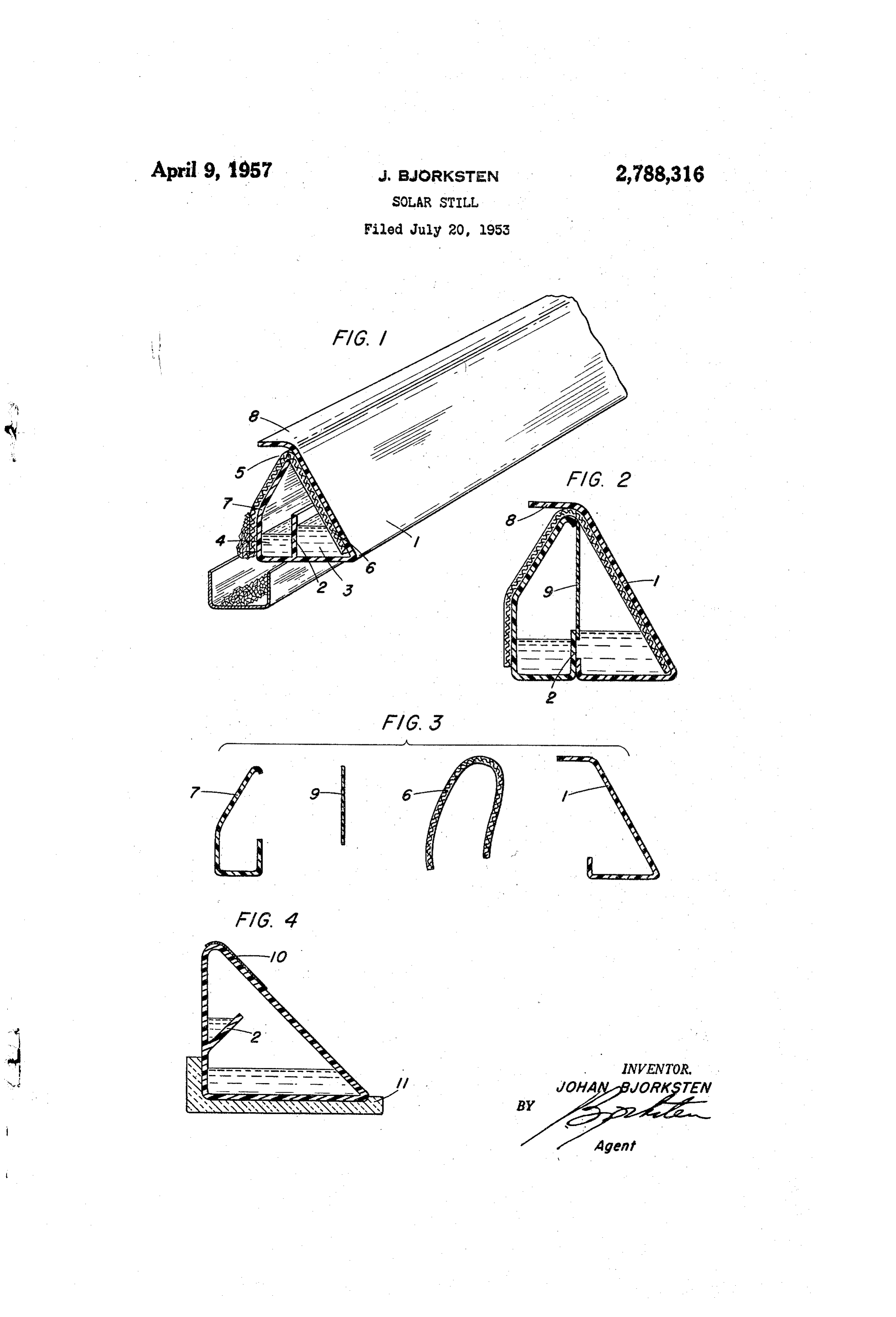
extrusion in longitudinal sections, and these have been cemented together at partition 2. In addition, there is provided a thin moisture vapor, but water impermeable 2,788,316 diaphragm 9 which has for its purpose to prevent saline Water from being splashed over into the distilled water
SOLAR STLL section when the tube is handled or when salt water is Johan Bjorksten, Madison, Wis. pumped into the tube.
Figure 3 shows the component parts of Figure 2 before
Application July 20, 1953, Serial No. 368,992 assembly.
6 Claims. (C. 202-234) Figure 4 shows a still different embodiment. Here the wick has been dispensed with, and instead temperature differential is achieved by means of a reflective coating 10 in the upper portion of the tube. The lower portion is placed in a heat insulating dark cradle 11. The partition
This invention relates to methods for utilizing solar 5 is oblique and set so as to catch any water condensing in energy, and it also relates to methods for preparing po the area from which heat radiation is reflected by means table water from salt water such as sea water. of the reflecting coating 0.
Heretofore many procedures have been suggested for in embodiments and 2 it may also be desirable to this purpose, including various solar power actuated water place Such a reflectant coating on the overhang portion 8 distilling devices. These devices of prior art, however, 20 for still better shielding of the cool wall section. have the disadvantage of inherently costly construction, From the standpoint of manufacture, I prefer to ex high maintenance and insulation costs. trude separately the salt water and the potable water An object of the present invention is a solar power halfs of the device, and then to glue them together ad operated heat differential still, which can be made con hesively, employing and inserting the porous membrane tinuously, from extrudable plastic or other materials, in 25 as they are being assembled. The wick is also positioned unlimited lengths. Due to the longitudinal extension of before the two halfs are adhered together. As adhesive this distillation device, which for most applications will may use a solution of the plastic of which the device be measured in miles, a large total output can be ob is made or a solvent therefor, or I may use any other suit tained in spite of relatively low output per unit area. able adhesive of sufficient bond strength to the plastic Further objects will become apparent as the following 30 used. I may also heat-weld the sections. The wick 6 detailed description proceeds. is made from a material to which salt crystals have rel In further describing the invention, reference is made atively low adhesion such as, for example, polyacrylates, to the drawings, of which Figure 1 is a perspective view polyvinyl chloride, polyvinylidene chloride fabric, glass, showing partial cross-section, partial longitudinal aspect nylon, or polyacrylonitrile fabric. Generally speaking, of one embodiment of the invention; Figure 2 shows a 35 Synthetic fabrics having a high degree of slickness and cross-section of another embodiment of the invention; Sodium chloride repellance are preferred. The wick is Figure 3 shows, in cross-section, the component parts of preferably colored black, or dark, for maximum heat the embodiment of Figure 2 before assembly; and Figure absorption, at least in the section inside the tube. 4 shows, in cross-section, a still further embodiment. The salt accumulated on the wick may be removed pe Referring now to Figure 1, the device of the invention 40 riodically or it may be arranged to drop by gravity into a comprises a tube 1 of inherently unlimited length. This trench which is suitably positioned paralleling the still tube is longitudinally divided by a partition 2 into two tube.
parts, which are connected with each other in the space As construction material, I basically prefer to employ above the partition into two portions 3 and 4. In the transparent plastics, having a dimensional stability ade upper part of the tube there is a slit 5 which is suitable to quate for the purpose intended. For instance heat sta permit the placement of the wick 6 so that one portion 45 bilized acrylics, polyacrylonitriles, polyvinylidene or of this wick is inside the compartment 3 and the other polyvinyl chloride, Sulfur dioxide-butene type, or other side of the wick is outside the tube essentially covering Sulfon resins, polyfluorochloroethylenes, polystyrenes, wall-section 7 of this tube on the opposite side. Above polyethylenes, co-polymers of the above, and the like, the wick the tube is extended to an overhanging portion 50 may be employed. To facilitate entry of the radiation, I 8. The stills thus constituted are desirably at least 100 may use a thin film, adhered over a slot in the extruded feet long, and preferably more than 4 mile long. tube, as the wall on the salt water side. In using the invention, section 3 is filled with saline The water vapor permeable membrane 9 is convenient water and the entire device is so oriented that the sun in order to prevent accidental splashing or intermingling preferentially impinges on the side of the tube which 55 of Salt water and potable water; however it is not an ab holds the saline water and in which the wick is inside Solute necessity for the invention. This membrane may the tube. The saline water in 3 is sucked by capillary be for example a very thin polyethylene membrane, or it forces onto wick 6 through slit 5 and onto the portion Inay be a membrane of regenerated cellulose, or poly of the wick which hangs outside the tube on side 7 vinyl alcohol, or of any plastic, which is intermilled with opposite the salt water side. Thus the saline water will 60 a Solid material of any kind which is not wettable by the evaporate from the device and this induces cooling of plastic or with the solvent therefor used in milling or mix wall 7. This results in a cooling in this wall so that a ing. In this fashion small cracks in the membrane will temperature differential exists between wall 7 on one exist through which water vapor can readily pass. hand, and salt water compartment 3 and the opposite The cross-sectional form of the device is not critical, 65 though it is preferred that the lower portion be broader wall of the tube on the other hand.
As a result, water will evaporate from section 3 and than the upper portion, for convenience in positioning. from the wick over section 3 and will condense on the The wall of the saline section 3 may be made of thin shaded and evaporation cooled wall 7. This water will sheet or film stock adhesively bonded to the structure. accumulate into section 4 of the tube, and can be drained The cross-sectional partition 2 should leave some vapor off through a drainage opening or openings (not shown). 0. passage between the said sections and should be shorter A somewhat different embodiment is shown in cross in cross-section than the diameter of the pipe. section in Figure 2. Here the tube has been made by The reflective coating 10 may be either outside or
Page 3
- 2,788,816 : -.
inside of the tube, and may be applied as a reflective foil, liquid, parallel to said first channel, condensing means a sprayed, spluttered vacuum deposited mirror film, consisting of a first non-porous wall extending upwardly aluminum paint, titanium oxide paint, or in any other from the outer side of said second channel, a transparent manner known to the art, achieving high reflectivity for Second non-porous wall extending upwardly from the solar radiation. outer side of said first channel, the upper portion thereof It is thus obvious that the scope of the invention is being spaced apart from the top edge of said first wall broad and is not to be limited excepting by the claims, in to provide a slit thereinbetween, and means for cooling which it is my intention to cover all novelty inherent in said condensing means consisting of a sheet of opaque this invention as broadly as possible in view of prior art. dark colored liquid absorbent material overlying and Having thus disclosed my invention, claim: 0. in contact with said first wall. 1. A device for distilling salt water by solar energy, 5. Seiar distiliation apparatus consisting essentially of said device comprising in combination a tube divided into a first channel adapted to contain liquid which contains two longitudinally extended parallel channels defined by impurities, a second channel adapted to contain distilled transparent walls having a vapor-admitting passage be liquid, parallel to said first channel, condensing means tween them, and having further a dark colored opaque consisting of a first non-porous wall extending upwardly wick which covers substantially the entire upper portion from the outer side of said second channel, a transparent of said device, being positioned inside said device on one SecCnd non-porous wall extending upwardly from the side, extending through a slot at the apex of the device outer side of said first channel, the upper portion thereof and positioned outside said device on the other side, said being spaced apart from the top edge of said first wall wick being made of a smooth synthetic material. 20 to provide a slit thereinbetween, and means for cooling 2. A tubular solar still characterized by a longitudinal said condensing means consisting of a sheet of opaque partition throughout the length thereof, said partition dark colored liquid absorbent material overlying and in dividing said tubular still longitudinally into two chan contact with said first wall, said sheet extending through nels; said partition being lower than the height of said the slit between said first and second walls and occupy still; further characterized by a longitudinal slit in the 25 ing Substantially the entire area of said slit, thence ex upper portion thereof and a dark colored opaque wick tending downwardly, underlying and in contact with said passing through said slit, said wick extending substantial second wall, into said first channel. ly along both sides of said still, inside the still on one 6. Solar distillation apparatus consisting essentially of side and outside the still on the other side, said sides being a first channel adapted to contain liquid which contains transparent. 30 impurities, a second channel adapted to contain distilled 3. Solar distillation apparatus consisting essentially of liquid, parallel and adjacent to said first channel, sep a first channel adapted to contain liquid which contains arated therefronn by a common partition and having a impurities, a second channel adapted to contain distilled bottom substantially coplanar therewith, condensing liquid, parallel and adjacent to said first channel and means consisting of a first non-porous wall extending up separated therefrom by a common side, condensing means Wardly from the side of said second channel furthest consisting of a first non-porous wall extending upwardly from said first channel, a second transparent non-porous from the side of said second channel furthest from said wall extending upwardly from the side of said first chan first channel and inwardly over said channel, a trans nel furthest from said second channel, spaced apart from parent second non-porous wall extending upwardly from the top edge of said first wall to provide a slit therein the side of said first channel furthest from said second 40 between, and means for cooling said condensing means channel and inwardly over said first channel spaced above consisting of a sheet of opaque dark colored liquid ab and apart from said first wall and extending thereover, sorbent material overlying and in contact with said first means for cooling said condensing means consisting of a wall.
sheet of opaque dark colored liquid-absorbent material overlying and in contact with said first wall, said sheet 45 References Cited in the file of this patent extending through the space between said first and second UNITED STATES PATENTS walls and substantially closing said space to the passage of air therethrough other than through passages within 2,398,292 Delano ---------------- Apr. 9, 1946 said sheet, thence extending downwardly, underlying and 2,402,737 Delano ---------------- June 25, 1946 in contact with said second wall, into said first channel. 5 0 2,413,101 Delano --------------- Dec. 24, 1946 4. Solar distillation apparatus consisting essentially of 2,427,262 Delano ---------------- Sept. 9, 1947 a first channel adapted to contain liquid which contains 2,445,350 Ginnings -------------- July 20, 1948 impurities, a second channel adapted to contain distilled 2,455,835 Ushakoff---------------- Dec. 7, 1948
Provenance
- Collection
- Cited prior art
- Original PDF
- patentimages.storage.googleapis.com →
- Filed
- 1953-07-20
- Pages
- 3
- Method
- pdftotext (the PDF's own text layer) + pdftoppm 300dpi page scans
- Source
- Google Patents bibliographic record
- Granted
- 1957-04-09
- Inventors
- Bjorksten Johan
- Transcribed from
- patentimages.storage.googleapis.com →