patent · US4058110
Wide angle solar heat collection system
15 November 1977
Page 1 — bibliographic record
United Sta (11) 4,058,110 Holt - (45) Nov. 15, 1977 54 WIDE ANGLE SOLAR HEAT COLLECTION 1,673,429 6/1928 Vinson ................................. 126/271 SYSTEM 2,259,902 10/1941 McCain ................................ 126/271 2,467,885 4/1949 Freund ........ 126/271 76) Inventor: F. Sheppard Holt, 46 Emerson Road, 3,227,153 1/1966 Godel et al. ......................... 126/271 Winchester, Mass. 01890 3,321,012 5/1967 Hervey ................................. 126/271 3,866,285 2/1975 Clark .................................... 126/27
22 Filed: Aug. 5, 1975 Primary Examiner-Kenneth W. Sprague Attorney, Agent, or Firm-Joseph E. Rusz; Sherman H.
51) Int. Cl. ................................................. F24J 3/02 Goldman 52 U.S. C. ............................. 126/271; 350/175 SL; 57 ABSTRACT
(58) Field of Search ............... 126/270, 271; 237/1 A; A cylindrical reflector or lens is used under aberrated 350/175 R, 175 SL conditions in conjunction with an enlarged primary (56) References Cited collector to obtain wide angle scanning performance that will allow concentration of solar radiation without
1,093,498 4/1914. Thring ................................. 126/27 1,345,758 7/1920. Folsom ................................. 126/27 2 Claims, 11 Drawing Figures
SYMMETRY
Page 2
Drawing sheet — no readable text.
Page 3
Drawing sheet — no readable text.
Page 4
Drawing sheet — no readable text.
Page 5
Drawing sheet — no readable text.
Page 6
lant temperatures are available, thereby allowing for use
WIDE ANGLE SOLAR HEAT COLLECTION of the system for refrigeration purposes. SYSTEM It is another object of this invention to provide a solar STATEMENT OF GOVERNMENT INTEREST 5 energy collection system which utilizes right circular cylinder reflectors or circular cylinder lenses to par
The invention described herein may be manufactured tially focus solar energy, thereby allowing for the pro and used by or for the Government for governmental duction of higher temperatures than has been achieved purposes without the payment of any royalty thereon. using existing, wide angle, non-tracking devices. BACKGROUND OF THE INVENTION It is still another object of this invention to provide a 10 solar energy collection system that utilizes a parabolic
This invention relates generally to solar heat collec cylinder reflector operating in a defocused condition to tion devices and more particularly to one which utilizes produce higher temperatures than have been achieved a cylindrical reflector or lens under aberrated condi using existing, wide angle, nontracking devices. tions to eliminate and/or reduce the tracking of the sun A further object of this invention is to provide a solar over a period of days, while at the same time achieving 15 heat collection system which is easy and economical to a concentration of solar radiation suitable for use with a produce of conventional, currently available materials solar heating or energy storing system. that lend themselves to standard mass production manu Previously, solar radiation collectors were either flat facturing techniques.
area reception devices for moderate heat temperatures 20 These and other advantages, features and objects of or focusing devices such as paraboloids, parabolic cylin the invention will become more apparent from the foll ders or lenses to concentrate the solar radiation at rela lowing description taken in conjunction with the illus tively high temperatures. The flat area devices are capa trative embodiments in the accompanying drawings. ble of collecting sufficient heat only for moderate heat ing temperatures while the narrow angle receptivity in 25 BRIEF EDESCRIPTION OF THE DRAWINGS at least one plane of scan of the focusing type devices FIGS. 1 and 2 are pictorial representations of a cylin requires continuous scanning in order to track the sun's drical reflector and lens, respectively, in conjunction path to obtain high temperatures. Complicated tracking with primary collectors. These Figures serve to specify systems have raised the costs of this type of device to the plane of symmetry for the reflector system and the the extent that it has not become practical. 30 lens system;
SUMMARY OF THE INVENTION FIG. 3 is a diagrammatic representation, partly in cross section, of a circular cylinder reflector in conjunc
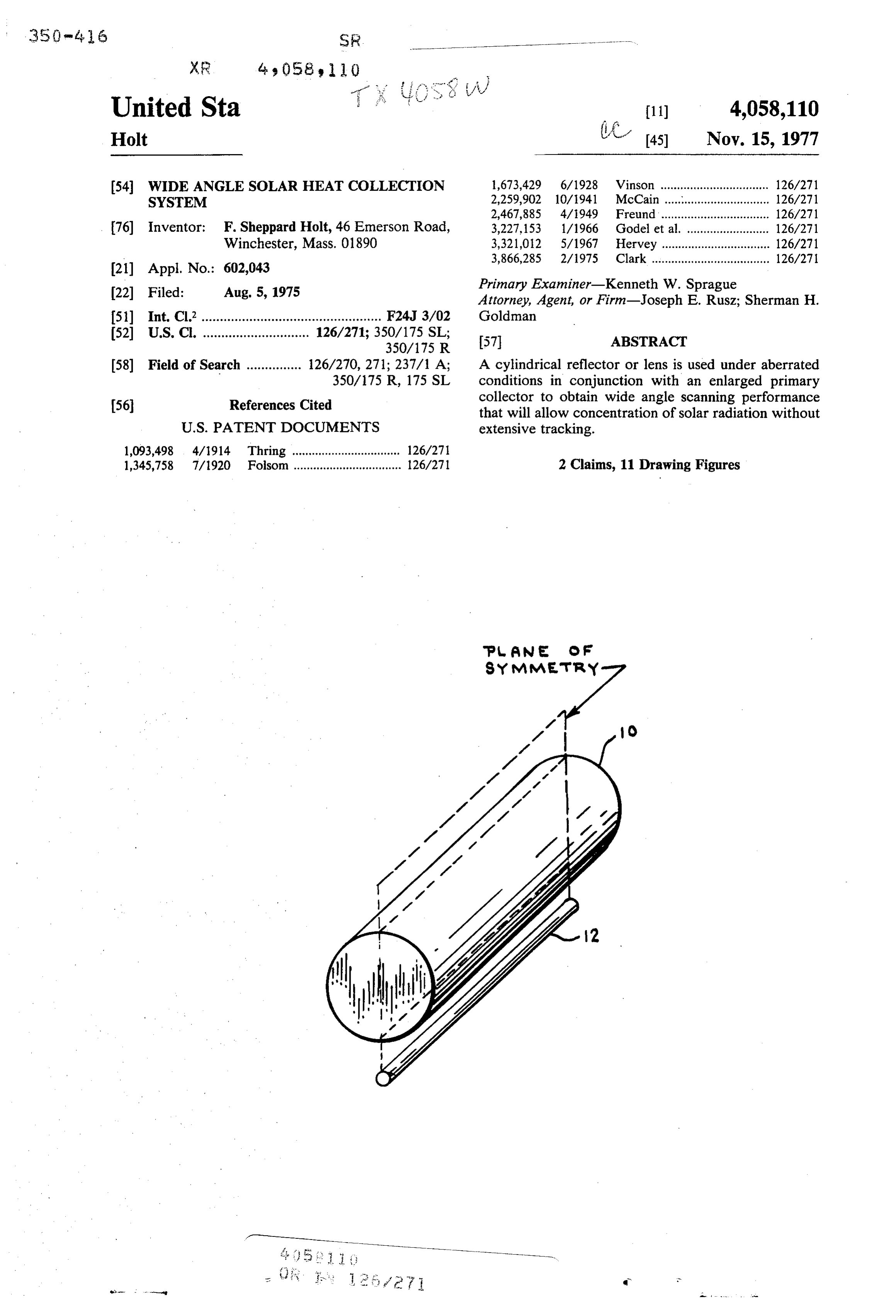
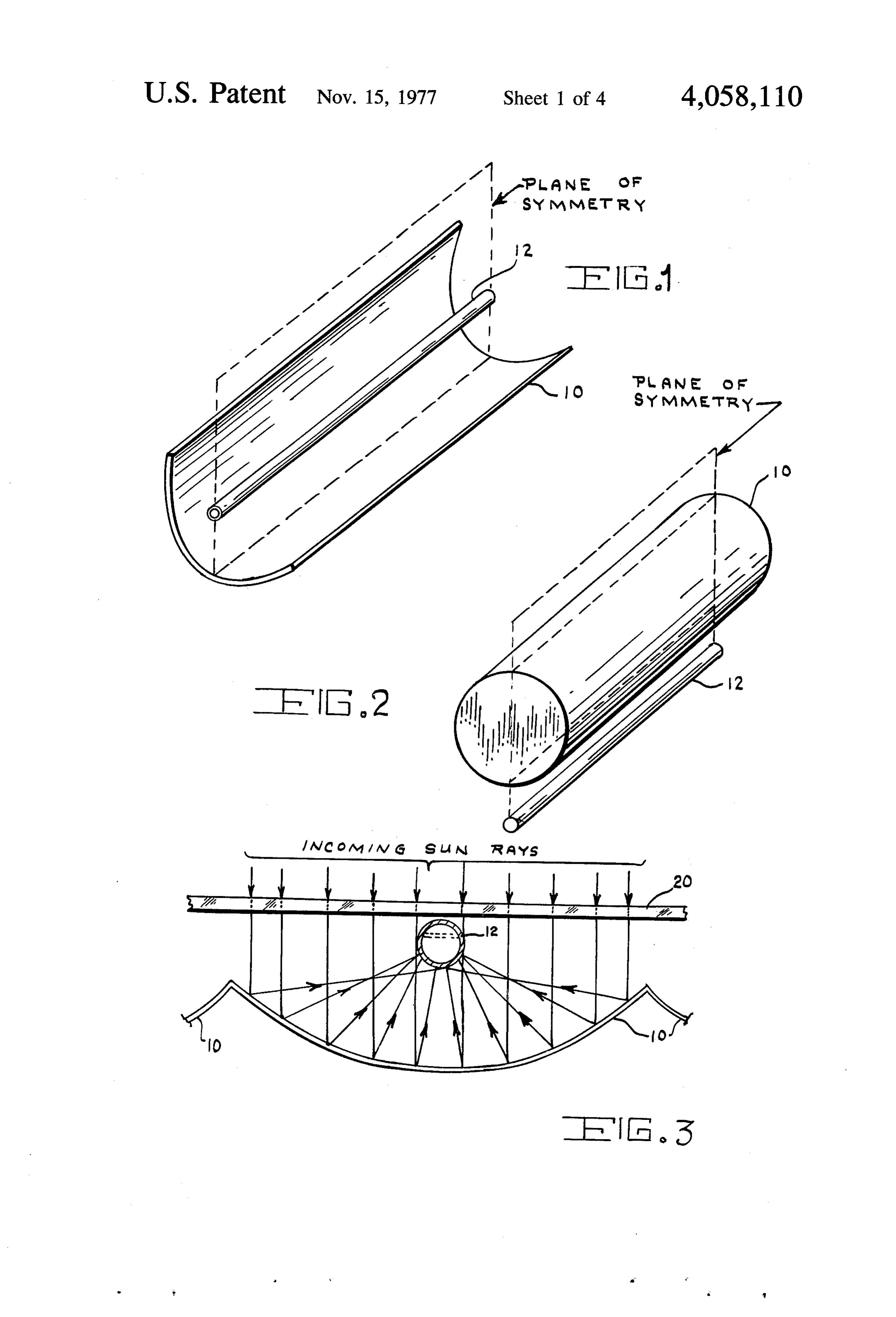
This invention provides for the utilization of cylindri tion with an enlarged primary collector. The incoming cal reflectors or lenses operating under aberrated condi rays are parallel to the plane of symmetry and the re tions in conjunction with an enlarged primary collector 35 flected rays illustrate the aberration characteristic of to produce scanning properties that allow for the track circular systems wherein the primary collector inter ing of the sun for extended periods of time with no cepts all rays;
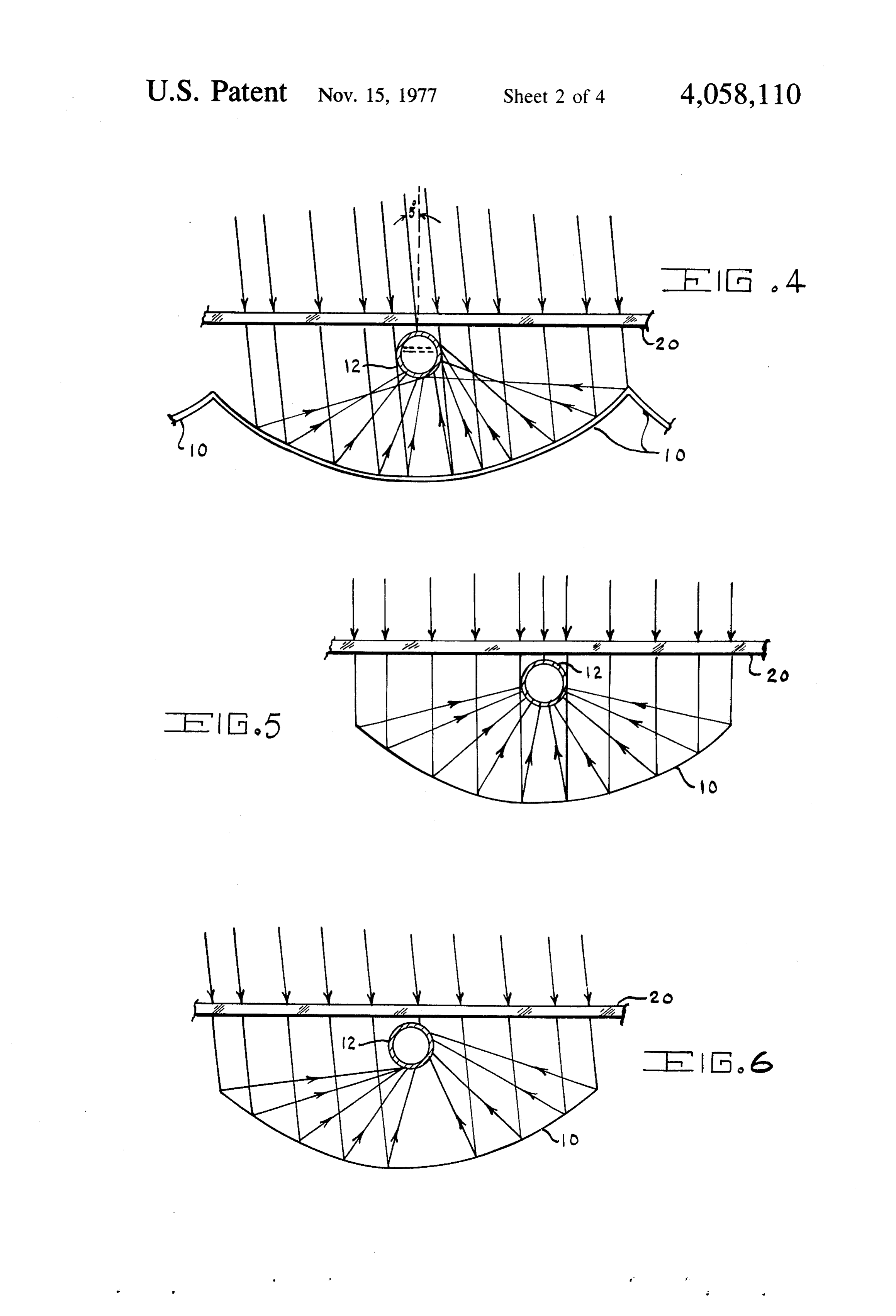
mechanical motion. FIG. 4 is a diagrammatic representation of the same Accordingly, it is a primary object of this invention system as shown in FIG. 3 but with the incoming rays to provide a solar heat collection system which utilizes 40 tilted 5 relative to the plane of symmetry with, as in cylinder reflectors or lenses operating under aberrated FIG. 3, the primary collector intercepting all rays; conditions. FIG. 5 shows a cross section of a parabolic cylinder It is another object of this invention to provide a solar reflector in conjunction with an enlarged feed where heat collection system which allows for the tracking of the incoming rays are parallel to the plane of symmetry the sun for extended periods without requiring mechan 45 and the reflected rays indicate a defocused condition at ical motion. all points where they intersect the surface of the pri It is still another object of this invention to provide a mary collector;
solar heat collection system which provides a concen FIG. 6 illustrates the same system as FIG. 5 but with tration of solar radiation for high temperature heating. the incoming rays tilted 5 relative to the plane of sym It is a further object of this invention to provide a 50 metry with the primary collector intercepting all rays solar heat collection system which eliminates complex thereby illustrating by the symmetry of the system that tracking systems. the same condition will hold if the incoming rays make It is a still further object of this invention to provide an angle of + 5° with the plane of symmetry; a solar heat collection system which is easily adapted to FIG. 7 is a diagrammatic representation of heat col conventional solar heating equipment. 55 lection units of the circular cylinder lens type with ray Another object of this invention is the provision of a tracing that illustrates the inherent aberration of such a solar heat collection system which is lower in cost than circular system;
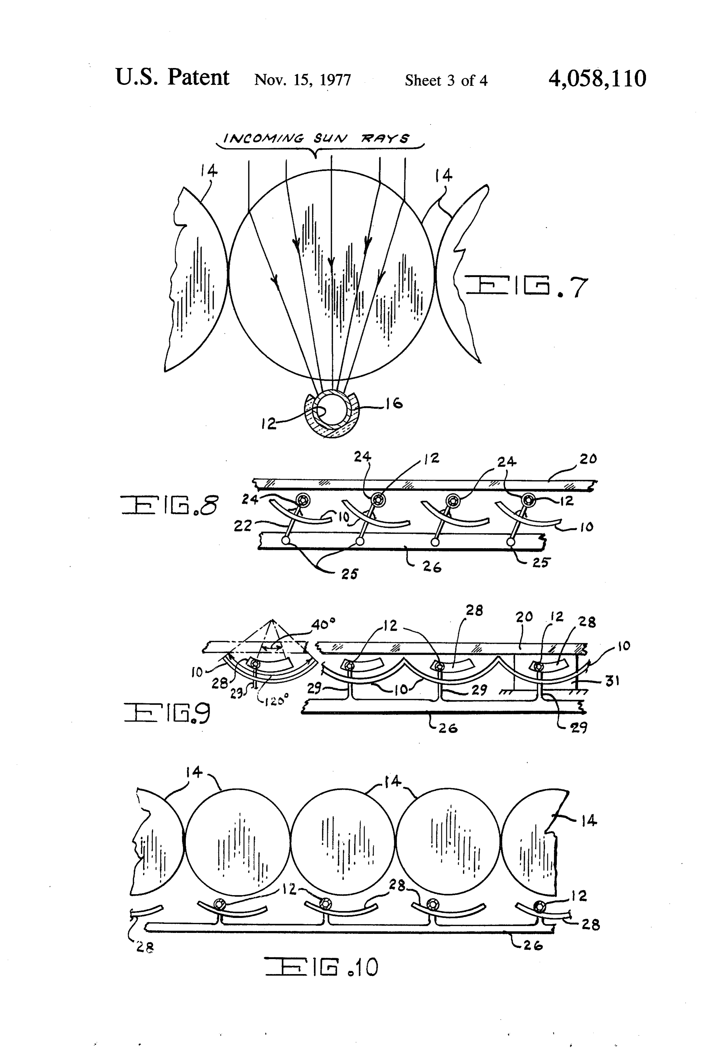
those currently available with similar heat collecting FIG. 8 is a schematic representation of a scanning capabilities. system for either the circular or the parabolic type cy Still another object of this invention involves the lindrical reflector wherein the motion of the reflector is provision of a solar heat collection system with simpli a rotation about the primary collector; fied scanning arrangements. FIG. 9 shows a scanning system applicable to the A further object of this invention is to provide a solar circular cylindrical reflector wherein the reflector stays energy collection system from which higher circulant fixed and the feed is moved on a circular arc concentric temperatures are available, thereby leading to a more 65 with the reflector;
efficient solar heating system. FIG. 10 is a diagrammatical representation of an A still further object of this invention is to provide a array of lens collectors that utilize the motion of the solar energy collection system from which higher circu primary heat collector to achieve scan; and
Page 7
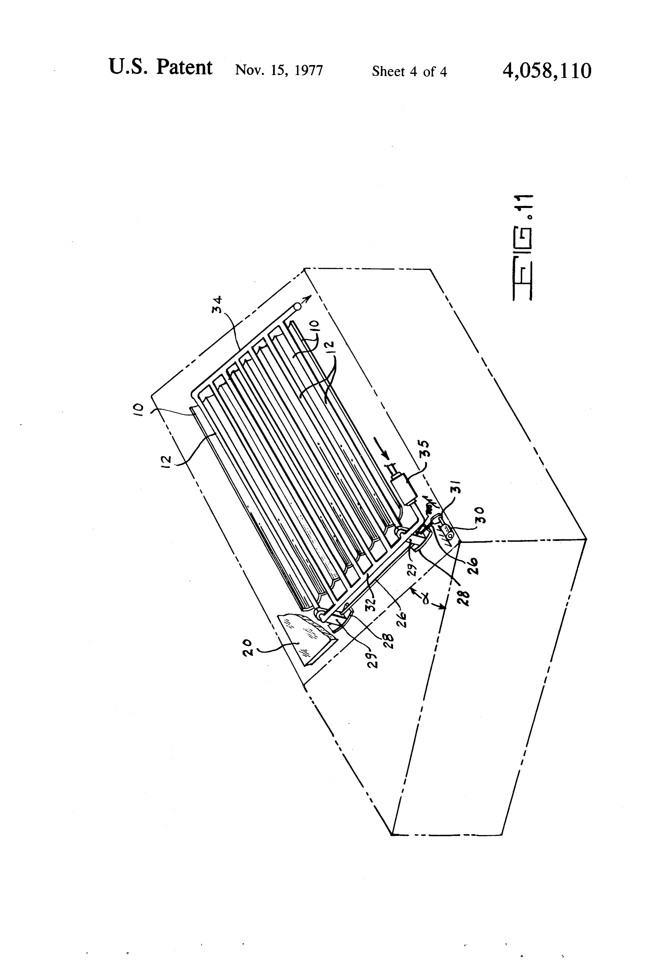
FIG. 11 is a schematic illustration of a roof installa collected by the reflector is focused. The collector 12, tion of a solar heat collection system. as described relative to FIGS. 3 and 4, would have a DESCRIPTION OF THE PREFERRED circulant liquid therein for providing a heat transfer EMBODIMENT medium. Also, as in the previously described conven tional installation, a transparent weather protection
A circular cylinder reflector or lens can be used with sheet 20 is placed above the system. The ray tracings of a properly designed primary collector to achieve heat FIG. 5 illustrate the heat collection system in a plane concentrations of up to 7.5 times those obtained with normal to the plane of symmetry while FIG. 6 has a 5 flat plate systems. FIG. 1 shows a cylindrical reflector tilt in the incoming rays relative to the plane of symme 10 with a primary heat collector 12 located in the focal O try. In both instances the location of the primary collec region and FIG. 2 shows a circular cylindrical lens 14 tor 12 is chosen to collect all of the energy incident mounted above a primary heat collector 12 located in upon the collectors. The circular cylinder of FIGS. 3 the lens focal region. The plane of symmetry is clearly and 4 have fabrication and economical advantages over depicted in both Figures the parabolic cylinder since the inherent symmetry of It is an inherent, well-known property of cylindrical 15 the circular reflector makes it easier and less expensive systems that their focusing properties remain essentially to construct and also to test for tolerance maintenance. unchanged as the direction of the incident energy is In contrast to circular systems the parabolic cylinder scanned over a very wide range of angles in the plane of reflector is well focused for incident rays parallel to the symmetry. The incident energy in the plane of symme plane of symmetry but suffers increasing aberrations as try can vary 60 in the plane before there is a drop of 20 the incident rays are scanned in planes normal to the 50% in energy applied to the primary collector; how plane of symmetry. FIGS. 5 and 6 show that the para ever, normally in a well focused system, the scan is only bolic shape performs as well as the circular shape out to a couple of degrees. With the instant invention a the design scan angle --5. However, beyond. --5 scan - 10-12 scan perpendicular to the plane of symmetry the aperture efficiency of the parabolic system de produces the 50% loss. 25 creases more rapidly than with the circular geometry The schematic representation of FIG. 3, showing the and is down about 9 db at a scan angle of H 10.5. cross section of a solar heat collection system in a plane FIG. 7 illustrates a series of circular cylindrical lenses normal to the plane of symmetry, utilizes a reflector or 14 each of which would have a primary collector 12 a series of reflectors 10 above each of which is mounted with insulation 16 around that portion of the feed upon a primary heat collector 12. A circulant liquid is made 30 which the incoming rays do not impinge. Proper design to circulate within the primary heat collector 12 to of the primary collector is carried out using a ray trac provide for heat transfer to a storage arrangement, for ing technique entirely similar to that described above example. In conventional installations a transparent for the design of the system shown in FIG. 3. Again, as weather protection sheet 20 would be provided over described relative to FIG. 3, a circulant liquid is pro the reflectors and collectors. Proper design of the pri 35 vided within the collector 12.
mary collector 12 consists of (a) ray tracing the desired It is primarily the property of having reflectors or portion of the reflector or lens in a plane normal to the lenses with moderate scanning capability in planes nor plane of symmetry, (b) scanning the direction of the mal to the plane of symmetry that enables the instant incoming energy in this normal plane by the desired device to produce superior tracking performance with a amount, and (c) then choosing a collector configuration 40 structure that differs from other focusing devices which as small as possible that intercepts as many rays as possi have been used for solar energy collection, for example, ble. parabolic cylinders operating in a perfectly focused FIG. 4 illustrates the results obtained with a 5 tilt of condition. Circular systems inherently possess aberra the incoming energy relative to the plane of symmetry. tions but circular symmetry insures that the degree of The ray tracings of FIGS. 3 and 4, if superimposed, 45 aberration does not change with scan angle in planes contain sufficient information to determine the proper normal to the plane of symmetry. It is this wide angle location and size for the circular primary collector 12. property that allows properly designed primary collec The design shown in these Figures is for the case where tors to produce systems with moderate scanning prop the desired sector of the circular reflector is about 80 erties normal to the plane of symmetry. Such systems and the desired scan in a plane normal to the plane of 50 can still achieve sufficient wide angle reception for symmetry is +5. The ray traces of FIGS. 3 and 4 show useful application and simultaneously concentrate the that the primary collector need not be circular in cross incoming solar radiation by a factor as high as 7.5. This section but could be considerably flattened on top to type of arrangement, when given an east-west orienta reduce collector cross section (see dotted lines in collec tion of the collectors, enables the sun to be tracked tors 12). It is a property of the circular geometry that 55 throughout the major portion of its useful arc by means the aperture efficiency of the system decreases slowly of mechanical scanning in small steps occurring at inter beyond the design scan angles. For the design shown in vals in the order of many days. For example, with a FIGS. 3 and 4 scanning out to +10.5 in planes normal concentration ratio of 7.5 tracking could be achieved to the plane of symmetry decreases the aperture effi with step scans of from 0.5° to 4 at ten day intervals. It ciency by only about 2 db. Depending on the efficiency 60 is characteristic of these systems that the higher the loss that can be tolerated, this system can be used well concentration ratio the smaller and more frequent the beyond the illustrated scan value of +5. needed step scans.
FIGS. 5 and 6 are utilized to illustrate the scan prop This invention contemplates both manual and auto erties with respect to a parabolic cylinder reflector. In matic scanning and could be achieved by moving the these Figures the reflector 10 is a parabolic cylinder 65 primary collector relative to the reflector or lens or vice which is deliberately made to have an aberrated condi Versa. Moving the primary collector makes it easier to tion such that the normal line of focus of a conventional maintain a fixed outer surface to the configuration; parabolic cylinder now has an area in which the energy however, there is some reduction in aperture efficiency.
Page 8
Examples of two different scanning systems for reflec efficiency. Insulation 16 may be provided, as is conven tor type collectors are shown in FIGS. 8 and 9. As can tional in the art, to insulate the primary heat collectors be seen in these Figures the transparent weather sheet everywhere except where they intercept the focused 20 covers the primary heat collectors 12 and its asso solar energy. Thermal insulation, of course, is provided ciated cylindrical reflectors 10. for other pipes in the system which conduct the circu In FIG. 8 each of the reflectors is secured to a link 22 lant. Careful control of the solar and surface finish of which is journaled about its primary heat collectors 12 the active absorption portion of the primary heat collec at 24. This arrangement would be at the ends of the tor can be expected to optimize heat transfer. reflectors. The ends of the links 22, remote from the A typical installation of an array of the reflector type primary heat collectors 12, are connected with and 10 collectors 10 is illustrated in FIG. 11 wherein the sys pivoted at 25 to a scan control link 26. A horizontally tem is mounted at approximately the local latitude angle applied force causes movement of the scan control link a, which is best achieved by setting the pitch of the roof 26 to effect a rotation of the right circular cylinder at this angle. The cover 20, illustrated in prior Figures, reflectors 10. An alternative arrangement (not shown) has been cut away in the interest of clarity. The orienta would be to provide a pinion gear on the outer periph 15 tion of a house in the northern hemisphere utilizing this ery of the journal for a rack or motor driven gear in system is best arranged with its longitudinal axis on an mesh therewith. The embodiment of FIG. 8 could be east-west line with the system being provided on the used for either the right, circular cylinder reflectors or southern exposure. One function of the transparent the defocused parabolic reflectors. weather protection sheet 20 is to act as a thermal insula FIG. 9 represents an embodiment wherein the pri 20 tion layer such that the space thereunder forms a heat mary collectors 12 are moved with respect to the right trap. In FIG. 11 the circular cylinder reflectors may be circular cylinder reflectors 10 along an arc of approxi moved for tracking as illustrated in FIG. 8 or the pri mately 40' about the same center of curvature as that of mary heat collectors 12 may be moved as shown in the reflectors. The ends of the primary collectors 12 FIG. 9 with right circular cylinder reflectors. The sche collocated at the ends of the reflectors 10 could be 25 matic representation shown in the Figure comprises a placed in a slotted cam or guide arrangement 28 which drive system wherein the primary heat collectors 12 would limit their positions to points along the 40' arc. A have rigid extensions 29 which ride on cam guides 28 scan control linkage bar 26 in this case would be se such that motion of the scan control link 26 causes cured to the primary collectors 12 by a rigid link 29 movement of the collectors 12 along an arc concentric such that a generally horizontal application of force 30 with that formed by the reflectors 10. Movement of the would cause the collectors 12 to travel along the guide link or bar 26 may be effected manually or by a motor slots 28. Each slot 28 could be provided in an end plate 30 having a cam 31 on the end of the shaft to apply a 31 as depicted schematically at the right end of FIG. 6. force in the horizontal direction to element 26. Of It should be understood that the means for operating course, any means for causing movement of bar 26 the embodiments of FIGS. 8 and 9 do not have to be 35 would be acceptable. The collection system would have applied to each reflector or collector. Only the end a coolant pump 35 attached to the manifold 32 for elements need be controlled when the elements are pumping the circulant through the system. The collec ganged. Also, any means for producing the appropriate tor system of this invention could be applied to any motions may be utilized. When lenses are used, the solar heating system, for example, that described in the primary heat collector 12 is moved on an arc concentric patent application of Carlyle J. Sletten, titled "Solar with the lens as is best illustrated in FIG. 10. In this Energy Apparatus and Method' filed on even date instance the scan control bar 26 rigidly connected the herewith.
primary collectors 12 which are provided with guides Although the invention has been described with ref. 28 in order to control their position along the arc and erence to particular embodiments, it will be understood operates in the manner similar to that described relative 45 to those skilled in the art that the invention is capable of to FIG. 9. a variety of alternative embodiments within the spirit For practical operation of a system a tolerance of and scope of the appended claims.
0.03125 inch in circular cross section contour of the I claim:
reflectors is probably sufficient for cross section aper 1. A solar energy collection system comprising right tures on the order of one foot. Locally, however, the 50 circular cylinder lens means for aberrated focusing of surface should be optically smooth and highly reflec solar energy such that said lens means exhibits moderate tive. Lenses should have surfaces which are locally scan properties in a plane normal to the plane of symme optically smooth and the lens material should be highly try; and a hollow body located in the focal region of transparent. said lens means, said body having an inlet and an outlet It is submitted that systems of the type described are 55 to render it capable of having a circulant flow there able to achieve a concentration of solar radiation to through, said body being of a size to accommodate produce temperatures in a static black body collector in focused solar energy received over a moderate scan the order of 500' C. The heat available for transfer to a angle in a plane normal to the plane of symmetry of said circulant liquid such as water or ethylene glycol de eaS.
pends upon the materials utilized in the construction as 2. A system as defined in claim 1 including means for well as the shape and surface finish of the primary col causing relative movement between said body and said lectors. The rate of flow of the circulant, the surface lens means in order to maintain energy received by said finish of the reflector or lens and the amount of reradia lens means to be focused on. said body. tion of the primary collector also affect the heat transfer k . . .
Provenance
- Collection
- Cited prior art
- Original PDF
- patentimages.storage.googleapis.com →
- Filed
- 1975-08-05
- Pages
- 8
- Method
- pdftotext (the PDF's own text layer) + pdftoppm 300dpi page scans
- Source
- Google Patents bibliographic record
- Granted
- 1977-11-15
- Inventors
- F. Sheppard Holt
- Transcribed from
- patentimages.storage.googleapis.com →