patent · US3886998
Combination solar water heater and chiller
3 June 1975
Page 1 — bibliographic record
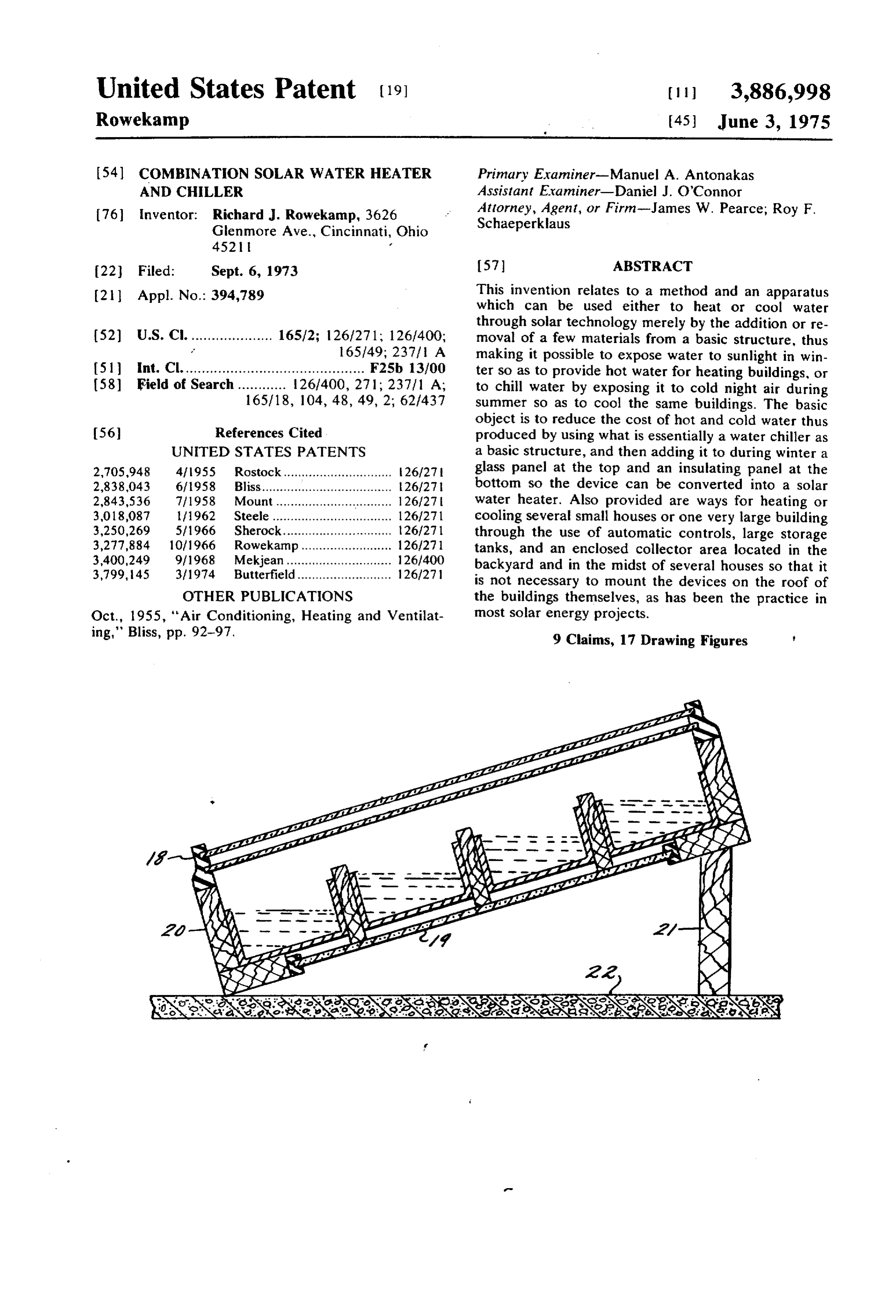
United States Patent (19 11 3,886,998 Rowekamp (45) June 3, 1975
(54) coMBINATION SOLAR WATER HEATER Primary Examiner-Manuel A. Antonakas AND CHILLER Assistant Examiner-Daniel J. O'Connor 76) Inventor: Richard J. Rowekamp, 3626 Attorney, Agent, or Firm-James W. Pearce; Roy F. Glenmore Ave., Cincinnati, Ohio Schaeperklaus
22 Filed: Sept. 6, 1973 (57) ABSTRACT 21 Appl. No.: 394,789 This invention relates to a method and an apparatus which can be used either to heat or cool water through solar technology merely by the addition or re 52 U.S. C. .................... 16572; 126/271; 126/400; moval of a few materials from a basic structure, thus 165149; 237 fi A making it possible to expose water to sunlight in win (51 int. Cl............................................. F25b. 13100 ter so as to provide hot water for heating buildings, or 58 Field of Search ............ 126/400, 271; 237/1 A; to chill water by exposing it to cold night air during 165/18, 104, 48, 49, 2; 62/437 Summer so as to cool the same buildings. The basic object is to reduce the cost of hot and cold water thus 56 References Cited produced by using what is essentially a water chiller as UNITED STATES PATENTS a basic structure, and then adding it to during winter a 2,705,948 4fl955 Rostock.............................. 26/27 glass panel at the top and an insulating panel at the 2,838,043 6fl958 Bliss.................................... 26/27 bottom so the device can be converted into a solar 2,843,536 7/1958 Mount ....................... . . . . . . . . . 126/27 water heater. Also provided are ways for heating or 3,018,087 lf1962 Steele................................. 1261271 cooling several small houses or one very large building
through the use of automatic controls, large storage tanks, and an enclosed collector area located in the 3,400,249 9/1968 Mekjean............................. 126/400 backyard and in the midst of several houses so that it 3,799,145 3/1974 Butterfield.......................... 126/27 is not necessary to mount the devices on the roof of OTHER PUBLICATIONS the buildings themselves, as has been the practice in Oct., 1955, "Air Conditioning, Heating and Ventilat most solar energy projects. ing," Bliss, pp. 92-97. 9 Claims, 17 Drawing Figures
Page 2
Drawing sheet — no readable text.
Page 3
Drawing sheet — no readable text.
Page 4
Drawing sheet — no readable text.
Page 5
COMBINATION SOLAR WATER HEATER AND vision each device as being 8 foot long, 2 feet wide, and CHILLER only 3% inches high, as a chiller; – 5 inches high as a if sunlight is to become appealing as a commercial Solar water heater, and each would be filled with about source of energy, the cost of the devices which collect 15 gallons of water. At the present time, wood is far it must be reduced to a hare minimum. The prime ob cheaper than metals or plastics, and affords the struc jective of this invention is to provide such an economi tural strength to support l 25 pounds of water; there cal apparatus, which in effect would be a combination fore, wood is shown on the drawings; and it is the actual solar water heater and chiller, capable of heating and intent to use a 2 inches X 4 inches wood frame, which cooling buildings. To accomplish this, I have designed is really only la inches X 3% inches in its cut size. a chiller as a basic structure, which is constructed of () However, it is to be pointed out that metal or plastics the same shallow trays as is described in my U.S. Pat. could be used if they prove to be economical or practi Nos. 3349573 and 3293872 for desalting ocean water cal. It is intended that a very thin gage aluminum sheet by freezing, except that the shallow trays are arranged will be used to make the narrow shallow pans; this will in banks of four and separated from each other by : reduce material and manufacturing costs; but to keep wood divider, and except that all are contained within 5 the pans from being broken or distorted by the weight a wood frame which acts as the structural support for of the water, a wood divider will be run longitudinally the entire assembly. To this chiller, or basic structure, between all four pans to support them, because when is added a glass panel and an insulating panel, which the water heater is tilted toward the Sun a considerable converts the chiller into a solar water heater. weight is pressing downward due to the slant. To brace An object of this invention is to design a chiller which the aluminum trays from the bottom, four wood sup can also be used as a solar water heater. This requires ports are used as shown on the drawings, and each will a reduction in the width of the solar trays which I have be routed out so the wood dividers will slip into them used for desalting ocean water by freezing through ex and be held firmly in place. In selecting the materials posure to the frigid air of the atmosphere in winter: and design for the materials which convert the chiller preferably the desalting trays would be one to two feet into a solar water heater, the entire theme of economy wide so they can carry as much ocean water as possible. is carried out. the frame for the glass panel is made of But such wide trays are not suitable for a solar water rubber which is extruded in one piece and containing heater, since they must be tilted at a rather sharp angle the rabbet which will hold the glass panes; and the insu toward the Sun during winter when it is far off in the lation is cut so that it can be merely slipped into the southern skies; under such conditions, all the water in bottom portion of the wood frame. a wide tray would pool up at the lower end, while better Still another object of this invention is to use an alu than three-fourths of the tray would expose only bare minum sheet which is alloyed with silicon and manga metal to sunlight. This would result in little heated nese as described in my U.S. Pat. No. 3314414 for a water for the amount of metal involved; - it would be Traughs in A Pool Solar Collector; the aluminum pan wasteful, uneconomical, and impractical. Therefore, a turns black when water containing salt or fluoride is narrow and shallow tray must be employed - about 5 used in the pans and exposed to sunlight. It is to be inches in width; and a bank of four such trays, as shown pointed out that the apparatus of this invention has a on the drawings, has proven very practical in tests and design somewhat similar to my Traughs in A Pool Solar experiments which I have conducted. Collector; but, in principle, both are vastly different. Another object of this invention is to disclose a novel The Traughs in A Pool Solar Collector has an air gap method whereby, through the employment of numer dividing three pans containing water, and accomplishes ous such devices within a fenced area in the backyard quick high temperatures through a combination of ra of several homes or a commercial building, a mainte diation, conduction, and convection. The device of this nance specialist could be hired to repair and operate all invention has only wood dividers running between four the solar equipment; and hot and cold water could be 45 pans so as to strengthen the thin gage aluminum which sold to customers by a solar public utility company. forms the pans; it achieves only moderate tempera Most solar devices invented to date are so designed that tures, but in larger quantities; and accomplishes heat they become a part of the structure which they usually ing chiefly through radiation.
will heat only; - few provide cooling. This means that 5) Another object of this invention is to provide a glass the owner of the building must maintain and operate panel which has a frame that can be easily formed, the devices. Since most homeowners are not techni glazed, and fastened to the basic structure. The rubber cally oriented, nor do they have the time to properly gasket shown in the drawings meets all these require maintain such devices, most solar projects are annoying ments: it can be extruded in one piece at extremely and objectionable to the owner. In this new approach cheap costs; it has cleverly designed rabbets which per for both heating and cooling homes, all the energy mits quick glazing; and rubber cement can be used to would be produced within an enclosed area where the glue it to the wood frame of the chiller. To further devices would be safeguarded from damage, and where speed up glazing, a liquid glazing compound is merely a maintenance man could see that all the equipment is poured into the rabbets, acting as a lubricant as well as working properly, thus assuring the homeowners of 60 a sealer, and the glass panes slip in place very easily. continuous year-round comfort, without the worry and Still another object of this invention is to eliminate trouble with complicated equipment which they them the cost of expensive welding and cutting so as to install selves are unsuited to operate and maintain. piping that will fill up all the pans and drain away the Still another object of this invention is to design a water. In the design of this combination solar water combination solar water heater and chiller which em heater and chiller, all water enters through the upper ploys a very minimum of cheap materials, but which portion of the chiller frame; and, in the case of the also has the structural strength to support the weight of drain line, the piping is then dropped down to the low approximately 15 gallons of water ( 125 pounds). I en est part of the pan so a suction pump can syphon or
Page 6
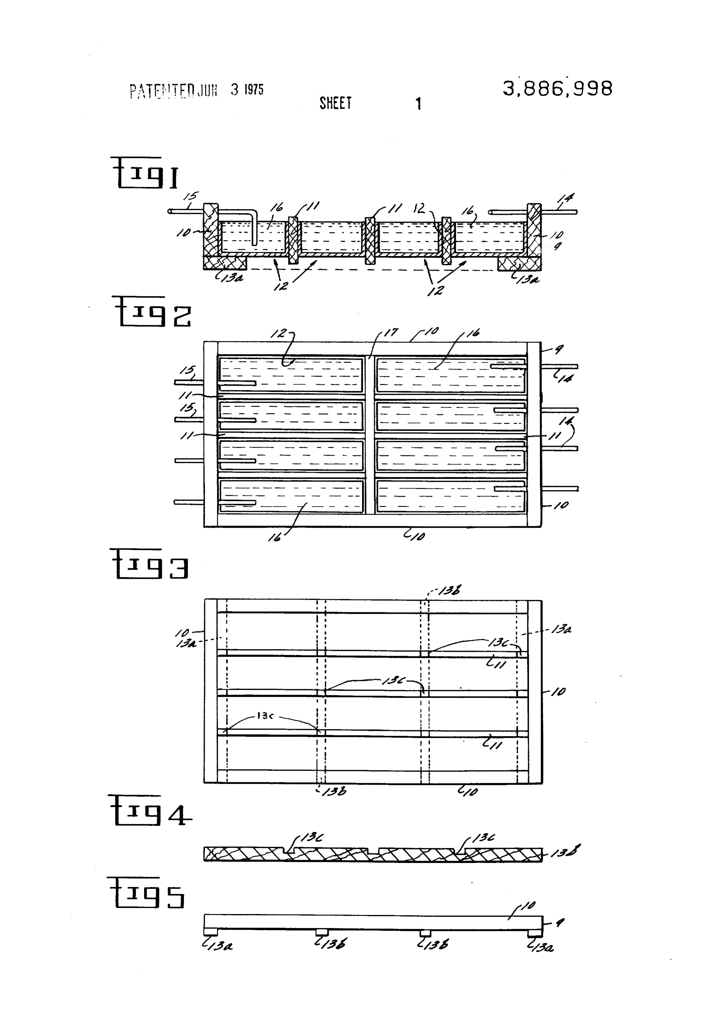
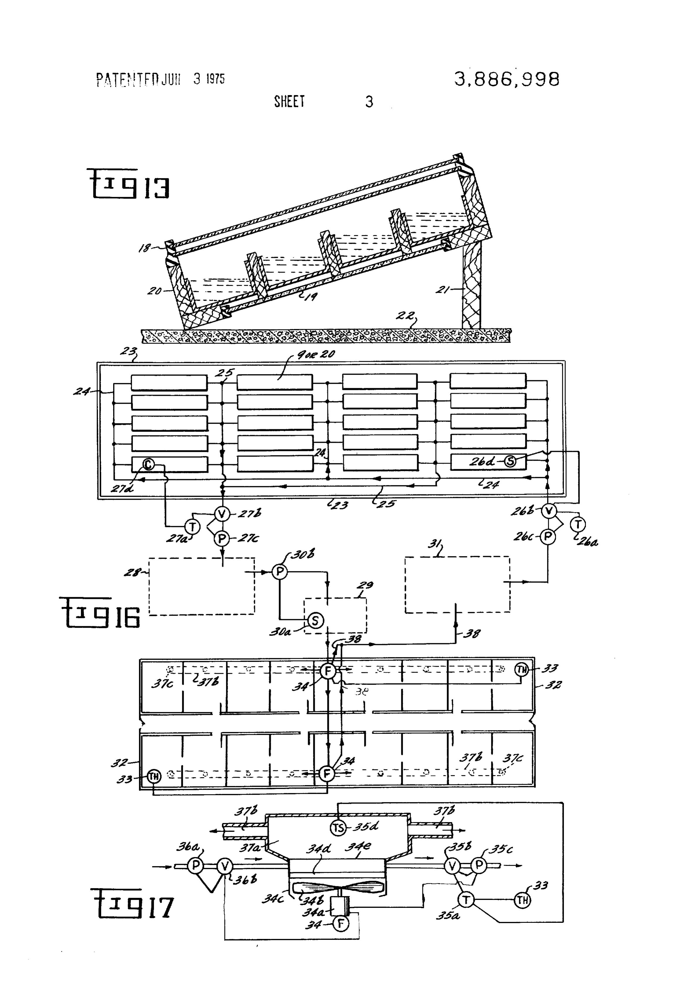
suck out all the water. Such an arrangement results in could be manufactured more cheaply and serve the the savings of several dollars on every unit that is built. same purpose as the others. The above and other objects and features of this in FG. 16 is a schematic view showing a group of com vention will be apparent to those skilled in the art to bination solar water heaters and chillers enclosed which this invention pertains from the following de within a fenced area that will furnish heating and cool tailed description and the drawings, in which: ing for an adjoining office building, also shown are FIG. 1 is a view in section of a solar water chiller, or three water storage tanks which are buried in the basic structure, showing a bank of four narrow and ground and which store or re-handle the hot or chilled shallow aluminum pans contained within wood sup water. Automatic controls are provided to fill and drain porting members, and having means of filling the () the heaters and chillers and to pump and re-cycle the chiller with water and emptying it. water to the various storage tanks into the office build FIG. 2 is a schematic view of a solar water chiller, as 1ng.
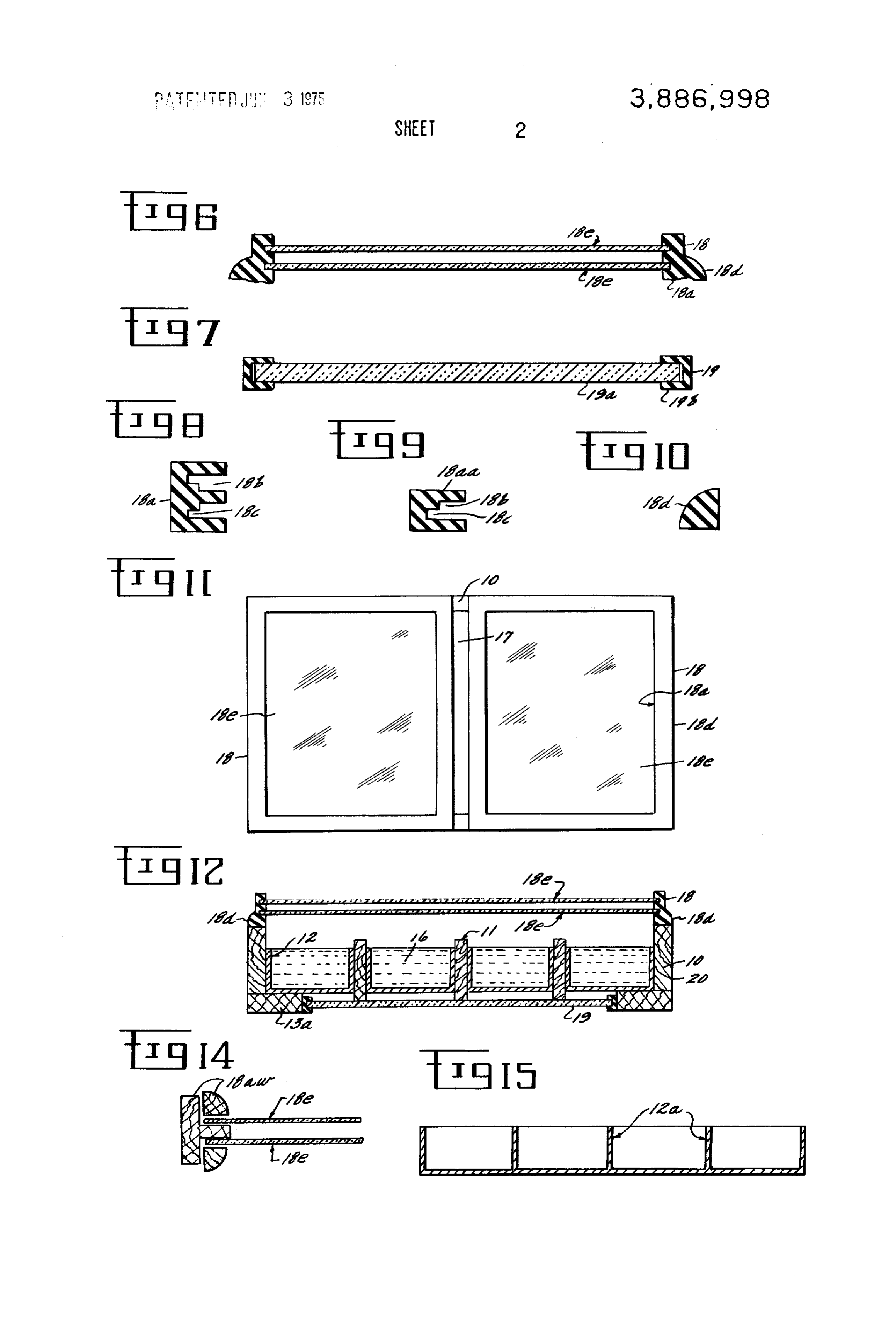
seen from the sky, showing an arrangement of narrow FIG. 17 is an enlarged view showing the fan unit, lo pans contained within wood supporting members, and cated in the mechanical room of the office building, its having means of filling and emptying the chiller. components, controls, and duct work which could not FIG. 3 is a schematic view of the wood structural be shown in FG, 16.
frame for the chiller, showing the wood exterior frame, In the following detailed description and the draw wood dividers, and bottom supports which are routed ings, like reference characters indicate like parts. out so the wood dividers can slip into them and be held 20 In FIGS. 1 through 5 is shown how a solar water firmly in place. chiller 9 is constructed so it can serve as a basic struc FIG. 4 is a view in section of one of the four wood ture for a combination solar water heater and chiller. bottom supports, showing how it is routed out to hold In FIGS. 1, 2, 3, and 5 is shown a 2 inches X 4 inches the wood dividers in place, while at the same time brac wood member which forms the exterior frame 10 of the ing the entire exterior frame to which it is fastened. 25 chiller 9, providing the structural strength to support FIG. 5 is a view in front or rear elevation depicting 8/3 pounds of water per square foot of chiller area, the exterior appearance of the chiller, lengthwise, and which would amount to approximately 125 pounds of showing the four wood bottom supports attached to the water in a chiller whose size is 2 feet by 8 foot. wood exterior frame of the chiller. In FIGS. 1, 2, and 3 are shown wood dividers 11 FIG. 6 is a view in section of the double-glazed glass 30 which serve as a structural support for four thin gage, panel which will be added to the top of the chiller to narrow, shallow and uncovered aluminum pans 12 shown in FIG. 1. In FIGS. 1, 3, 4, and 5 are shown wood convert it into a solar water heater.
FIG. 7 is a view in side elevation showing the insulat bottom supports 13a and 13b which brace the alumi ing panel which will be added to the bottom of the num pans 12 from the bottom and which are provided chiller to convert it into a solar water heater. 35 with routed out groove 13c which permit wood dividers
FIG. 8 is a view in section showing an extruded rub 11 to be slipped into them and be held firmly in place. ber gasket having two rabbets to provide for double Groove 13c, shown in FIG. 4 only as a feature of bot glazing, which will serve as the window frame for the ture of both 13b, tom-support is also shown in FIG. 3, and is a fea bottom-supports 13a and 13b. The four solar water heater.
FIG. 9 is a view in section showing an extruded rub running into them so they can behave
ber gasket having only a single rabbet, which will pro on the opposite side of the chiller 9 is awith filled water 16;
drain pipe 15 vide for single glazing if such a glass panel is desire. so water 16 can be removed after it is either heated or FIG. 10 is a view in section showing a flexible rubber moulding which will be glued both to the extruded rub chilled. Inso FIG. 1 is shown how drain pipe 15 is con ber gasket and the upper portion of the wood exterior 45 Structed that water 16 can be drained out of all the pans by a suction pump, thus eliminating the necessity frame to prevent heat losses from the solar water of welding a pipe to the bottom of the pans to accom heater.
FIG 11 is a schematic view of two glass panels, as minumdrainage.
plish Pan 12 will be made from thin gage alu sheet or coil that contains 2% silicon and 1% seen from the sky, that are glued to the upper portion of the exterior wood frame of the chiller and to a wood 50 manganese alloyed with it, so the light shiny metal will top-support which runs through the center of the turn black as described in my U.S. Pat. No. 3,314,414. FIG. 2 shows top-support 17 which is fastened to divid chiller.
FIG. 12 is a view in section showing a solar water ers 11 and wood frame 10, thus serving as a brace for heater which was transformed from a chiller by adding 55 centermembers these and also serving as a foundation in the a glass panel to the top and an insulating panel to the ber window frame 18upon of the chiller that which can be mounted rub
bottom. 12, and 13.
FIG. 13 is a schematic view in section showing how In FIGS. 6 and 7 are shown the glass panel 18 and in a solar water heater can be set on the ground and tilted sulating panel 19 which will be added to the basic struc to face toward the Sun, thus permitting the maximum 60 ture (water chiller 9) to convert it into a combination amount of sunlight to enter it. Solar water heater and chiller. When these two panels FIG. 14 is a view in section of a wood window frame are added to the water chiller 9, it becomes a solar designed for double glazing, which could replace the water heater 20 as shown in FIGS. 12 and 13. Glass extruded rubber gasket if it could be manufactured and panel 18 is comprised of an extruded rubber gasket glazed more cheaply. 65 18a, a flexible rubber moulding 18d, and glass sheets FIG. 15 is a view in section of a bank of four alumi 18e. Insulating panel 19 is comprised of a sheet of rigid num extruded pans, which could replace the singlely boardform insulation 19a such as styrofoam, eure formed pans and wood dividers if the extruded article thane, or fiberglass, which will be slipped into a chan
Page 7
nel-type metal frame 19h that will be fastened to the losses; therefore, plastics or any other type of transpar bottom of water chiller 9. ent panel could be used to replace glass if costs war FIGS. 8, 9, 10, and 11 show a detailed configuration ranted it.
of extruded rubber glazing gasket 18a and 18aa, and FIG. 16 shows a group of combination solar water flexible rubber moulding 18d, and how they are assem chillers 9 or water heaters 20 enclosed within a fenced bled together with glass sheets 18e to form glass panel area 23; only a few devices are shown on the drawing, 18. In FIG. 8 is shown extruded rubber gasket 18a but under field conditions as many as a thousand might which is designed for double glazing; it has two rabbets be so enclosed. The chillers 9 or water heaters 20 will 18b, each of which accept a single sheet of glass 18e; be filled with water by supply pipe 24, and emptied of at the base of each rabbet 18b, there is a deeper recess O water by drain pipe 25. Automatic controls will be used 18c, which is provided to help in the glazing by making to fill and drain the solar devices and to assure that the it easier to bend the rubber gasket 8a outward so the maximum amount of water will be heated or chilled glass 18e will slip into the rabbet 18b much more easily. within a day's time; to accomplish this, adjustable tim In FIG. 9 is shown extruded rubber gasket 18aa which ers will be used to control the flow of water into and out is designed for single glazing; it has only one rabbet 5 of the solar devices at specific periods during the day 18b, and at the base there is a deeper recess 18c. In or night, as this will permit several batches of heated or FIG. 10 is shown flexible rubber moulding 18d, which chilled water to be made; and this batching system has acts as a weather stripping around the base of glass been proven to provide the maximum BTU's of energy panel 18 to prevent heat from escaping. FIG. 11 gives within a day's time. No specific temperatures are a view of two glass panels 18 which are glued with rub sought, except that on the drain line a temperature con ber cement to the upper portion of exterior frame 10 trol will be located in one master water heater or and top-support 17; glass sheets 18e are fitted into ex chiller, so that on cloudy or rainey days in winter, or on truded rubber gasket 18a; and flexible rubber moulding extremely hot nights during summer, no hot or cold 18d is glued with rubber cement to both the wood water will be drained into the storage tank that is unfit frame 10 and the rubber gasket 18a. A liquid glazing 25 for use; through experience, it will be possible to pre compound 18f (not shown on the drawings) will be set the timers for a long enough period to yield 120°F used to seal the glass sheets 18e to the rubber gasket to 145F temperatures throughout the year. To provide 18a. for ample storage of energy in the form of hot or chilled FIGS. 12 and 13 show a solar water heater 20, which water, two large tanks and one small tank will be pro was created by adding glass panel 18 and insulating vided. Heated or chilled water will be drained into a panel 19 to the water chiller 9 shown in FIG. 1. All the large water storage tank, hereinafter called energy stor components of the water chiller 9 now serve to help age tank 28, capable of holding 25,000 to 100,000 gal heat water by sunlight; as the Sun shines through the lons of energized water, so that a large group of homes glass panel 18, its infrared rays are absorbed by the 35 in a subdivision or a large commercial building can be black color which has been oxidized on the shallow, made comfortable in winter and summer; after this narrow, thin gage aluminum pan 12, the wood frame heated or chilled water has been used to accomplish its 10, wood dividers 11, and bottom supports 13a and 13b purpose, the water will be re-cycled to another large brace the aluminum pans 12 so they can hold their storage tank, hereinafter called de-energized water shape and contain the water 16. Insulating panel 19 and storage tank 31 for re-use in the system; a small tank glass panel 18 help prevent heat losses from the solar 40 29 will be connected to energy storage tank 28 contain water heater 20. FIG. 13 shows how the solar water ing the heated or chilled water, and its purpose will be heater 20 can be tilted toward the Sun in winter when to act as a temporary storage near the building so that it is far off in the southern skies; this is accomplished the heated or chilled water will not be standing in pip merely by placing a wood block 21 under the bottom 45 ing where it will dissipate all its energy into the ground support 13a; the front portion of the water heater 20 instead of into the buildings. FIG. 16 also shows an of will rest directly on the earth 22. FIG. 13 clearly illus fice building 32 having several offices to be heated and trates the practicality of narrow aluminum pans 12 that cooled. The comfort system for the building will consist was designed for the water heater 20; if only one wide of a fan-unit and automatic controls, which will supply pan were used to cover the entire bottom and sides of 50 hot or cold water to the fan-unit and periodically drain the water heater 20, little water could be held in it be or re-fill it so that a continuous flow of hot or cold air cause the steep pitch would make it overflow at the can be made by the fan-unit and be distributed to the lower end; but, as designed, about three times as much offices by an air duct system.
water can be exposed to sunlight, and more energy can FIG. 16 shows how the chiller 9 or water heaters 20 be collected. will be automatically filled and drained through the use It is the intent of this invention that other materials 55 of automatic controls. A valve 26b and a pump 26c are could be used to make the combination solar water installed in the main trunk line of supply pipe 24, thus heater and chiller so long as they duplicate the general making it possible to fill all the solar devices within design shown on the drawings. FIG. 14 shows a wood fenced area 24 through the use of one pump and one frame 18aw which could be used to replace extruded 60 valve. Timer 26a will be connected to both valve 26b rubber gasket 18.a. FIG. 15 shows how aluminum could and pump 26c, and, depending upon the season, will be be extruded to match the general design of the narrow set to pump in new water from de-energized water stor pan 12; the extruded combination of pans 12a would age tank 31 twice to several times a day or night. When eliminate the wood dividers 11 and the routing of the the chillers 9 or water heaters 20 are filled, a float grooves 13c in bottom support 13a and 13b. In solar 65 Switch 26d, located in one master solar unit, will close tests conducted this summer, plastic was used as a valve 26b and shut off pump 20c. Next, the water in all transparent panel to cover the top of solar collectors, the solar devices will be either heated or cooled, de and they served just as well as glass in preventing heat pending upon the season, after this has been accom
Page 8
plished, timer 27a will open valve 27b and start suction the solar devices in the fenced area 33, where it will be pump 27c, which will remove all the heated or chilled heated or chilled, depending upon the season of the water from the solar devices through drain pipe 25, and year.
pump it into energy storage tank 28. If it is winter, tim Having described my invention, what I claim as new ers 26a and 27a will be set to fill and drain the solar de and desire to secure by Letters Patent, is: vices about twice a day, starting with one batch around 1. A method for heating, cooling, and handling water 9 o'clock in the morning, draining it around noon, put to make buildings comfortable throughout the year by ting in a second batch shortly after noon, and draining cmploying a semi-stationary basic structure to cool wa it again around 4 o'clock in the afternoon. If it is sum ter, and, seasonally, adding extra pieces of material s() mertime, timers 26a and 27a will be set to fill and drain the basic structure can serve to heat water, comprising, the solar devices at two hour intervals; and each time in combination, affixing within supporting members a the temperature of the water will reach 45°F to 65°F or bank of narrow and shallow and uncovered containers whatever the night temperature happens to be, if it is that act as the basic structure to chill water during sum cloudy or rainy or snowing in winter or if it is too hot mer, and employing the same basic structure with a in summer and one of the batches is not brought to a transparent panel and insulating cover added to the top useable temperature, temperature sensor 27d, located and bottom respectively to heat water during winter, in one master solar unit, will not permit timer 27a to suspending or tilting said uncovered containers so the function until the designated temperature is achieved. top and bottom are completely surrounded by cool FIGS. 16 and 17 show how the office building 32 will summer night air and thus chilling it, tilting said cov be heated and cooled through the use of automatic ered containers to face toward the Sun in winter so as controls. Hot or cold water will remain in the energy to heat water, periodically filling and emptying said storage tank 28 until the thermostat 33 in the office containers by automatically controlling the flow of building 32 calls out for heating or cooling. Thermostat water into and out of them through piping that does not 33 is tied-in with fan unit 34 and all the controls which pierce the bottom or lower portion of said containers, move energized water into the radiator 34e and out into said emptying occurring through syphoning or suction, de-energized storage tank 31; it also controls, indi storing said heated or chilled water until needed, peri rectly, pump 30b, which takes water out of energy stor odically pumping said heated or chilled water into a ra age tank 28 and pumps it into small storage tank 29; a diator that is interjected in an air duct system installed float switch 30a in small storage tank 29 starts pump in the buildings, blowing air through the radiator and 30b after pump 36b has nearly emptied small storage 30 causing heat or cold to flow into the rooms of the build tank 29 by moving energized water into radiator 34e. ings, said pumping and blowing being controlled auto It is estimated that to cool office building 32, which, let matically, removing the de-energized water to a storage us say, is a structure of 35,000 square feet, that 9,000 area, and periodically throughout the day or night mov gallons of chilled water per hour will have to be ing energized and de-energized water in an endless pumped through fan unit 34, which is comprised of a 35 cycle between the buildings and the various storage motor 34a, a fan 34b, a fan shroud 34c, a filter 34d, and areas and a fenced area containing large numbers of a radiator 34e; this means that the radiator 34e would said combination solar structures. have to be quite large and that, actually, several of 2. A method for heating and cooling a group of build them would be required to dissipate the chill in 9,000 ings comprising, in combination, alternately by season, gallons of cooled water every hour of a summer day; it 40 adding and removing a few materials from a basic also means that frequent changes of water will be re quired each hour. Such an undertaking will be accom structure so that by interchanging materials two differ plished in the following fashion: - as long as the tem exposing itphenomina ent solar result, one which chills water by to cool night air, the other heating water by perature set on the thermostat 33 is not satisfied, timer 45 exposing it to sunlight, enclosing a large number of said 35a will remain energized, and it will pass through one interchangeable structures within a fenced area, peri cycle after another; first, to open and shut valve 35b odically filling and draining said structures after water and start and stop pump 35c to drain all the water out has been heated or chilled to a satisfactory tempera of the radiators 34e, next, it will start motor 34a, which in turn will move fan 34b, which will blow air through 50 ture, storing said heated or chilled water, pumping said filter 34d and radiator 34e; almost simultaneously with throughorit chilled heated into a water into a radiator and blowing air duct system so as to heat or cool all the starting of the fan unit 34, timer 35a will open valve the rooms of the buildings, storing the de-energized wa 36b, and start pump 36a, which will pump chilled water ter, chilling said water by using an interchangeable from small storage tank 29 into radiator 34e; when this solar structure comprised basically of a bank of narrow has been accomplished, the timer cycle will automati and cally close valve 36b and stop pump 36a. The fan unit Solarshallow and uncovered containers, modifying said structure seasonally and alternately by applying a 34 will take perhaps a minute to dissipate all the chill transparent panel to the top and an insulating cover to in the water up into the plenum 37a, from thence into the bottom so as to seal it tight and prevent heat losses ducts 37b, and finally out into the offices through dif fuser 37c. At this point, timer 35a will start passing while exposing water to sunlight, said pumping of water and blowing of air being accomplished periodically by through another cycle such as described above; this will automatically controlling their flow by using control occur when a temperature sensor 35d, located in the devices and related equipment.
plenum 37a, says that the air passing by it is too warm;
and will then energize the timer 35a, so it will start its so3.asA tomethod provide for heating, cooling, and handling water year-round comfort for a group of cycle. Water is now removed from the radiator 34e, as 65 buildings, comprising, in combination, installing within described above, and passes through drain pipes 38 a fenced area what is basically a group of chillers com into de-energized storage tank 31, where it will remain prised of a bank of narrow and shallow and uncovered until the next day or night when it will be pumped into containers, tilting or suspending said chillers so they

Page 9
will be surrounded on the top and bottom by cool night ing the above cycles so that the buildings will always re air which causes the water temperature to drop to that main comfortable.
of the atmosphere, seasonally adding an insulating 4. A combination solar water heating and chilling ap transparent panel to the top and an insulating panel to paratus that can be used to keep buildings comfortable the bottom of said chillers, then alternately removing throughout the year, which is comprised of a semi and adding said panels with each passing season so that stationary basic structure that is essentially a water by the interchange of materials water can also be chiller and which can be converted into a water heater heated by exposing it to sunlight, periodically filling by adding an insulating transparent panel to the top and and emptying and storing the hot or cold water made an insulating cover to the bottom, said water chiller in said fenced area and pumping it into radiators that being comprised of a bank of thin gauge, narrow, shal are centrally located within an air duct system in the low, and uncovered metal pans which are held within buildings to be heated or cooled, blowing air through an open-type supporting structure, said water heater the radiators and forcing hot or cold air through the being comprised of the same bank of metal pans and ducts out into all the rooms in the buildings, and com supporting structure as the chiller plus a transparent prising the following sequence of operations: periodi cover on the top and an insulating cover on the bottom, cally throughout the day or night pumping de said water chiller cooling water by exposing it to the energized water from a large storage tank especially chilly night air during summer, said water heater heat designated for such water within a closed cycle of ing water by exposing it to sunlight during winter, said equipment into said interchangeable solar structures by pans having a base and walls extending upwardly from using an automatic device which has been pre-set to au said base and an upper portion that is uncovered, tomatically open and close the piping and start and stop means for tilting or suspending said chiller so it will be a pump which moves said water through said piping surrounded on the top and bottom by chilly night air, from said large storage tank to said interchangeable means for resting said water heater on the ground and solar structures, placing a control device within one of 25 tilting it so it will face toward the sun, means for filling the interchangeable structures that closes the piping and emptying said combination apparatus automati and stops the pumping after said structures are filled, cally, means for enclosing a large group of said combi periodically throughout the day or night pumping ener nation solar water heaters and chillers in an outdoor gized water made in said interchangeable solar struc several area so it is possible to provide heating and cooling for tures into a large storage tank which is especially desig 30 buildings, means for automatically controlling nated for such water by using an automatic device the flow of water into and out of said group of devices which has been pre-set to open and close the piping and through the use of one set of automatic controls for fill start and stop a pump which moves said water through storinging them and one set for emptying them, means for energized and de-energized water, means for said piping from said interchangeable structures to said automatically storage tank, placing a control device within one of the 35 of controlling the flow of water into and out interchangeable structures which senses whether said use of only one to the buildings set be heated and cooled through the of automatic controls just before water is hot or cold enough and which either permits said water enters a radiator or delays the drainage of water from said interchange matic controls just after said and only one set of auto water leaves the radiator, able structures, installing a temperature control device within the buildings to be heated or cooled that auto 40 said radiator being the means of converting hot or cold water into hot or cold air, means for automatically con matically controls other automatic devices which con trolling a fan unit which blows hot or cold air through trol the flow of water and air through the buildings and air ducts connected to the radiator, means for continu comprising the following sequence of operations: peri ously supplying hot and cold water to the radiator by odically throughout the day or night pumping ener placing a temperature sensor in the plenum chamber gized water from said large storage tank into a small 45 that will control an automatic storage tank near the buildings by using a control de edly cycle water through the timer which will repeat radiator whenever the vice inside the small tank which starts a pump when temperature sensor says that the air is not hot or cold said tank is nearly empty, setting the main temperature enough, and means for automatically controlling all the control at a desired temperature for keeping the build automatic operations within the building heating and ings comfortable throughout the day and night and cooling system through the use of a thermostat which
connecting it to an automatic device which has been controls the temperature inside the buildings and which pre-set to automatically open and close the piping and instigates the continuous cycling or hot or cold water start and stop a set of pumps which brings energized and air through a central heating-cooling system. water to and carries de-energized water away from a 55 5. A combination solar water heater and chiller capa radiator that is centrally located in an air duct system ble of heating and cooling water that can be used to and which simultaneously runs a motor-fan unit which keep buildings comfortable throughout the year, which blows air through the radiator and air ducts and forces is comprised of a basic structure that consists of a bank hot or cold air into all the rooms of the buildings, in stalling a temperature sensing device in the plenum of 60 of thin gage, narrow, shallow, and uncovered aluminum pans which are held within a wood framework, said alu the air duct system and connecting it to the automatic minum being alloyed with silicon and manganese to device which is pre-set to automatically open and close make it turn black, said wood framework consisting of the piping and start and stop the pumps and run the fan an exterior frame, a series of dividers running longitudi unit which blows air through the radiator and duct sys nally with the pans, a top-support located centrally on tem so that all these devices continue to re-cycle until 65 top of said dividers, and a group of bottom-supports all the rooms in the buildings are heated or cooled to with grooves in them to secure the dividers, all said the temperature set on the main temperature control, members of the wood framework being fastened to one and repeatedly throughout the day and night continu another and spaced apart from one another so that the
Page 10
maximum amount of water and metal will be exposed structures and having a timer that has been pre-set to to the air on the top and bottom of said pans, means for periodically open a valve installed in the piping system filling and emptying said basic structure, said basic and starting a pump which moves said de-energized structure being fitted with drain piping and supply pip water into said basic structures and having a float ing which do not pierce the bottom or lower side walls switch in one master structure which closes said valve of said pans and with the drain piping protruding down and stops said pump after all said pans are filled with ward from the top to near the bottom of the pans so water, a second set of automatic controls which pumps said water can be removed through syphoning or by water from the basic structures into an energy storage suction, said basic structure being so designed that it tank and having a timer that has been pre-set to period can be converted into a solar water heater by adding an () ically open a valve and start a pump and having a tem insulating glass panel to the top and a fibrous or granu lar insulating cover to the bottom, said glass panel com perature sensor in one master structure which deter mines if the water is hot or cold enough and which ei prised of a flexible rubber moulding and an extruded ther permits or delays the drainage of water from all rubber gasket having two rabbets into which are fitted two sheets of glass, said rabbets having a deeper recess 15 said structures into said energy storage tank, said basic in one portion of their base which makes the gasket ing whichbeing structure fitted with drain piping and supply pip more plyable, means for fastening the glass panel to the walls of said pans,notandpierce does with the bottom or lower side the drain piping protruding basic structure, said fibrous or granular insulating downward from the top to near the bottom of said pans. cover consisting of a rigid board form type of insulation 9. A combination solar water heater and chiller hav which is fitted into a channel-type frame which is fas 20 ing the same features as the apparatus described in tened to the bottom-supports of said basic structure. claim 8, with the following features added: - means 6. A combination solar water heater and chiller simi lar to that described in claim 5 except that the extruded waterautomatically for from said controlling the flow of energized energy storage tank through the build rubber gasket will have only one rabbet into which is ing and back to said de-energized water storage tank
and repeating this cycle numerous times throughout 7. A combination solar water heater and chiller simi lar to that described in claim S except that the extruded the day or night so the buildings will be kept constantly rubber gasket will be replaced by a wood window frame comfortable, the flow of said means for automatically controlling energized water being a thermostat set at a provided with either a single glass stop or two glass stops which would be used for either single or double 30 temperature of approximately 75 Fahrenheit and lo cated at a suitable place in the buildings, said thermo glazing.
8. A combination solar water heater and chiller used stat being connected to a timer which is set to go for heating and cooling a group of buildings, wherein through a series of cycles so as to automatically control a large number of said combination solar devices are the flow of water and air through a system of piping and enclosed in a fenced area on the ground somewhere 35 air ducts, said timer cycle consisting of first opening a close to the buildings to be heated and cooled and with valve and starting a pump that removes de-energized means for handling and storing the great volume of en water from a radiator or radiators to said de-energized ergized water through the use of automatic controls, water storage tank and then closing said valve and stop said combination solar device being comprised of a ping said pump, and next almost simultaneously start basic structure which is essentially a water chiller con 40 ing a fan unit that blows air through said radiators out sisting of a bank of thin gage, narrow, shallow, and un into a duct system and then opening a valve and start covered pans which are formed either by a press or a ing a pump that moves energized water from a small break, or through extrusion and affixed to an open-type water storage tank into said radiators and then closing supporting structure so the pans can be surrounded on said valve and stopping said pump, said small water the top and bottom by chilly night air, said basic struc 45 storage tank having a float switch which starts a pump ture being designed so it can be converted into a water that draws energized water from said energy storage heater by adding a glass panel to the top and an insulat tank into said small water storage tank, said radiators ing cover to the bottom, said aluminum being alloyed being interjected into an air duct system that runs with silicon and manganese so the pans will turn black through the buildings to be heated or cooled, said air when exposed to sunlight and a mixture of salt water or 50 duct system having a plenum mounted above said radi fluoride, said glass panel being comprised of a flexible ators which distributes energized air into the duct sys moulding and an extruded rubber gasket having two tem, said plenum having a temperature sensor mounted rabbets into which are fitted two sheets of glass, said on its walls which is connected to said timer and which rabbets having a deeper recess in one portion of their starts said timer through another cycle when it senses base, means for fastening said glass panels and insulat 55 that the air passing through the plenum is not hot or ing cover to the basic structure, means for filling and cold enough, the above cycles and sequences being re emptying said combination solar devices which consists peated over and over again throughout the day as of a piping system into which has been interjected two called for by the thermostat, the timer, and the temper sets of automatic controls one of which pumps water ature Sensor.
from a de-energized water storage tank into the basic 60 ck k is a sk
Provenance
- Collection
- Cited prior art
- Original PDF
- patentimages.storage.googleapis.com →
- Filed
- 1973-09-06
- Pages
- 10
- Method
- pdftotext (the PDF's own text layer) + pdftoppm 300dpi page scans
- Source
- Google Patents bibliographic record
- Granted
- 1975-06-03
- Inventors
- Richard J Rowekamp
- Transcribed from
- patentimages.storage.googleapis.com →