patent · US3314862
Process and apparatus for solar distillation
18 April 1967
Page 1
Drawing sheet — no readable text.
Page 2
Drawing sheet — no readable text.
Page 3
Drawing sheet — no readable text.
Page 4
Drawing sheet — no readable text.
Page 5
Drawing sheet — no readable text.
Page 6
Drawing sheet — no readable text.
Page 7
United States Patent Office 3,314,862 Patented Apr. 18, 1967
3,314,862 It is additionally an object to utilize chemical heat PROCESS AND APPARATUS FOR SOLAR storage cells within a solar still and to improve the func DESTILLATION tioning of the chemical heat storage cells by using the Harold R. Hay, 795 Roble, Menlo Park, Calif. 94027
chemicalcondensate reservoir salts in their to maintain a portion of the solid state.
Yet another object is to provide a solar still adaptable
This application is a continuation-in-part of my prior to rough terrain without requiring expensive leveling and applications Ser. No. 668,202, filed June 26, 1957, and to provide a means for maintaining the distilland in a thin Ser. No. 163,381, now abandoned filed Dec. 19, 1961. O layer close to the cover of the still. - This invention relates to a process and apparatus for Other objects and advantages of the present invention solar distillation of saline or brackish water, alcohol, or will become more apparent after reading the following other liquids volatile at relatively low temperatures. description taken in conjunction with the drawings but it Despite recent engineering efforts, including elaborate is a final object to combine the various improvements field tests and computerized data, the designs of the comprising this invention so as to produce yields and 1870's have remained basically unaltered and have given l3 economies from said combination superior to those of the highest yield and the lowest cost potable water by prior art or to those obtainable with the several improve solar distillation. Efforts to add solar concentrators, con ments applied separately, and to allow for that flexibility densers, and multiple-effect distillation have proved to be in choice of a combination which will produce maximum uneconomic, owing to extra cost, additional space, and 20 benefit under various conditions of climate, land avail maintenance. Plastic-cover, air-inflated stills have not ability, feed-water supply, still capacity, and financial re proved satisfactory owing to adverse results of power Sources available for construction of the still, failure and thermal changes such as clouds or rain show
CTS. The invention is capable of receiving a variety of me chanical expressions, some of which are illustrated on the
It has become apparent that neither major equipment accompanying drawings, but it is to be expressly under additions external to the solar still, calling for forced re 25 stood that the drawings are for purposes of illustration circulation of air and vapors through insulated ducts, heat only, and are not to be construed as a definition of the exchangers, and the like, nor minor changes within the limits of the invention, reference being had to the ap still have altered the economics of production sufficiently pended claims for that purpose. - to be competitive with other processes for producing po 30 The following embodiments of the invention relate to table water. To meet this competitive cost, this invention an apparatus for distillation, hereinafter simply referred modifies several still components in novel ways, adds new to as a "still,” and to a distillation process. More spe principles and unifies these novel features into embodi which: cifically, these embodiments relate to a solar still in ments of higher efficiency than stills of prior art.
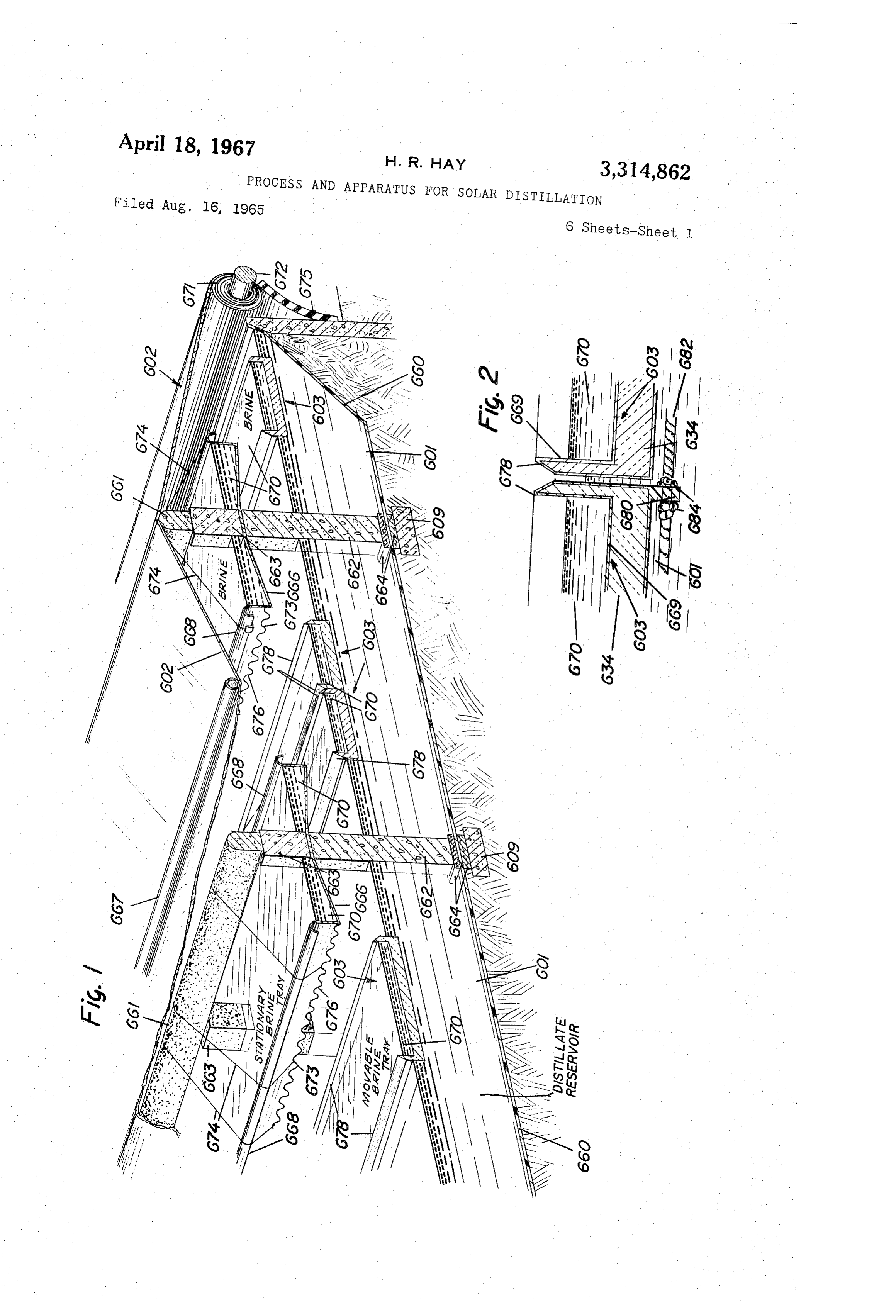
This invention has the following objects: FIGURE 1 is a partially cross sectional and partially It is one object of this invention to provide an improved 35 cut away view of a solar still embodiment with movable device of low cost for the distillation of liquids which will thermal barriers in the form of shallow basins confining result in more efficient use of available solar energy. distilland, the basins floating on a reservoir of the dis It is an object of the invention to provide a more aero tilate and with said movable thermal barrier basins illus dynamically stable plastic cover which is movable and trated in their daytime operating position. This figure which has reduced tendency for failure by abrasion, em 40 also illustrates rolling device. the use of a cover adjustable by means of a brittlement, tearing, or deflation.
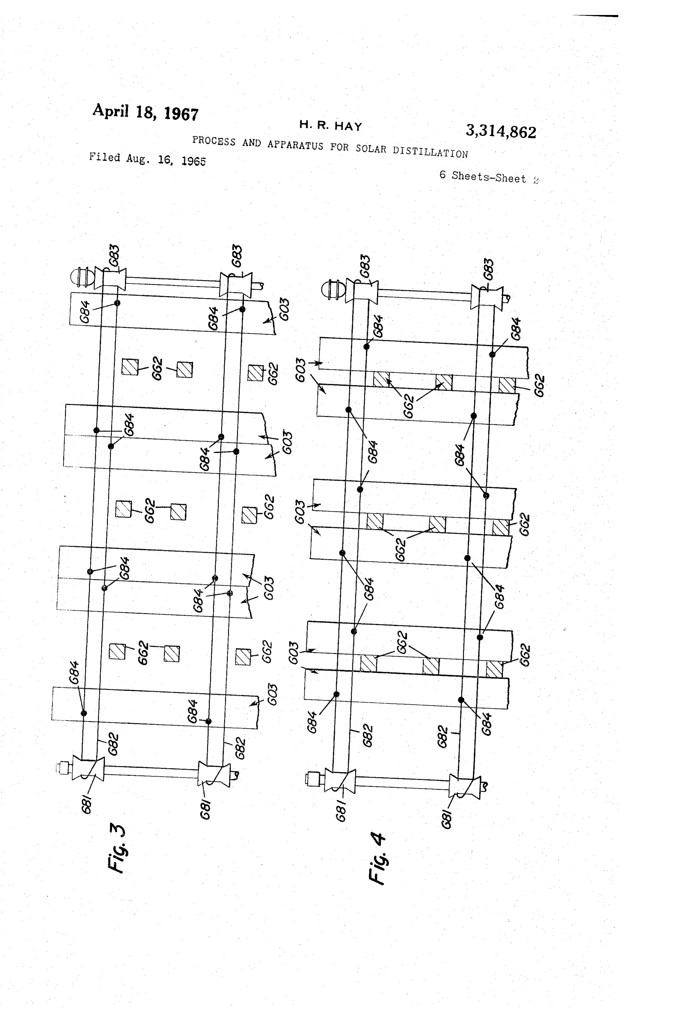
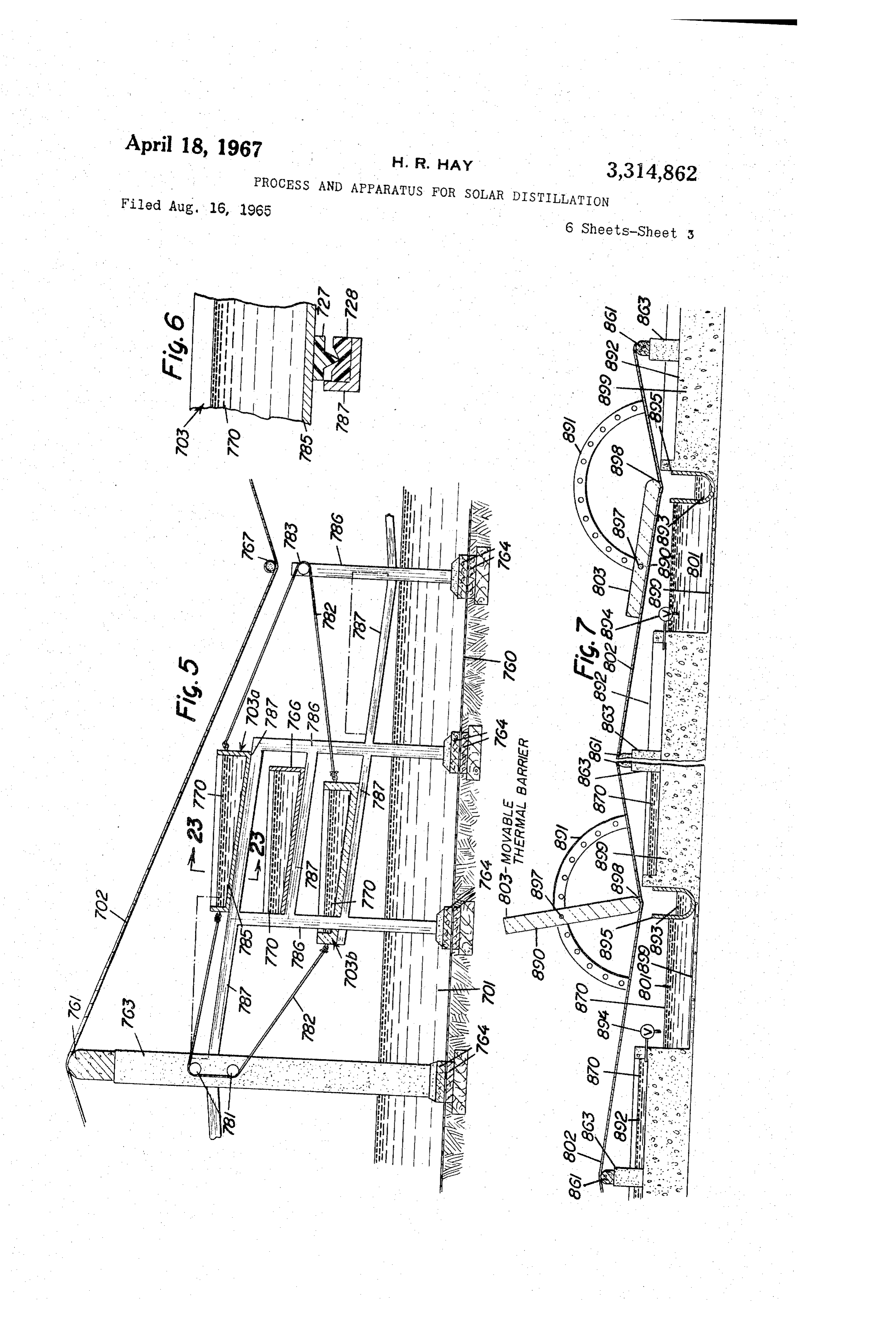
A further object is to provide a cover which reduces FIGURE 2 is an enlarged fragmentary cross sectional the re-evaporation of condensate formed thereon. view of two of the movable thermal barrier basins of Another object is to modify or eliminate the use of FIGURE 1 abutting in their daytime position. condensate collection troughs which have added to re 45 FIGURE 3 is a diagrammatic representation of one evaporation losses considerable of condensate and which have required means by which movable thermal barrier basins are posi maintenance. tioned in their daytime relationship shown in FIGURE 1. It is an added object to collect and retain the conden FiGURE 4 is a representation similar to FIGURE 3 sate in an internal reservoir thereby eliminating the need 50 which shows the movable thermal barrier basins shifted for an extra storage tank, piping, and pumping. from their daytime location shown in FIGURE 1 and It is moreover an object to utilize one or more con FIGURE 3 to their nighttime position adjacent to the con densate reservoirs as a condenser and in manners which crete columns supporting the stationary- basin and the will increase the yield of distilled water without the addi cover of the still, tion of complicated external devices. 55 FIGURE 5 is another embodiment in which the mov It is also an object to provide, overyling the condensate able thermal barrier basins are supported above the reser reservoir, brine basins which may be so positioned with voir of the distillate rather than floating upon it, and in respect to each other as to obtain multiple-effect distilla which the distilland basins contain chemical heat stor tion, to cool the condensate in the reservoir, to distribute age cells.
recirculated air and vapors, and to reduce heat losses. 60 FIGURE 6 is a cross sectional view of a portion of the It is an object to provide a movable thermal barrier inclined support and the movable thermal barrier basin within the solar still, or attached externally thereto, which taken along line 23-23 of FIGURE 5. maintains favorable thermal conditions within the still FIGURE 7 is another embodiment in which a mov thereby increasing the distillation efficiency. able thermal barrier means is externally located with re spect to the still.
Page 8
s which has caused condensate to drop back into the brine
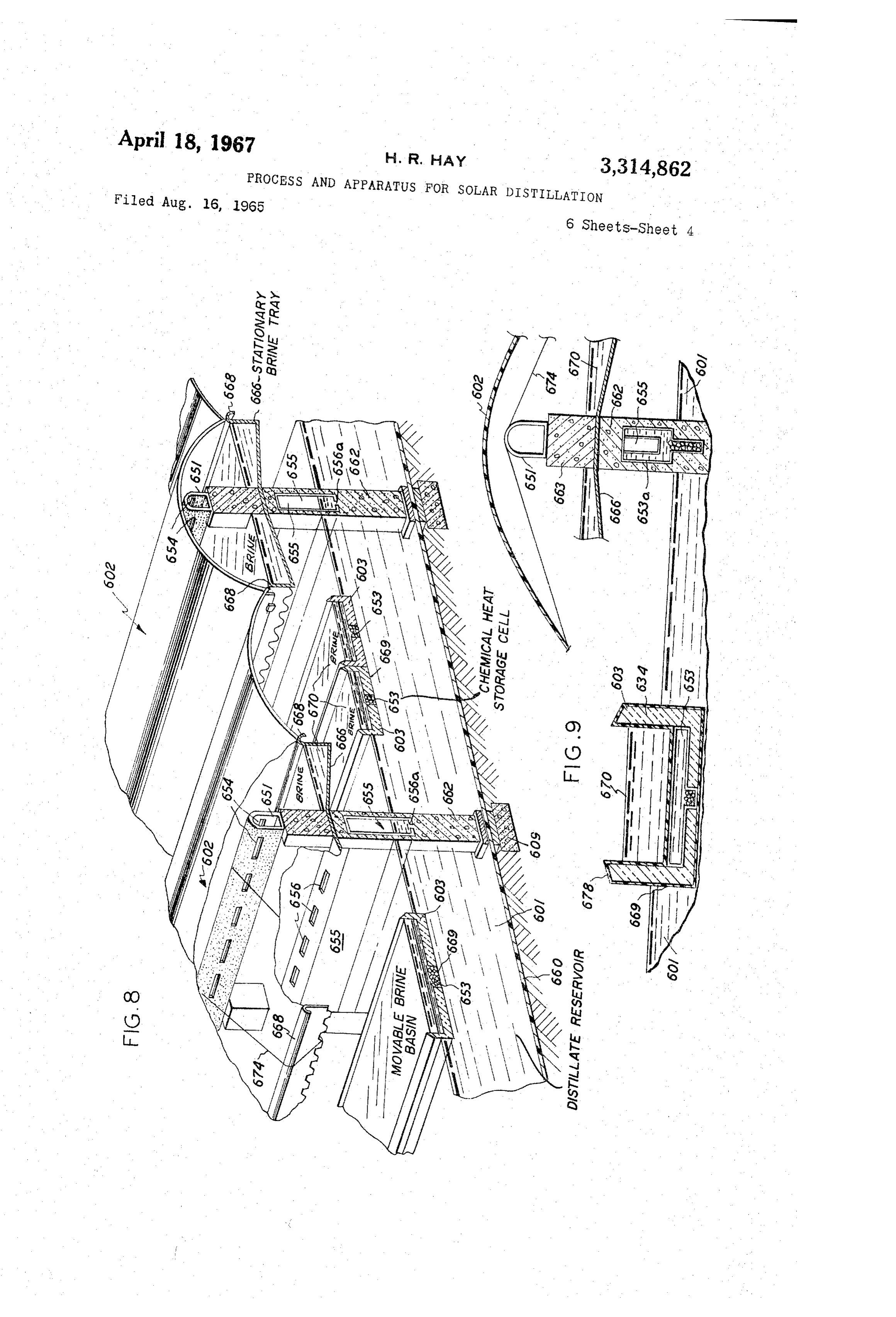
FIGURE 8 is a partially cross sectional and partially basin; and the cover has not sufficiently yielded to wind cut-away view of a solar still embodiment having mounted forces but has been torn thereby. These defects of plas on the stationary brine trays a cover supported by air tic covers have been serious with respect to air-inflated pressure introduced through a hollow lintel and partially 5 stills, particularly upon failure of the air-inflating means. exhausted through a separate conduit serving as a con Condensate collection troughs generally used in the denser; also, FIGURE 8 illustrates the use of chemical prior art are expensive to build and to maintain, are sub heat storage cells in the floating brine basins. ject to leakage and loss of condensate, tend to shade a FIGURE 9 is a partially cross sectional and partially portion of the saline water basin, and provide another cut-away view of the solar still of FIGURE 8 showing 10 Surface from which the condensate, already containing in more detail the chemical heat storage cell in the float a high sensible heat, is reevaporated. The distillate col ing brine basins and showing the addition of a chemical lected in these troughs is conducted to a sump from which heat storage cell in the conduit under the stationary brine itstallation is pumped to an external tank or reservoir. This in for pumping and storing adds to the initial tray.
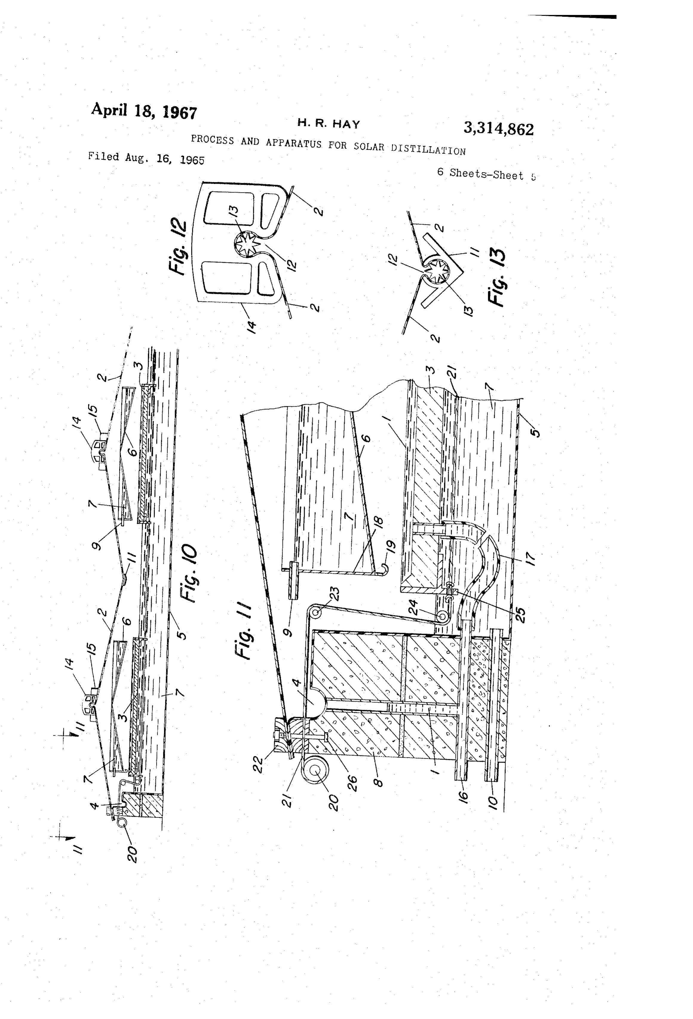
FIGURE 10 is a cross sectional view of a portion of a 5 investment, to the continued maintenance and to the land still having a bottom brine basin on which floats a dis requirement for the process.
tillate reservoir basin positionable over the bottom brine It has now been established that shallow brine basins basin and under a raised brine basin. with brine depth of two inches or less are the most effi FIGURE 11 is an enlarged cross sectional view of a cient, and pains are taken to level the still base to prevent high spots which will be dry. Dry spots are not only portion of the still of FIGURE 10. 20
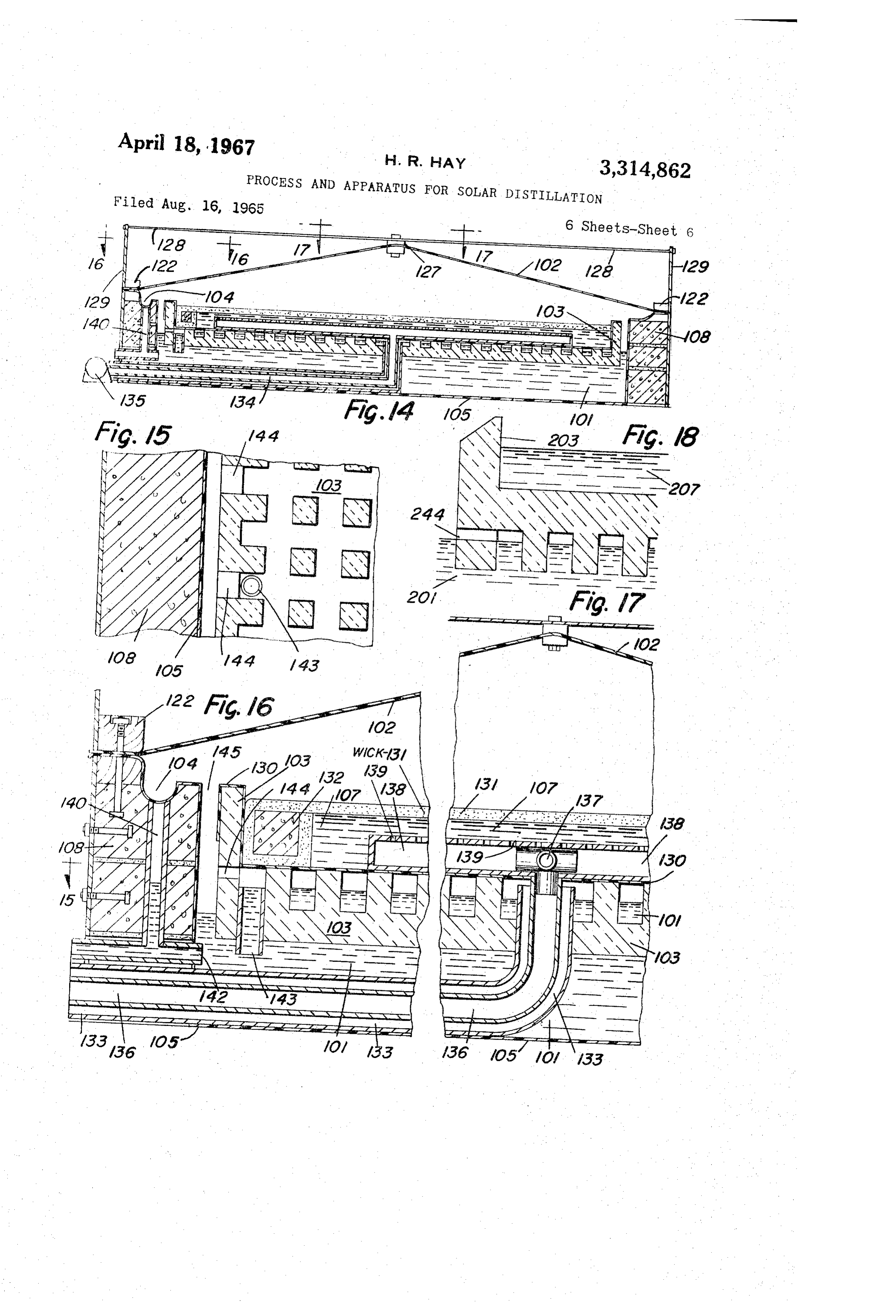
FIGURE 12 is a cross sectional view of a means for non-productive but cause "burn-outs” of some basin bot Supporting a solar still cover. toms and necessitate extensive repairs. Even on favor FIGURE 13 is a cross sectional view of a means for able sandy land, the cost of leveling prior to erecting a suspending a distillate collecting trough from the cover still may be 10 to 20 percent of the total installation costs. of a solar still. Less favorable terrain, particularly rocky areas, may make FIGURE 14 is a cross sectional view of a circular solar the installation of solar stills of prior art prohibitively still having forced recirculation of air and vapors be costly.
tween a plurality of Surfaces capable of condensing vapors, The Water produced by the solar stills of the prior art and having a floating basin with a patterned upper sur has left the stills at a relatively high temperature resulting face. in loss of the sensible heat, and therefore of some poten FIGURE 15 is a partial view through the patterned 30 tially useful energy, and supplying consumers with a less upper Surface of the floating basin of FIGURE 14. refreshing drink than if the water were nearer nighttime FIGURE 16 is an enlarged view of a peripheral portion temperature.
of the solar still illustrated in FIGURE 14. Many Sciar stills have used fixed insulating materials FIGURE 17 is an enlarged view of the central portion under or around the perimeter of the brine basins to pre of the solar still illustrated in FIGURE 14. vent heat loss. Such loss is relatively small as compared FIGURE 18 is a partial cross sectional view of a float to the great loss which results from re-radiation from the ing brine tray of the type in FIGURE 1 but with a pat basin Water through the cover. Table I, following, gives terned under Slirface adapting it for use in a system recir thermal efficiency and energy losses of a standard type culating air and vapor within a solar still. 40 Solar still and is reproduced from an article by Joseph J. Solar stills used for saline water distiliation in the prior Strobel, Chief, Division of Processes Development, Office art have consisted basically of four elements: a closed of Saline Water, United States Department of Interior. structure with a transparent portion which allows the entrance of solar radiation; a basin or tray to confine the Table I.-Distribution of Solar Energy in the Evaporation Saline water; a condensing surface which is usually the of Water cover or wall of the still, though in some forms it may Distribution of solar radiation: Percentage be located externally; and a distillate collecting system (a) Evaporation of distiilate (efficiency) --- 32 which is usually a collecting trough connected by piping (b) Ground and edge heat losses ---------- 2 to externally located distillate storage facilities. (c) Solar radiation reflected from still ------ 11 The general use of the still cover both as an entrance (d) Solar radiation absorbed by cover - 4.5 for Solar energy required to evaporate water and as an (e) Radiation from basin water to cover ----- 26 exit for latent heat released by condensing water vapors (f) Internal convection ------------------ 8 during the hours of high solar radiation obviously is (g) Re-evaporation of distillate and unac Working at cross purpopes. Much incoming energy is counted for losses -------------------- 16.5 consumed in re-evaporating condensate and does not penetrate to the saline water in the brine basin. It is 100.0 reported that in excess of 10 percent of the condensate is so re-distilled either from the cover or from the col Table I clearly shows that the radiation and re-evapora lecting troughs. tion losses referred to above are of major proportions and Condensation on the cover also causes reflection of 60 result in the low 32 percent efficiency typical of basin Solar radiation. This reflection loss to the atmosphere type stills. Anything which reduces these losses will in is especially great when using plastic film covers which crease still efficiency and reduce the area which must be tend to cause drop condensation rather that the film covered to produce a given volume of distillate. The condensation obtained with a glass cover. Special treat very large land requirement for solar distillation by the ments of the plastic surface to eliminate the drop con prior art constitutes a major obstacle to the use of solar densation are not perfected and add materially to the energy for saline water recovery.
cost of the plastic cover of the still. In the present embodiment of this invention, it is pos Glass covers on solar stills are costly; they limit the sible by means of a movable thermal barrier to operate a distance from the valley to the ridge of basin stills; they Solar still So as to eliminate or minimize many of the have numerous joints needing special treatment to reduce above-mentioned disadvantages of the prior art and there excessive vapor leakage; and breakage from hail or wind by to obtain a much higher production efficiency and is not only irreparable but causes damage as well to pre lower distillate cost.
ferred still bottoms. Plastic covers, as used in prior art, FiGURE 1 illustrates a solar still which consists of an have required many fastening points at which stresses are enclosure having an exterior surface a first portion of non-uniform thereby causing chafing, abrasion, and em 75 which is a material having high thermal storage charac brittlement; large covers have had excessive wind-flutter
Page 9
teristics in the form of a reservoir of water 601, this being 6 the collected distillate of the distillation process a sub such as polypropylene, or of metal films, such as copper stantial portion of which is retained within the still for its or aluminum foil, or of sheets of rubber and the like, or heat capacity effects. FIGURE 7 shows the concrete of thicker mats of asphalt or asphalt impregnated mate base 899 of a still which would also correspond to a first rials, or of sheets of sprayed-in-place foamed plastics, or portion of high thermal storage characteristics though in the base can be made of heavier concrete construction 899 this case the brine to be distilled and the ground below as is shown in FIGURE 7. In all instances, the edges of the still may be so considered as well. the base materials are raised or sealed at the perimeter of The second portion of said enclosure of FIGURE 1 is the still to form a reservoir capable of containing high the cover 602 which should preferably be transparent or heat capacity liquid 60 which is here described as dis translucent and may consist of glass, plastic film, or other O tillate water but which may be any other distillable mate material capable of transmitting solar energy. The cover rial, such as alcohol, having a sufficiently high vapor pres may be a plurality of sheets of such materials and it may sure. Also the still may be used for objectives other than be a combination of them. Available plastic films of for the recovery of the distillate, as for instance, the con excellent solar energy transmitting characteristics are centrating of sugar or salt solutions. polyvinylfluoride, polytetrafluoroethylene, polychlorotri The cover 602 of the still is supported by a plurality fluoroethylene, polyglycolterephthalate and other types. of lintels 661 running the full width of the still in parallel This element of the enclosure has low thermal storage rows (e.g., about eight feet apart in the present embodi and high heat transfer characteristics thinness of the cover material used.
by virtue of the ment). Lintels 66 are supported by spaced columns 20 662 which also support stationary brine tray 666, which
The third major element of this embodiment is mov will be described later. The weight, supported by able thermal barrier 603 of FIGURE 1. In this instance, columns 662, bears onto protective pads 664 on both sides the thermal barrier serves as a basin to contain saline of impermeable base 660 thereby preventing the base water (hereafter referred to as brine or as the distilland). from being ruptured by sharp column edges or by the This movable thermal barrier is preferably composed of excessive loading from columns 662. A footing or foun low density and lightweight materials having low heat dation. 609 distributes the loading from columns 662 to capacity and low thermal transfer characteristics. The the ground under the still, In other embodiments the thermal barrier may be of the rigid closed-cell type such columns can be avoided by suspending the lintels and as cork, foamed glass, or some forms of foamed poly trays across the width of the still on the supporting side styrene or it may be of the semi-rigid type of open-cell 30 walls as in FIGURE 10.
foamed polyurethane. Mineral wool, glass fiber, or wood Lintels 661 may be of reinforced or prestressed con fiber batts confined within a suitable material may be used crete, or of corrosion resistant metals such as aluminum or aluminum foil, plastic sheets with vacuum deposited alloy No. 5086, or of decay resistant wood such as the metal surface, a painted surface, or other reflective in heart portion of redwood. Columns 662 and footings sulation alone or in combination with other insulators 35 609 may be of concrete blocks, brick masonry, or of any may be used. In a solar still, the movable thermal barrier material suitable for the lintels. If wood footings are means may consist in part of the distilland either sup used they should be chemically preserved. It is advisable ported on an insulating material or supported on a non also to treat the ground under the still with a herbicide insulating material. As shown in FIGURE 1, movable to prevent plant growth from rupturing impermeable thermal barrier basin 603 is all or in part low density 40 base 660. The column pads 664 may be made of rubber, insulation which facilitates the movement of the basin fiber, asphaltic materials, cork, plastic, or of any mate by causing it to float on the surface of reservoir of dis rial inherently or compounded to be resistant to flow tillate 601. In other cases, as in FIGURE 5, some of under660.continued loading and capable of protecting base the movable thermal barrier basins 703b are insulated while others 703a may not be insulated but depend in The cover 602 can be fastened to its supporting lintels stead upon the thermal storage characteristics of the brine is661allowed but in the embodiment illustrated in FIGURE 1, it to drape over rounded lintels 661 and is caused contained therein to function as a thermal barrier within the meaning of the invention. As will be described later, 67 to assume the angular roof shape by applying a weight these brine basins may be integrated with chemical heat which is sufficiently heavy to produce the desired storage cells 753a and 753b. Obviously other high heat 50 shape but not so heavy as to cause excessive elongation capacity materials suitable for distillation can also retard be or fatigue in the film cover 602. The weight which can an external energy source from heating the portion 601 supported varies with cover composition and thick which is also of high heat capacity. In another embodi ness. If needed, an additional thickness of the cover ment, as shown in FIGURE 7, the movable thermal bar of material 602 may be applied to the film cover by means Tier is mounted external to the still and differs from the heat sealing or by adhesives to add strength at the corresponding thermal barriers of embodiments illustrated 667; ridge over lintels 651 or at the valleys under weights in FIGURES 1 and 5 by virtue of functioning as a part reducethey stormwould also provide tear stops which would damage.
of a still without being a basin confining distilland.
In addition to the three major components mentioned, The weights 67 are represented as plastic tubes filled with Sand or other material of suitable density and these the still of FIGURE 1 consists of plastic sheet 660 under 60 Weights lying the still and providing an impermeable base to sup preferably extend the full width of the still. port and retain the internal reservoir of accumulated dis the Under certain circumstances, it may be desirable to use tillate 601. Owing to the overlying brine trays of the em plastic tubes as conduits for the distilland which bodiment shown in FIGURE 1, the still bottom is shaded would then become preheated in the daytime and could from actinic rays during the daytime. Moreover, it is be used as make-up for the distillation process. Round normally covered with a layer of water at a temperature metal bars or other rigid materials could be used as lower than that of the evaporating brine hence it can be Weights 67 and said rigid bars could be attached, exter of less durable, and less expensive, material than that nally to the still, to an actuating means which causes needed in solar stills of the prior art. Thin, low-cost them to move horizontally parallel to the base of the polyethylene film may be used for the impermeable base 70 still, between the columns and lintels supporting cover resting directly on relatively unleveled ground and said 602. Such sideways movement will, of course, change polyethylene may be heat-sealed or sealed by suitable the angles which the cover makes both to the still base adhesives to form a base of unlimited size. It is equally and to the source of radiant energy such as the sun so possible to make impermeable base 660 of other plastics 75 mum that the angle of incidence remains favorable to maxi absorption.
Page 10
by corrugations 673. Lips and corrugations are well
Flexible materials are preferred as cover weights 667 recognized means for maximizing strength of thin section in some embodiments of the invention since one purpose trays made by molding or spraying processes. If such of draping cover 602 over intels 661 by means of weights modifications in shape of tray 666 should not be adequate 667 is to make it possible to vary the pitch of cover 662 5 to bear the weight of brine 670 over the span provided through movement of said weight in a vertical rather between the columns 662 or in the part of said tray than in a horizontal plane to provide a correct angle rela cantilevered outward from said columns, tie cords 674 of tive to the incidence of the solar rays, or to minimize fiberglass, stainless steel or of other non-deteriorating the distance of the film cover from movable thermal material can be passed over the lintels 66A at appropriate barrier basin 603, or to increase the pitch to permit better O distances and either fastened into lip 668 of tray 666 by drainage of condensate and so reduce refluxing of con any Suitable means or said tie cords may be passed com densate into the brine basins, or to change the external pletely under said tray and fastened in such a manner as shape of the still so as to reduce wind damage, or to to give the desired support.
vary the superficial condensing area of the cover in rela The bottom of the stationary tray 666 is preferably tion to the evaporating surface within the still, or to act sloped from the center toward the edges at an angle of as a valve adjustment means for varying the distance or approximately 10 or greater so that condensate from space between cover 602 and lip 668 of stationary brine vapors coming in contact with it will drain to outer edges tray 666, as may be desired at any time by either rolling 676 of said tray and drip from this point into underlying or unrolling a part of cover 602 on a roller 67 Suitably reservoir 601. This is of special significance when mov fastened at one or both ends of the still and actuated able thermal barrier 603, serving also as a basin confin through a shaft 672 by a crank or reversible motor (not ing brine 679, comes into use as will now be described. shown). The movable thermal barrier 603 may be made as The cover may also terminate in a small roll of plastic shown in FIGURES 1 and 2 of any insulating material film at the other end of the still (not shown) and periodi which is resistant to water and water vapor and which cally the cover may be shifted one or two inches on the provides an apparent specific gravity less than that of the opposing rolls whereupon new portions of the plastic distillate. In the presently preferred form it consists of film would absorb the chafing and the elongation and foamed plastic 634 of the type of polyurethane or poly flexing stresses at the ridges and valleys in the cover. Styrene of the closed-cell structure and with a thin skin Longer life for the film is thus assured with this free 669 of an impervious plastic coating which serves to her draping cover capable of having stress points changed, 30 metically seal the insulation from both the distilland and of having a minimum of fastening points, and of being the distillate.
freely suspended to yield to high wind loading so as to In the embodiment of FIGURE 1, movable thermal produce the strongest possible aerodynamic form. barrier 603 extends the full width of the still, or it may The space adjustment between cover 602 and lip 668 be made up of a plurality of shorter lengths, and is shaped of stationary brine tray 666 materially affects the vapor 35 into the form of an elongated basin capable of confining convection pattern within the still and especially above brine 670. The thickness of the insulation on the bottom tray 666. A narrow space setting will cause brine 670 of the now-formed thermal barrier brine basin is usually in tray 666 to distill largely independent of the rest of one inch or more and is greater than that on the sides since the still, but condensate collecting on cover 602 over tray heat transfer will be primarily through the bottom; ex 666 will drain past this narrow space to the valley under 40 cessive side thickness reduces the area of brine exposed weight 667 where it will drip into distillate reservoir to Solar energy absorption and to evaporation. Black or 601. When the space between cover 602 and lip 668 dark colored materials may be used on or in these basins is greater, convection currents will conduct vapor and as was noted with respect to stationary brine trays 666. hot air from the area over tray 666 to the space under The sides of thermal barrier brine basin 603 are sloped said tray where it will give up some of its heat to the (as indicated at 678) at a point above the level to which bottom of said tray while solar radiation is increasing the temperature of brine 670 in said tray by direct absorp shownbasin said
settles into reservoir 661 as is most clearly
FIGURE 2. Also one side is projected down tion. In this manner the brine is raised more quickly Ward beyond the bottom of said movable basin so as to to the distilling temperature than would otherwise be the form a thickened high density edge or a plurality of case. This represents one advantage for raised tray 666. downwardly projecting tabs 680 which may be perforated. The bottom of stationary brine tray 666 can rest 50 The use of sloped sides 678 and tabs 680 will be explained directly on columns 662 and on the side walls (not hereinafter.
shown). A short lintel-supporting column 663 rests inside tray 666 and extends upwardly from that portion ofThe movable basin 623 floats on distillate reservoir 601 FIGURE 1 and is capable of being positioned lower of said tray which is resting on column 662. Obviously, an equivalent structure could be achieved with centrally 55 but no farther outofthan than and outside outer edge 676 of stationary tray 666 the valley of cover 602 made by apertured trays which permit a single column to extend weights 667. This is the daytime positioning of basins from the base of the still upwards to the lintels with 683 and when so positioned, except at the sides of the still these columns having a shoulder provided at the appro field, two adjacent basins abut as shown best in FIGURE priate height on which trap 666 may rest.
The lintel-supporting column 663 may be made from 2.abutting60
Here it is clearly shown that sloping sides 678 of said basins form, for all practical purposes, a con any material used for column 662. Stationary tray 656, densate collecting trough which allows the drippage of which extends either the full width of the still or is a plurality of shorter lengths, is made from vacuum-formed condensate into reservoir falling from the valley of cover 602 to pass 66 without splashing or draining into brine plastic, from fiberglass reinforced polyester resins or it 67B within basins 63. - may be made from polypropylene, from asbestos cement, Floating brine basin 693 is likewise capable of being or from corrosion resistant metals. It is advantageous to positioned during nighttime under stationary tray 666 and paint or spray the interior of said tray a black color, or adjacent to column 662. In this position sloped side 678 to add pigmenting substances for integral blackening of also provides a splashboard which deflects condensate the tray material, or to lay within said tray a sheet of dripping from edge 676 of tray 666 from falling into brine black material or a black acrylic or polypropylene textile, to promote solar absorption, as is known in the prior art. 670The of basin 603.
means for moving the thermal barrier brine basins
In the embodiment of FIGURE 1, stationary try 666 from their day and night positions is illustrated in FIG is provided with a lip 668 continuous along the length of URES 3 and 4. A plurality of drawline loops 682 are said tray so that said lip provides a longitudinal strength fastened at 684 to downwardly projecting tabs 680 of ening which is complemented in the transverse direction 5
Page 11
FIGURE 2, Drawline loops 682 extend from one end O of the still field to the other and at one end pass over air if the reservoir depth is not more than about four idling pulleys 681 while at the other end they engage a inches. This heat loss is caused by redistillation and re drive mechanism 683 which may be actuated by a revers fluxing of distillate from reservoir 601 during the night ible motor or by a manual crank. Said drawline loops and by direct radiation from the reservoir to the cold may be made of the materials previously described for night sky. In the morning when solar radiation again tie-cords 674 or of polypropylene fibers. enters the still, basin 603 is again positioned away from When one line of drawline loop 682 is securely fastened columns 662 and near the valley of cover 662. In this at 684 to all movable basins 603 lying immediately to the daytime position it is not only fully exposed to absorb left of the plurality of rows of columns 662 in a still field 10 solar energy but it also shades reservoir 601, thereby and the other line of the same loop is fastened securely preventing said reservoir from being heated by direct and without slack at 684 of all basins 603 lying imme Solar radiation. Thus basin 603 keeps the reservoir tem diately to the right of said rows of columns, and when all perature far below the cover temperature during the day loops 682 are actuated by the same drive 683, it is appar and creates a new internal condenser which shall hereafter ent that tension on corresponding sides of the loops will condenser.be called the reservoir-condenser in contrast to the cover draw half of basins 603 in one direction and the opposing directional movement of the other line of the loop will The two above-mentioned condensers of the present draw the other movable basins in the opposite direction as still act in conjunction to increase the efficiency of the is required for the present embodiment of the invention. distiliation process in the following manner. During day This positioning of basins 693 provides many advantages 20 light, the temperature of cover-condenser 602 usually ex not obtainable with solar stills of conventional design. ceeds external air temperatures by more than 10 F. The feeding of brine can be through side laterals into This is owing to the fact that the vapors within the still the stationary brine trays 666 and through overflow pipes are 15 to 40 F. hotter than the outside air temperature (not shown) in these same trays to the underlying floating stills. as a result of the "greenhouse effect” utilized in solar brine basins 603. The concentrated brine would be In contrast to the quickly rising temperature of drained from the movable basins through an overflow slowly cover-condenser 602, reservoir-condenser 685 heats very pipe (not shown) connected by plastic tubing to a conduit results largely during daylight hours. Its rise in temperature (not shown) which passes out of a side or end of the still vapors which condense from absorbing sensible and latent heat of at a level below the bottom of the floating basin 683. on its surface plus a smaller ab Suitable means for introducing saline water and removing 30 sorption from hot air which circulates by convection with the vapors originating in either the moving brine basin concentrated brine are well described in the prior art.
The major advantage of this embodiment derives from alsotheheated or stationary brine tray. The reservoir-condenser is by the sensible heat of the condensate drip the fact that during the nighttime the movable thermal ping into it from cover-condenser 602 or from the sloping barrier brine basins 603 are not exposed to radiation loss underside of the stationary tray 666 which operates dur of heat to the sky but instead are shielded from such loss ing the nighttime as a third internal condenser, hereafter by stationary brine tray 666. Table I shows that nearly called as much absorbed solar energy is lost by radiation from , clearly stationary tray condenser 666. The present still has a plurality of Self-contained condensers.
the brine surface to the sky as is used to produce distil At different times of day, each of the three internal late. Because of this loss of heat from shallow basin stills using the prior art, very little production of distillate 40 condensers will now be seen to act in different manners. occurs after the sun goes down and there is about a two The largest temperature differential will exist between the hour lag in the morning before the brine reheats to the increasingly hot brine 670 and the slow-heating colder temperature required for distillation. This serious loss of upon the brine in the601.
reservoir-condenser If a black textile wick is floated trays, the upper surface of the wick energy is minimized in the present still. The movable will be the hottest portion of the still. This causes a con brine basins continue to distill water with heat lost in the vection pattern of air and vapor within the still which prior art and furthermore basins 603 shielded by trays 666 45 will be warmer in the morning thereby requiring less time continues distillation at a high rate during the day and condenses a portion of the distillate at the surface of to be operative and contributing to a higher efficiency.
Another major advantage derives from the multiple currentreservoir-condenser 60: under tray 666. This convection effect distillation obtained by positioning movable ther 50 tact will also cause hot brine vapors to come in con mal barrier brine basins 603 under stationary brine trays with tray condenser 666 and to give up heat to it 666. Vapors from said basins 603 condense on the un isduring condensation. Thus productivity during the day derside of said trays 666 and give up their latent heat on enhanced. There may also be daytime condensation cover 662 as in the prior art but the amount of this to the contents of said trays. This offsets heat loss from is reduced by virtue of the distribution of vapors to the the brine 670 in tray 666 to the night sky and causes distillation from tray 666 to continue longer into the 55 other condensers which are lower in temperature. An important aspect of the present still is the ability, night. It also causes said brine to be warmer in the under morning so that it too will heat faster to a temperature tion ascertain operating conditions, to maintain produc a result of having reservoir-condenser 601 and favoring rapid distillation. The condensate from the dis tray-condenser 666 active even if cover-condenser 602 is tillation effected in basin 603 drains off the sloping bot tom of the stationary tray and drips from its edge 676 60 not functioning as a condenser. If it is not condensing, it may be referred to as a relatively “dry” cover and ob into the reservoir while that from brine in the stationary viously such a cover does not interfere with, or interferes tray condenses mostly on cover 602 and drains toward the less valley where it drips into reservoir 601. with, the transmission of solar radiation. It would be highly desirable to obtain a relatively “dry” cover 602
For effective use of multiple-effect distillation, it is ob during viously necessary for movable basin 603 to have its brine 65 10part a.m. orto all of the hours of peak solar radiation 670 heated during the daytime. This is accomplished by from 4 p.m.
moving said basin out from under stationary trays 666. of Atherelatively "dry' cover can result from a combination following provisions: (1) the condensing capacity
At this time nearly 100 percent of the area of the still of the present still has been greatly increased through the is effective in absorbing solar energy.
Another great advantage derives from the fact that addition 70 of reservoir-condenser 60i and tray-condenser positioning movable brine basin 603 under stationary 656; (2) the volume of vapor moving toward the cover has been reduced by the convection toward the colder brine tray 666 exposes a greater portion of reservoir 601 condenser 601 and 666 and can be varied by properly to the night sky and said reservoir loses heat to such an positioning flexible cover 602; (3) chemical heat storage extent that its temperature approaches that of the night 75 cells have been disposed within the still serving purposes to be described later; (4) forced circulation of air and
Page 12
A. selves have bottoms of flat and uniformly thick material.
vapors can be used in conjunction with the reservoir The more closely the depth of movable thermal barrier condenser as will also be described later; (5) make-up brine basin 603 approaches the depth of reservoir-con -distilland can be added to the basins during hours of peak denser 601, the more completely will the positioning of solar radiation so as to increase the brine-to-cover tem said movable basin under stationary tray 666 displace perature differential preventing condensation on cover reservoir-condenser 601 and move it to a nighttime posi 662 but not stopping condensation on the colder con tion favoring refluxing and radiant heat loss.
deners 601 and 666 nor interfering with nighttime distilla If circumstances should arise in which demand for dis tion; and (6) multiple covers may be used with forced tillate leaves inadequate volume in the reservoir to permit recirculation of vapors within the still. Not all of these 10 repositioning movable basin 603, then said basin is left provisions need to be used simultaneously to obtain a in its daytime position and it operates throughout the day "dry cover'; the combination used may be varied accord in the same manner and at the lower production efficiency ing to the requirements. of the prior art.
The reduction of condensation on cover-condenser 602 In this embodiment, it is obvious that two or more during daylight hours is further diminished by virtue of 5 covers 602 could be draped over intels 661 using a plu redistillation of the now minor volume of condensate rality of weights 667, one for each cover. Such a plu particularly when a multiple cover is used, whereupon rality of covers results in an increase of the "greenhouse there will be no film formation on a glass cover and no effect.” A further benefit from multiple covers derives drop formation on a piastic cover to reflect incoming solar from the reduction or elimination of wind flutter on the radiation. Then the greater entrance of solar energy will lowermost cover which may be serving to a degree as a tend to heat the brine and the vapors and air below the 20 condenser especially at night. The combination of wind cover 692 to a higher temperature than would be the flutter and drop condensation would cause many of the case when condensation occurs on the cover. With in droplets formed on the cover to fall back into underlying ternal forced recirculation of the vapors and air, the brine instead of running down the cover to the valley condensation would then occur on the colder internal 25 made by weight 667. With the multiple cover still just condensers 66 and 666. described, it is possible to adjust only the top cover angle The U.S. Department of the Interior studies confirm that to the desired incidence and the lowermost cover can be the distillate yield from increasing solar absorption is adjusted to a correct angle and distance with relation to disproportionately greater than the actual increase in lip 668 of stationary tray 666 as previously described. It energy absorbed with this statement: “Productivity in 30 is also possible to use a very thin plastic film for the creased threefold when solar radiation increased twofold lowermost cover since this is not directly affected by from 1000 to 2000 S.t.u./sq. ft./day.” The benefit of varying external factors, such as wind pressure and other getting greater solar energy absorption through cover 682 forms of damage, but is sheltered therefrom by the upper of the present still during the daytime hours is further most cover. When using multiple covers, an additional compounded by using this greater absorbed energy in 35 condensing surface is advisable and forced recirculation multi-effect distillation made possible in the present still of air and vapor is preferred.
by movable thermal barrier brine basins 603. As an additional means of preventing condensate re By developing a relatively “dry” cover 662 during hours flux, the lower surface of cover-condenser 662 may be of peak solar intensity, the problem of drop condensation striated to minimize formation of large condensate drops on untreated piastic film covers is minimized and specially 40 which may become disengaged and, instead, to cause treated film covers are not required. This drop con small drops to form a stream and flow continuously to densation will, in fact, occur at other hours, and especially the cover valley made by weights 667. Thus the under during nighttime, but then it does not interfere with ab Surface of the cover may be embossed or wire brushed to sorption of solar energy. During these hours cover form parallel striations from the lintel toward the valley. condenser 602 becomes the major condenser and it con For example, a cover 3 mils thick may have ridges 1 or 2 mills thicker or a cover 4 mils thick may have grooves denses not only vapors from brine 67 in stationary brine tray 666, but also those originating from the then warmer 1 mil deep with said ridges or grooves being close to reservoir-condenser 661. Thus reservoir distillate 661 gether to produce channels directing the flow of conden refluxes giving up its heat through drop condensation on sate toward the proper collection point. It is not essential cover 602 during the night. In this manner, if relatively 50 that the parallel striations should be at right angles to shallow, the distillate reservoir reaches morning tempera the lintel and valley but they may be diagonal thereto ture which closely corresponds to the minimum night and cause the desired flow toward the valley of the cover time or toward the collection point, which may be at the sides it istemperature.
obvious that the depth of stationary tray 666 and of the still.
movable basins 633 may be varied and that this will also theAscover an alternate means for positioning the valley of affect the distiilation process. In stills based on prior respect tososolar as to alter the angle of the cover surface with art, a shallow basin becomes hotter and distills at a higher integrally into, theradiation, one can attach to, or form rate during the day than does a deep basin of twelve-inch transparent materialcover a plurality of parallel tubes of depth, but the deep basin retains its heat longer and sition as the cover andwhich can be of the same compo the same width as the still. Said disti is longer into the night. In the present invention 60 tray 666 and basin 693 may be both of the shallow type, half plurality of parallel tubes may be from one-fourth to one both of the deep type or a combination of types. inch in diameter and spaced a foot part, for ex It has been established that the shallower the brine ample, and terminate in plastic pipe fittings such that any in a basin the greater the efficiency of the still. Owing one or all of the tubes may be filled with water thereby to difficulty in leveling a large still base, the latest Tecom 65 becoming equivalent to weighting means 667 which mendation for building stills according to prior art calls causes the cover to assume a desired shape. By filling for basins averaging two to four inches depth in order to the tube closest to one of the lintels supporting the cover, avoid dry spots. This accounts for the high efficiency of athat steep angle will be made to a valley in the cover near intel and a lesser slope will be made toward the next stilis designed according to the present invention which permits shallower basins. Brine in the trays 666 can be 70 intel supporting the opposing side of the cover. By emptying this tube and filling another at a greater distance from one-half to one inch deep since these trays are rela tively smali in comparison with the total area of a large from the first lintel, the valley in the cover will be moved still and the trays can be easily leveled on side walls and away from said lintel and the cover will assume a dif ferent angle with respect to the solar rays. In this manner supporting columns. The leveling of basins 603 floating adjustments on the condensate reservoir is automatic and very shallow 75 may be made daily or seasonally so as to brine layers can be used as long as the basins 603 then
Page 13
maximize the absorption of solar energy through the 4. cover. Additionally, it would be possible to fill two or 655 partially surrounded by heat storage cell 653a may more tubes if this should be desirable to stabilize the cover be drained to reservoir 601 or removed from the still during a high taut cover to bewind which would otherwise cause a less through a suitable water trap.
damaged. During the nighttime, the flow of air in the process As another modification of the cover, one can elimi illustrated by FIGURE 9, in conjunction with FIGURE nate the draping cover, the weights, the lintel and the lin 8, may be reversed by the blower so as to absorb heat tel-supporting column and mount an air-pressure Sup from the cell 653a while passing through what is then a ported plastic cover directly on lips 668 of stationary heating-conduit 655 and out perforations 656 therein. brine tray 666 containing brine 670; this method of 0. The heated air next passes between the bottom of sta mounting a cover is illustrated in FIGURE 8. In this tionary brine tray 666 and movable brine basin 603 then manner one arched cover-condenser is located above the in its nighttime position under said tray. The air gives up stationary tray while another bridges the space between a portion of its heat to the underside of tray 666 which parallel rows of stationary trays. In this form, conden transfers the heat to brine 670 contained therein; it also sate from both arched covers will drain toward the fas 5 gives up heat to brine 670 in basin 663 and picks up tening points at the lips of the trays and will drip from this moisture en route to perforations 654 in lintel-conduit 65 point into the distillate reservoir 601. A blower, mounted which conducts the air back to the blower for recircula either within the still or externally adjacent thereto, is tion. The moisture-laden air en route to the lintel-con used to provide air pressure of about one-fourth inch duit passes along the underside of cover 602 which is water gauge or more to inflate the still. 20 cooled by radiation to the night sky and vapors condense A further modification of the solar still, shown in on said cover and are collected in the same manner asduring daytime operation.
FIGURE 8, utilizes a lintel structure similar to that of
FIGURE 1 but made as a hollow metal or plastic con In another embodiment of this invention, illustrated in duit 651 with a plurality of perforations 654 adequately FiGURE 5, movable thermal barriers 703a and 703b spaced along the full length of the lintel. Air required to confine brine 770 and are respectively supported above provide internal air pressure supporting the arched plastic 25 and below stationary brine tray 766 on a frame 786 over covers 602 may be introduced into the still through said impermeable base 769, which is protected by pads 764. hollow lintels. A second perforated hollow conduit of The cover 702 of the still is shaped by weight 767 and metal or plastic 655 can also be mounted into the columns lintel 761 which rests on the long lintel-supporting col 662 below stationary tray 666 either above reservoir 30 umn 763 which also bears on impermeable base 760 pro condenser 601 or partially extending downward into said tected by pads 764. The basins 703a and 703b are di reservoir-condenser and said conduit 655 can be attached rectly resting on an inclined portion 787 of frame 786 to the vacuum side of the same blower which is causing and are interconnected by drawlines 782 which on one air to enter the still through lintel-conduit 651. By this side of said basins pass over idling pulley's 781 and on means, a forced circulation of air within the still is ob the other side of said basins pass over a driving means tained which displaces saturated vapors over brine 670 in crank 783 which may be actuated by a reversible motor or (not shown).
tray 666 causing said vapors to pass around lip 668 of said tray and to give up some heat to the underside of By virtue of being mounted on inclined portion 787, said tray while moving toward conduit 655 mounted above a force applied by the driving means 783 can cause or partially in the reservoir-condenser. The vapors will 40 basin 703a to move up an incline to the position indi then partially condense within conduit 655 and conden cated by broken lines to the left of said basin while sate therefrom can be drained, by means of suitable per basin 793b moves in a downward direction to a position forations 656a, or water-traps, into reservoir-condenser indicated by broken lines to the right of said basin. In ... 601. This recirculation of air and vapors within the this manner a counter-balancing of the two weights is present still will yield advantages obtained in the prior obtained which is equally effective when the direction of art by removing the hot vapors from the still to an ex 45 the movement of basins 703a and 703b is reversed. ternal condenser and then returning the cooler air and The frame 786 may be made of angular sections of vapors to the still. Thus the internal reservoir-condenser corrosion-resistant metal, or of plastic or wood and in eliminates the need for an external condenser in a forced recirculation system. clined portion 787 may have fastened to it a grooved 50 plastic trackway 728 shown in FIGURE 6 which en
The above-mentioned internal air and vapor recircula gages a knife-edge runner 727 made of plastic fastened tion, brought about by a suitable blower (not shown) by a suitable adhesive to the bottom 785 of movable mounted either within the solar still or externally adja basin 703a containing brine 770. Cover 702, weight 767, cent thereto, may be used irrespective of the type of cover lintel 761, lintel-supporting column 763, impermeable on the still. It is essential, however, that the still con 55 base 760, and pads 764 may all be of the same materials tains an internal condenser such as the cover, the conden as described in respect to the embodiment illustrated by sate reservoir, a chemical heat storage cell, distilland, or FIGURE 1. Instead of moving basins 703a and 703b on a portion of the still in contact with ground or sea water knife-edges, it is obvious that wheels, rollers, ball bear and that this internal condenser has a temperature below tioning ings or ofother the means basins. may be used to facilitate the posi that of the air and vapors being recirculated. 60
FIGURE 9, in conjunction with FIGURE 8, illus In the embodiment of FIGURE 5, it is apparent that trates an air and vapor recirculation process similar to only the bottom of brine basin 793b will be improved that disclosed above and illustrated in FIGURE 8 but through being made of insulating material to prevent with a chemical heat storage cell added. The composi heat loss to underlying and nearby cold distillate 70. tion of the chemical heat storage cell will be disclosed which acts as a reservoir-condensor in the manner de later. The chemical heat storage cell 653a partially sur 65 scribed for the embodiment of FIGURE 1. In the pres rounds second conduit 655; vapors passing through said ent embodiment of FIGURE 5, both stationary brine conduit are condensed on the walls and give up their tray 766 and upper movable basin 703a should preferably latent heat and part of their sensible heat to the chemical not have their bottoms insulated since this would inter in said cell. The air with a lower moisture then passes 70 fere with efficiency during the nighttime multiple-effect through suitable headers to the blower, is returned to distillation occurring when the brine basins are positioned lintel-conduits 651, is forced out perforations 654 therein, as in FIGURE 5. It would also reduce daytime absorp and is passed across heated brine 670 where it is recharged tion of heat from vapors and hot air surrounding brine with moisture en route to perforations 656 in conduit holders 766 and 703a when the still is operating with condenser 655. Water condensed in conduit-condenser 75 basins 703a and 703b in the daytime positions shown by the broken lines.
Page 14
S. It has previously been proposed that such cells be used
Thus the advantages of the present invention of mov for heating water, but not in connection with the distil able thermal barriers result when said thermal barriers lation of Said water nor in connection with multiple-effect are constructed either of low heat capacity and low heat distillation processes nor in combination with movable transfer materials, or when they comprise higher heat thermal barriers of the type used in the present invention, capacity and high heat storage materials as shown in 703a nor in becoming itself a movable thermal barrier. of FIGURE 5, or when both types of materials are com It has been earlier mentioned herein that the embodi bined into a thermal barrier means such as 703b of FIG ment shown in FIGURE 5 does not require the presence URE 5. of reservoir-condenser 72 . It should be observed in It is also apparent that in the embodiment of FIG O Such case that the melting point or softening point of a URE 5 there would be no interference with the opera plastic impermeable base 760 should be higher than any tion of movable basins 703a and 703b, if the distillate temperature to be expected in a dry still. This could be especially important if chemical heat storage cells reservoir 705 were to be completely drained or did not were used in brine basins without brine being also present exist by virtue of removal of distillate from the still through distillate collecting troughs and conduits. The therein in order to keep a dry cover during the hours of present still would then function in the nighttime posi peak solar radiation.
tion in a multiple-effect distillation process and the only tureAnofextra advantage is obtained from the low tempera loss would be the beneficial effect of having the distillate ical heatreservoir-condenser 66 when one uses a chem storage cell 653 within floating brine basin 603 701 serve as a reservoir-condenser. Thus at no time would this still have to be operated at the lower efficiency 20 of FIGURE 8. Said cell may rest in major part within said basin over the insulated bottom but partially rest of Intheaddition prior art.
to the described means of FIGURE 5 for on the bottom thin skin portion 669 and thereby be moving thermal barriers 703a and 763b on inclines 787 substantially uninsulated from said reservoir. Thus the by drawlines 782 operating in conjunction with pulleys major portion of the chemical in the cell would absorb 78 and a driving means 783, it is obvious that one or 25 heat and melt during the daytime but that minor portion in near proximity to the cold reservoir would remain more movable thermal barrier basins could be made to move horizontally over either basins of distilland or crystallized and these crystals would be effective as nucle ation seeds for preventing the super-cooling of the chem distillate. Those skilled in the art may also choose other ical. A similar disposition of a portion of chemical heat means for moving the thermal barrier brine basins. For example, said basins may be freely suspended from cover 30 storage cells 653a partly surrounding second conduit 655 Supporting lintels 761 of FIGURE 5 by cords, wires, is seen I mayin also
FIGURE 9.
preserve a portion of the chemical salt of chains, or the like and may then, while suspended, be heat storage cell 653 in solid state as a nucleating surface Swling by these cords, wires or chains to a new position by using and restrained in said new position by drawlines used verted to more of the salt than could conceivably be con the liquid state by the heat available during the for moving said thermal barrier basins. 35
As a further means of maintaining a “dry” cover on day. Or, I could heavily insulate a portion on three the still during hours of high solar radiation, stationary sides so as to prevent heat entrance to this portion ex brine tray 766 of FIGURE 5, for example, and the mov cept by conduction through the chemical salt in either of its states and thereby maintain a part of the insulated able thermal barrier brine trays 703a, and 703b can con portion in the solid state. The foregoing are alternatives tain within them a heat storage cell comprising confined 40 to the methods of prior art in which refrigeration, forced chemical salts whose heat of solution or heat of fusion may be useful for heat storage. It is well known that movement of fluids or gases, and the use of unlike ma crystalline materials having a large amount of water of terials such as glass or borax are used to initiate nuclea crystallization absorb heat which causes the crystals to tion. My means of providing a nucleating surface in a melt without a rise in temperature until melting is sub Solar still is not limited to those having a reservoir con stantially complete. The heat so stored in this embodi denser but applies wherever it is feasible to maintain a ment is released as the material recrystallizes during the cold spot on a chemical heat storage cell by means of thermally contacting the cell with a high heat capacity nighttime when there is no solar radiation. substance maintained at a temperature below the fusion One or more of said brine basins, 766, 7623a and 703b shown in FIGURE 5 should contain a heat storage cell 50 temperature of the chemical in said cell and especially substantially covering the bottom of the brine confining when said high heat capacity substance is cooled by allow portion to any depth up to several inches, which con ing it to radiate heat to the night sky. tains hermetically sealed within said cell chemicals of icalUnder other circumstances it is possible to use chem heat storage cells comprising chemical salts of lower the type of sodium thiosulfate with 5 molecules of water fusion temperature in such a manner as to provide addi of hydration (Na2SO 5H2O), disodium orthophosphate 55 tional condenser capacity. For example, such cells may dodecahydrate (NaHPO-12H2O), sodium sulfate deca contain an admixture of 10 to 25 percent common Salt hydrate (Glauber's salt, NSO410H2O), and the like. (NaCl) and 90 to 75 percent of Glauber's salt. In this The basin or basins containing said cells may be drained of distilland 770 during all or part of the daytime period case, said cells would give off heat at night and be able of solar radiation and in either case heat energy is stored 60 to absorb so much heat from vapors within the still dur ing the day that water would condense on the surface of in said cells. When solar radiation falls off, brine 770 the cell. Such chemical cell-condensers could be dis is introduced into the basin or basins containing the cell posed on movable thermal barriers or as movable thermal and the accumulated heat in the cell will be given up to the brine causing it to distill during the nighttime when barriers so that they are exposed to heat radiation loss the said basins are in their position of multiple-effect dis at night but during the daytime they are positioned under the stationary brine tray or under a movable thermal
Clearly, the immediately foregoing embodiment is de brine tillation.
sate basin which is absorbing solar energy. Conden then forming on said chemical-cell condenser would pendent for most beneficial action upon the movement of drip therefrom into themight reservoir. The movable thermal the thermal barrier brine basins to a position of multiple barrier in this instance comprise nothing more than effect distillation but it is not limited thereto. A chem 70 ical heat storage cell may be used for the distillation of theIncell itself. form, two chemical heat storage cells might another brine without reference to any movable thermal barrier be used within a solar still simultaneously wherein the brine basin and without need for the extra internal res ervoir-condenser 70i. The use of the chemical heat stor first of said cells confines a chemical composition with a age cell is, however, preferable in combination with these 75 fusion temperature in the range of 40 to 80° F. while the cther features of my invention but not limited thereto.
Page 15
second confines a chemical composition with a fusion tem 3. perature in the range of 80 to 150 F. and wherein both In the embodiment of FIGURE 7, it will be observed are so positionable that the first is shielded from the solar that the rounded edge 898 of the thermal barrier 803 may radiation but is exposed, except for the minor effect of bear on the cover 802 so as to cause it to assume the Valley the cover, to the night sky while the second is exposed to produced by means of weights 667 of the embodiment of daytime solar radiation but is disposed to give up its heat FIGURE 1.
during the nighttime in a manner to cause distillation of During the daytime, shallow basin 892 is substantially a distilland. Under these circumstances, the first would filled with brine 870 while deeper basin 80i is only par serves as a condenser during the day and the second would tially filed with brine. Both of said basins absorb solar serve as a heat source during the night. energy but brine 870 in shallower basin 892 heats more In another form, illustrated in FIGURE 9, the chemical O rapidly and starts distilling first. The brine 870 in deeper heat storage cell 653a could be permanently positioned basin 801 rises in temperature more slowly because of its under one of the brine basins 666 and operate in the day depth and greater volume and starts distilling later. After time as a condenser which takes up heat from the vapors the sun has gone down, brine 870 in shallow basin 892 is and condensate while at night giving up the same heat to the first to stop distilling and it cools rapidly by radiation the nearby brine basins so as to increase the distillation 5 loss of heat to the night sky. There is a point, therefore, therein. As previously disclosed, this embodiment may be when it would be desirable to drain brine 870 from shal used still. with forced recirculation of air and vapor within the lower basin 892 through conduit assembly 894 into deeper basin 801 so as to conserve the residual heat both by
In another embodiment of this invention illustrated in virtue of the increased ratio of brine depth to radiating FIGURE 7, movable thermal barrier means 803 is located 20 surface area in deeper basin 801 and, more importantly, outside of the enclosure made by condenser-cover 802 and by virtue of the prevention of radiation loss to the night the hight heat capacity portion of the enclosure 801. sky when movable thermal barrier 803 is in its nighttime position.
Thermal barrier 803 is made of hol low heat capacity, low heat transfer materials. In another form, surface 890 In FIGURE 7, right of center cover-supporting column of thermal barrier 803 may be covered by or support re 863, shown broken, movable thermal barrier 803 is shown flective material such as aluminum foil, or it may be in its nighttime position close to cover 802 and effective painted with aluminum or titanium dioxide pigmented over a substantial portion thereof. In this position it pre paint or by any other means made to achieve high re vents radiation heat loss from deeper basin 801 to the flectivity for radiated heat. When so covered by foil or 30 night sky and thus greatly increases the efficiency of the paint, the structural component of thermal barrier 803 distiliation process. In this embodiment, all or a part of need not be an insulating material but would operate effec the portion of cover 802 over shallower basin 892 serves tively if made of metal, sheet plastic or other material as a cover-condenser during the nighttime while all of suitable for supporting reflective surface 890. cover 802 is a cover-condenser during the daytime. In the embodiment of FIGURE 7, cover 802, cover 35 It is obvious that the temperature differential between Supporting lintel 861 and lintel-covering column 863 may shallower basin 892 and deeper basin 801 will cause some be made of the same materials as their corresponding parts condensation in deeper basin 80i in the daytime but this in the embodiment of FIGURE 1. The impermeable base will serve to heat the brine in said deeper basin and cause 899 of the present embodiment is made of concrete it to distill more during the night hours thereby recover formed into two basins for distilland. One is a shallow 40 ing the lost distillate. To the extent of nighttime con concrete basin 892 interconnected by means of conduit densation on the surface of the emptied shallower basin assembly 894, consisting of pipes and a valve, to deep basin 892, there will be loss of heat and distillate; this may be 801 which corresponds to the high heat storage material of minimized by extending the protective area of thermal previous embodiments. On this instance, underlying and barrier 803 and, in any event, this loss is small compared adjacent concrete base 899 acts in conjunction with distil to that lost in the prior art. Furthermore, both basins land 870 to form the high heat capacity material 801. It 45 892 and 801 may be constructed of foamed plastic in is further obvious that in effect shallow basin 892 is an which case nighttime condensation in the shallower basin extension of this same high heat capacity portion 801, greatly would bereduced.
minimal and heat loss to the ground would be although in FIGURE 7 the shallow basin is not affected directly by the positioning of movable thermal barrier 803. Whereas in previous embodiments this invention main An extension of the thermal barrier could be made to tained higher nighttime temperatures in a movable brine cover a large part of the shallow basin 892. basin and cooled distillate in the bottom basin to night . In FIGURE 7, left of the center cover-supporting col sky, the invention is equally applicable when the loca umn 863 (shown broken), the movable thermal barrier tion of the distillate and distilland are reversed. FIG means 803 is in the daytime operating position. Here it is URE 10, in conjunction with FIGURE 11 an enlarged aligned at the same angle to the surface of brine 870 as the portion thereof, illustrates an embodiment in which mov angle of incidence of Solar radiation. As a result, it throws able insulated distillate basin 3 floats on and laterally a shadow only on condensate collection trough 895 and this moves over brine 7. confined by side walls 8 and bottom shadow serves the useful purpose of retarding redistilla liner 5 the major portion of which rests on the ground. tion of condensate 893 which, owing to its high sensible 60 A rigid stationary brine tray 6 supported on side walls heat, has been observed to redistill when left unshaded in (not shown) is suspended across the width of the still. the prior art. In addition, reflective surface 890 of mov Brine 7 is introduced into said tray 6 through a conduit able radiationthermal barrier into the still. 803 reflects scattered atmospheric (not shown) in the side walls, overflows through conduit 9, falls into the bottom brine basin formed by bottom
As the inclination of the sun varies seasonally, the angle 65 liner of movable thermal barrier 803 is adjusted in relation to 16 and5 by and is discharged from the still through conduit a valve and piping means (not shown). Dis the surface of brine 870. The external means Supporting tillate 1, which thermal barrier 803 is of any suitable type (not shown) peripheral troughscondenses on cover 2, is collected in 4 or in collecting troughs 11 suspended fitted with a suitable perforated, arc-shaped device 891 at from cover 2 in the manner shown in FIGURE 13 where each end of said thermal barrier and adapted to hold said said cover is seen to be forced into recess 12 and retained thermal barrier in different positions by means of a pin 70 therein by spline 13. Distiliate 1 collected in troughs 11 897 fitting through said perforations and into the body is conducted to the edge of the still where is discharges of thermal barrier 803. By this means the angle of in into peripheral trough 4 which connects with conduit 16, clination of thermal barrier 803 can be made to conform shaped as an inverted T, which is connected through substantially with the angle of incidence of solar radiation. 75 flexible tubing 17 (shown only at connecting ends) to a distillate reservoir over movable distillate basin 3. Con
Page 16
19 fastened to uprights 129 attached to the walls 108 of the duit 16 is also connected, outside of the still, to a piping still. FIGURES 16 and 17 are enlarged sections of this and valve means (not shown) for removing distillate 1 embodiment and best illustrate construction details and Cover 2 is suspended across the still by Support 14 5 operation of the invention.
from the solar still.
In FIGURES 16 and 17, floating basin 103 is formed resting on columns 5 located beyond the edges of the from plastic with a “waffle' patterned upper surface, best still where said cover is fastened to the side walls. FG shown in FIGURE 15, consisting of isolated raised por URE 12 illustrates the means for suspending cover 2 in tions and interconnected recessed portions formed by saw a manner comparable to suspending collecting troughs kerfs or when molding the plastic basin 103. Resting on 1 with a recess 2 and spline 13. the raised portions of the pattern is an impervious plastic Most materials of this embodiment have been pre O film 130 which passes over the edges of basin 103 and is viously disclosed. Conduits 9, 10 and 16 and tubing 17 affixed to the sides thereof by a suitable adhesive to form may be of plastic (polyvinylchloride); trough 11 and a basin containing brine 107 above the pattern of tops Support 14 may be of extruded acrylic resin and spline on basin 403. Floating on brine 107 above film 130 is a 13 may be of polypropylene or of rubber-like materials black porous wick 13 consisting of polypropylene fibers Such as neoprene. formed into a non-woven felt which provides a large evap In this embodiment of FiGURE 10, the daytime posi oration surface. Wick 131 is held secure by concrete tion of movable distillate basin 3 is beneath the station bars i32 which keep wick 13 generally in contact with ary brine tray 6 and extends slightly beyond the bottom brine 107 when air is introduced between film 130 and edges 18 thereof by virtue of greater width. Brine 7 wick 3.
over bottom liner 5, which in this embodiment must re In this embodiment, air is withdrawn from the still sist actinic rays and high temperatures, is then exposed through conduit 133 of concentric duct system 134 to a to solar radiation but distills somewhat slower than brine blower 35 which returns air through conduit 36, a part 7 in tray 6 owing to the necessity to also heat brine of duct system 34, to a distributing head 37 located be underlying basin 3 by conduction and convection. tween film 130 and wick 13. From distributing head At Sunset basin 3 is positioned at a lower level between 137, the air enters conduits 138 which may be disposed two stationary trays 6 where distillate 1, which entered radially or concentrically over the major portion of film it during the day through troughs 4, conduit 16 and 39 and from which air escapes through a plurality of tubing 17, is cooled to the night sky. Brine 7 in the basin passageways 139 in the form of fine bubbles rising through made by bottom liner 5 then continues to distill at night brine 107. The air then passes through porous wick 131. and vapors condense on the sloping underside of tray 6 30 During daytime operation, brine 107 absorbed by capil giving up latent heat thereto and causing further distill larity in floating wick 138 has a higher temperature than lation of brine 7 therein. Condensate on underside of brine 107 underlying said wick and while there is a ten tray 6 drips from bottom edges 18 into the wider mov dency for temperature equalization by conduction I prefer able distillate basin 3 except at the end of the still shown to deter this by accelerating evaporation in the hottest brine in FIGURE 11 where a special collecting trough 19 is in wick 31 by passing air through said wick to remove hot provided to collect distillate and to conduct it through vapors. In this manner, wick 131 acts as an internal evap tubing (not shown) to conduit 16. orative cooler for underlying brine 107 and a substantial In the morning brine 7 contained by liner 5 as well temperature differential is maintained between the evapo as that in tray 6 will be warm and will start distilling 40 rating brine on the upper surface of wick 3 and brine earlier than in stills of prior art. The cold distillate contacting the lower surface thereof and which I now use can be then withdrawn from basin 3 through tubing 17 as an internal condenser.
and conduit 16 or it may be left in basin 3 to serve as The air and vapors leaving the upper surface of wick a condenser under tray 6. If it is not desired to cool i3A are forced by pressure from blower 135 to pass under distillate 1 or to use it as a condenser, movable thermal cover 102 to the periphery of floating basin 103 where barrier 3 need not be formed as a basin but can be a upon a portion of the vapors condense on cover 402, con flat sheet of insulating material in which case tubing 7 densate flows down to circumferential distillate collect is not needed and Special collecting troughs 9 are re ing trough 104, from which it passes into conduit 140 quired at each bottom edge 8 of trays 6. shaped as an inverted T and existing in side wall 108. w The means for positioning movable distillate basins 3 50 While the distillate may be withdrawn through opening is best shown in FIGURE 11. A winding means 20 14, by a piping and valve means (not shown), I prefer mounted exterior to the still is caused to wind up a draw to have it pass through flexible tubing (not shown) which line 21 which passes through cover sealing means 22 then connects opening 42 with conduit 143 in the bottom of around pulleys or rollers 23 and 24 mounted at the edges basin i93 said conduit ending in one of the interconnect of the still, and is fastened to a tab 25 affixed to basin 3 ing recesses in the patterned upper surface of basin 103 before passing to a similar tab on the next of a plurality which is provided with passageways 144 at a level inter of movable basins 3 along the length of the still and then to another set of pulleys and winding means used to hold mediate between the bottom of the recesses and the tops of the patterned upper surface of basin 103 which sup drawline 21 taut and to pull basins 3 toward that end port film 130. The hot distillate condensed on cover of the still. Cover sealing means 22 is shown as a clamp 102 partially fills the space between film 130 and the ing device held to side wall 8 by bolts 26; the clamping 60 bottom of the recesses in basin 103; should the amount device may be of plastic, rubber, or wood.
The internal condenser of this invention is capable of of distillate 101, become excessive, it overflows through passageways 144 and joins distillate 10 over bottom many adaptations to other components of the solar still. liner 165 upon which basin 103 floats. In practice, dis t has been found advantageous to operate the still at tillate retained in the recesses of basin 103 is at a higher as high a temperature as possible and to have a relatively temperature than the distillate upon which said basin low temperature differential between brine and cover floats even though there is no attempt to cool distillate in especially When using forced recirculation of Vapors. either of the two distillate reservoirs.
This makes it desirable not to Specially cool the distillate The air and the vapors which did not condense on cover condenser but rather to retain it as hot as possible both 70 102 pass through the annular space 145 between basin day and night. FIGURE 14 is a section along the diam 103 and still wall 08, enter passageways 144 and pass be eter of a circular still in which distillate 101 is collected tween the distillate reservoir in basin 103 and overlying Over bottom liner 105 and supports floating brine basin film 30 en route to centrally disposed conduit 133 which 103 under cover 102 which is sealed at sidewalls 108 by clamping device 122. Cover 102 is suspended at a cen. is135.attached While to the vacuum or low pressure side of blower passing under film 130 en route to conduit tral point by cover clamp 27 supported by wires 128
Page 17
133, the vapors are partially condensed on said film and 22 give up latent heat to the overlying brine 107 thereby re ducive to the evaporation, condensation and collection placing in part the heat taken up by evaporation of brine of distillate. For purposes of an internal condenser, I 107 at the upper surface of wick 38. The hot conden preferably retain within the still an amount of distillate sate flows from film 130 and joins distillate originating or distilland at a favorable temperature greater than from cover 102; a portion of the vapors may also con one day's yield of distillate. Though benefits are derived dense onsurface terned said distillate of basin reservoir 103. in the recesses of the pat from smaller amounts, the latent heat given up by vapor condensation on too small a volume of reservoir-con
At night, the brine at the upper surface of wick 31 is denser would soon make small reservoirs ineffective as warmed from below by the sensible heat of brine i07 condensers and the volume of distillate within the still underlying wick 131 and by distillate 101 which may tend O would hardly be adequate to support floating basins. to reflux under film 130. Thus distillation is continued Hence, I usually use a distillate reservoir of greater vol as long as temperature differentials are favorable. ume than one week's production of the still. In another embodiment, distillate 101 under film 130 While the embodiments of the invention illustrated in is interconnected with distillate over bottom liner 105 by the FIGURES 1 through 18 have been described with means of a plurality of conduits 43, or openings other considerable particularity and other embodiments have wise formed, and cover condensate is allowed to pass di also been generally referred to, it is expressely under rectly from opening 142 into the distillate reservoir con stood that the invention is not restricted thereto, as the fined by bottom liner 105. In this embodiment it is essen essence of the disclosed invention is capable of receiv tial to balance the buoyancy of basin 193 with the weight ing a variety of expressions which will readily suggest thereon so that the level of distillate under film 30 will 20 themselves to those skilled in the art. Obviously, changes be similar to that shown in FIGURES 16 and 17. The may be made in the arrangement, proportion and com thermal capacity of the entire distillate reservoir is then position of parts and certain features may be used with available through conductance and liquid convection to other features without departing from the spirit of this heat the underside of film 36 and so continue distillation 25 invention. I do not wish, therefore, to be limited to throughout the night. As yet another foreseen modifi the precise details of construction set forth but desire cation, FIGURE 18 shows that forced air and vapor re to avail myself claims.of all changes within the scope of the circulation can be adapted to the patterned underside of appended What is claimed is:
a movable floating brine basin 203 of the type employed in FIGURES 1, 8 and 10 floating on distillate 201 which i. An apparatus for solar distillation comprising an en serves as a condenser for vapors passing through passage 30 closure having in combination: a cover of at least semi ways 244 en route to a duct system which recirculates air transparent material capable of transmitting radiant en and
UREvapors14. in the manner of the embodiment of FIG ergy, at least one stationary distilland basin having bottom and side walls for confining distilland arranged in said
While my preferred embodiment combines a number of 35 enclosure and beneath said cover, a distillate reservoir novel components for a solar still such as my internal disposed above the distilland basin, means for support reservoir-condenser, my internally disposed chemical heat ing said cover, means for sealing said enclosure, means storage cell, my cover draped over cover supports and for feeding distilland into at least one distilland basin, formed into a valley by a weighting means, and more means for removing concentrated distilland, means for re particularly by my use of a thermal barrier means either 40 moving distillate, and means to move said distillate reser internally or externally mounted, it must be specifically voir laterally with respect to the distilland basin and understood that it is not necessary to use all of these or means to move said distillate reservoir. any specific combination of them in a solar distillation 2. An apparatus for solar distillation comprising an en process in order to improve upon the prior art. In fact, closure that contains both a distilland reservoir and a each one of them may be used separately or in different 45 distillation zone, means for introducing distilland, means combinations in solar stills in a manner in which said for removing distillate and means for removing concen separate or combined use is the only distinguishing feature trated distilland, said enclosure having a flexible cover of from prior art and I claim these separate and combined at least semi-transparent material capable of transmitting novel means for improving upon the prior art as a part solar radiation supported along at least two horizontal of my invention. Specifically, the flexible cover draped 50 locations, said cover being provided with at least one elon over cover supports and formed into at least one valley gated weighting means disposed between the supports and by a weighting means may cover and partially enclose from which weighting means said cover material diverges nothing more than a brine basin of the prior art; and upwardly to the cover supporting means.
the movement of my draped cover over cover Supports 3. An apparatus according to claim 2 wherein said or the movement or shifting of my flexible cover in a 55 internally weighting means comprises a condensate collecting trough manner to decrease deterioration thereof, with or with suspended from said cover. out change of surface area of the cover, is to be regarded 4. An enclosure according to claim 2 wherein said con as an improvement upon the fixed cover usage in prior densate collecting trough is suspended from said cover art. These features of my preferred embodiment are by an externally located spline that engages a recessed por simultaneously disclosed and claimed because in different 60 tion of said condensate collecting trough serving as a combinations they do provide the most efficient and low weighting means.
5. An enclosure according to claim 2 wherein adjust cost solar stills now known although under varying cir ment means are provided for varying the angle at which cumstances it may also be desirable to use all new features portions of said cover diverge upwardly from said weight simultaneously. It is also to be noted that while I prefer ing means.
to condense vapors within the distillation zone, my in 65 6. An enclosure according to claim 5 wherein said vention is not limited thereto. I may, in fact, have a adjustment condenser exterior of the enclosure confining the distilla to a portionmeans of comprises a take-up means attached said cover, which take-up means can be tion zone to which I circulate vapors and from which I actuated to vary the total area of the cover material over return distillate to the distillate reservoirs within said said enclosure.
enclosure. 70 7. An apparatus for solar distillation comprising an en
The manner of using my internal condenser is extremely closure that contains at least one distilland reservoir and varied. The internal condenser may be of distillate or at least one distillation zone, means for introducing dis of distilland when either is so disposed by means dis tilland, means for removing distillate, and means for re closed in this invention to maintain temperatures con 75 moving concentrated distilland, said enclosure having a supported cover of at least Semi-transparent material
Page 18
23 (c) moving a thermal barrier between a first and a capable of transmitting solar radiation, said distillation second position, said first position being Selected upon zone constituting a tray displaceable underneath said dis occurance of solar radiation and being so located as tilland reservoir, and said distillation zone having at least to interpose said barrier between solar radiation and one chemical heat storage cell on the bottom thereof. said distillate reservoir to prevent absorption of solar 8. An apparatus for distillation comprising in combi 5 radiation by said distillate reservoir, and said sec nation: ond position being selected under night sky condi (a) a distillate reservoir having bottom and side Walls, tions and being so located as to expose within said (b) a cover of at least semi-transparent material ca distillation zone at least a major portion of said pable of transmitting radiant energy, said cover being distillate reservoir to the night sky so as to cool said disposed above and across substantially the entire 0. distillate reservoir.
area of said distillate reservoir, 12. In the method of solar distillation involving an en (c) a plurality of distilland basins located at different closed distillation zone under a cover transmitting solar levels between said distillate reservoir and said cover, radiation from the sky to a body of distilland under said at least one of said distilland basins located at one cover in which method distilland is evaporated, vapors level being laterally movable with respect to at least are condensed on a condensing surface and distillate is one other distilland basin located at another level, collected, the improvement which comprises: at least one distilland basin disposed in a generally (a) confining a first body of distilland to a restricted horizontal plane above the bottom of the distillate area in said distillation zone and heating said first reservoir and below said cover, and body by solar radiation to induce distillation, (d) support means for supporting said cover above 20 (b) concurrently confining a second body of distilland both said distilland basin and distillate reservoir. to a second restricted area in said distillation Zone 9. An apparatus for solar distillation comprising an en and heating said second body by solar radiation to closure having in combination: a distillate reservoir hav ing bottom and side walls, a cover of at least Semi-trans (c)induce movingdistillation, said first body of distilland to a position parent material capable of transmitting radiant energy, below said second body of distilland after a portion said cover being disposed above and across Substantially of the distillation cycle has been completed, the entire area of said distillate reservoir, means for Sup (d) continuing said distillation and radiating heat to porting said cover, means for feeding distilland, means the sky from said second body until the temperature for removing concentrated distilland, means for remov 30 of the distilland comprising said second body is low ing distillate, disposed in a generally horizontal plane ered to the condensing temperature of vapors dis above the bottom of the distillate reservoir and below said tilled from said first body, thereby cover and a plurality of distilland basins located at differ (e) causing vapors from said first body to condense ent levels under said cover, at least one of said distilland on the under surface of said confined second body to basins being laterally movable with respect to at least one Warm said second body so as to continue distillation other distilland basin located at another level, and where from said second body, thus producing multiple effect in at least one distilland basin is adapted to float on the distillation.
distillate reservoir.
10. An apparatus for solar distillation comprising an 13. In the method of solar distillation involving an en closed distillation Zone under a cover transmitting solar enclosure having in combination: 40 radiation to distilland in at least one distillation zone, in (a) a main distilland basin, which method distilland is evaporated, vapors are con (b) at least one other distilland basin adjacent to said densed on a condensing surface, and distillate is collected, main distilland basin, (c) means for draining at least one of said other dis the improvement which comprises:
tilland basins into said main distilland basin, '(a) locating a fusible crystalline heat storage chemical (d) a condensate collecting trough adjacent at least in a first position spaced from said distilland during one of said distilland basins, a period of intense solar radiation to liquify by solar (e) a cover of material capable of transmitting radiant radiation at least a portion of said chemical and to energy disposed above and across the entire area of Store latent heat in said chemical, and said distilland basins and said condensate collecting 50 (b) Subsequently moving said liquefied chemical to a trough, Second position closer to said distilland to release a (f) support means for supporting said cover above both portion of said latent heat to said distilland during said distilland basins and above said condensate a period of less intense solar radiation, whereby the trough, distillation of distilland is brought about during said (g) a thermal barrier means comprising an elongated period of less intense solar radiation. weighting means which is mounted exterior of said 14. In the method of claim 13, the improvement which cover and movable in contact therewith, (h) said thermal barrier weighting means being sub comprises: (a) heating and liquefying a first portion only of said stantially co-extensive in area with at least said main heat storage chemical, (i)distilland basin, 60 (b) cooling and maintaining in a crystalline state a means for moving said thermal barrier weighting Second portion of said heat storage chemical by in means from a first position near to and substantially parallel to a portion of said cover to a second posi ducing thermal transfer to a coolant, tion at a substantial angle to said portion of said (c) contacting said first portion of said chemical with COWC. Said second portion to nucleate said first portion, and 11. In the method of solar distillation involving an en (d) maintaining said coolant at a temperature below closed distillation zone under a cover trinsmitting Solar the fusion temperature of said chemical. radiation to distilland in at least one distillation zone in which method distilland is evaporated, vapors are con References Cited by the Examiner densed on a condensing surface and distillate is collected, 70 UNITED STATES PATENTS the improvement which comprises: 8/1945 Barnes ------------- 202-234
(a) condensing vapors on a distillate reservoir serving Miller 202-234 :as a condensing Surface, and 2,412,466 (b) maintaining said distillate reservoir at a tempera (Other references ora foilowing page) ture below that of said vapors by
Page 19
UNITED STATES PATENTS FOREIGN PATENTS 2,445,350 7/1948 Ginnings ----------- 202-172 164,679 8/1955 Australia. s 2,490,659 12/1949 Snyder ------------- 202-205 28,130 1907 Great Britain. 2E. 3. E. - - - - - - - - - -a -- as a 126-263 OTHER REFERENCES
3,006,818 Lappala et al. ------- 202-234 ceedings (1958)Saline
3 w w is jorksten. Publication Water Conversion Symposium Pre
3,072,920 1/1963 Yellott. NORMANYUDKOFF, Primary Examiner. 3,076,096 1/1963 Bachmann. F. E. DRUMMOND, Assistant Examiner.
Provenance
- Collection
- Cited prior art
- Original PDF
- patentimages.storage.googleapis.com →
- Filed
- 1965-08-16
- Pages
- 19
- Method
- pdftotext (the PDF's own text layer) + pdftoppm 300dpi page scans
- Source
- Google Patents bibliographic record
- Granted
- 1967-04-18
- Inventors
- Harold R Hay
- Transcribed from
- patentimages.storage.googleapis.com →