patent · US2902028
Evaporation apparatus
1 September 1959
Page 1
Drawing sheet — no readable text.
Page 2
Drawing sheet — no readable text.
Page 3
Drawing sheet — no readable text.
Page 4
Drawing sheet — no readable text.
Page 5
Drawing sheet — no readable text.
Page 6
Drawing sheet — no readable text.
Page 7
Drawing sheet — no readable text.
Page 8
Drawing sheet — no readable text.
Page 9
United States Patent Office Patented Sept. 1, 1959.
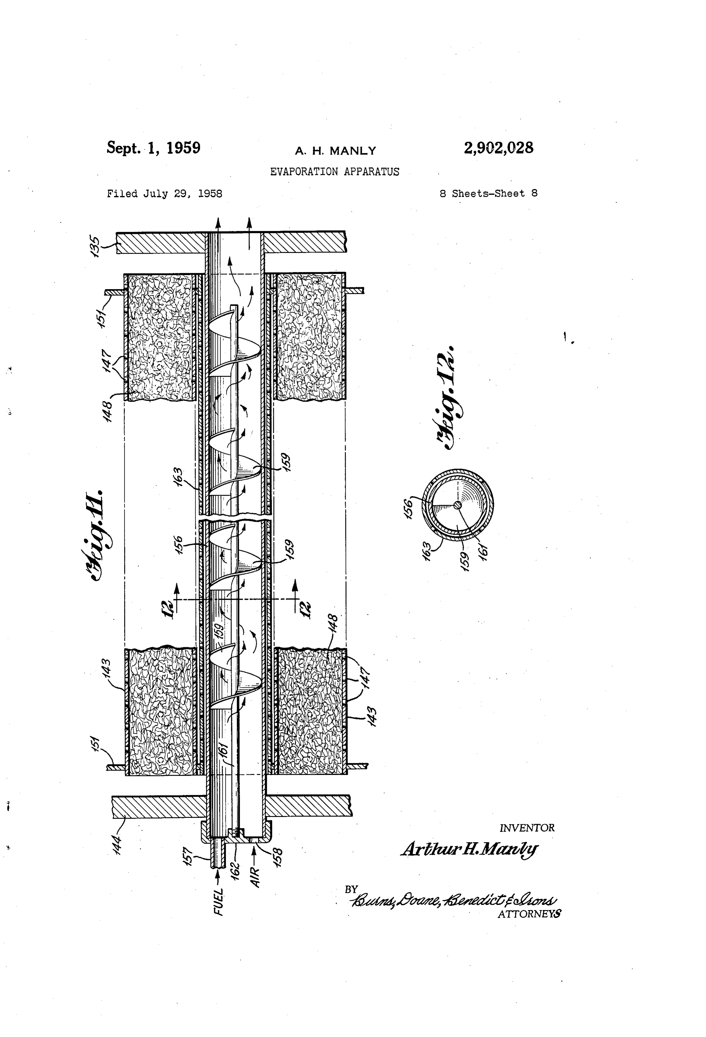
Figure 11 is a vertical section showing a modified form of heating tube; and
Figure 12 is a vertical section taken along the line 2,902,028 12-12 of Figure 11.
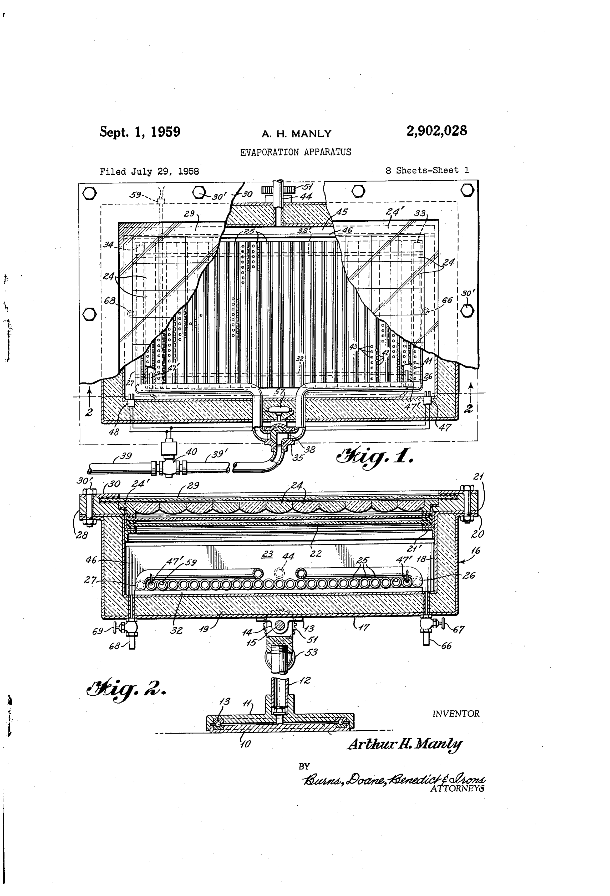
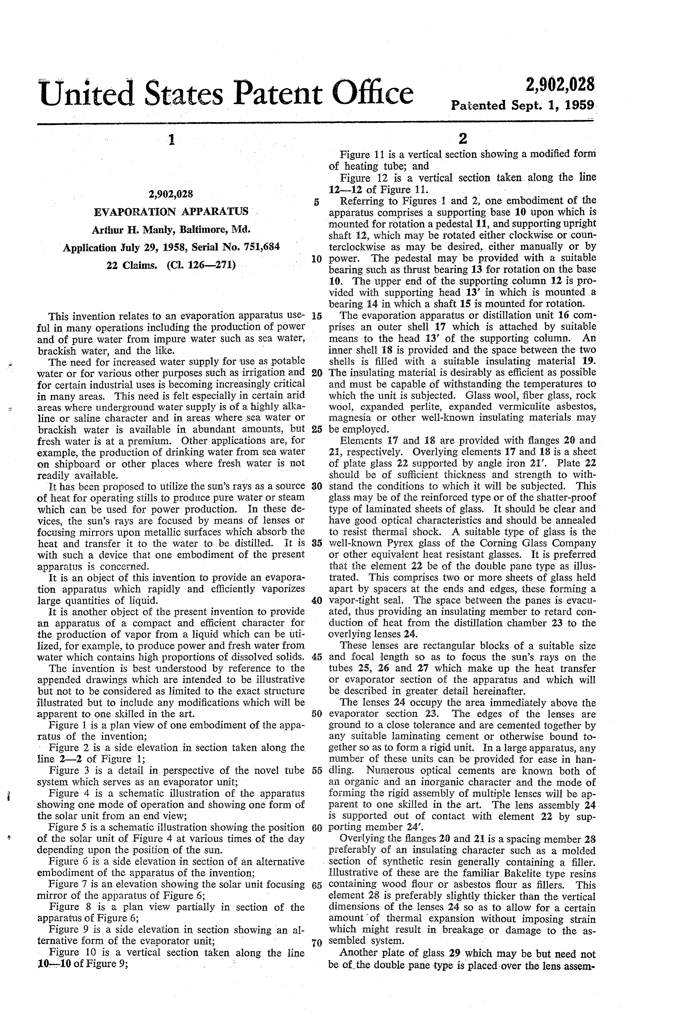
Referring to Figures 1 and 2, one embodiment of the
EVAPORATION APPARATUS . apparatus comprises a supporting base 10 upon which is Arthur H. Manly, Baltimore, Md. mounted for rotation a pedestal 11, and supporting upright shaft A2, which may be rotated either clockwise or coun
Application July 29, 1958, Serial No. 751,684 terclockwise as may be desired, either manually or by O power. The pedestal may be provided with a suitable 22 Claims. (C. 126-271) bearing such as thrust bearing 13 for rotation on the base 10. The upper end of the supporting column 12 is pro vided with supporting head 13 in which is mounted a bearing 4 in which a shaft 15 is mounted for rotation.
This invention relates to an evaporation apparatus use 5 The evaporation apparatus or distillation unit 16 com ful in many operations including the production of power prises an outer shell 17 which is attached by suitable and of pure water from impure water Such as Sea Water, means to the head 13' of the supporting column. An brackish water, and the like. inner shell 18 is provided and the space between the two The need for increased water supply for use as potable shells is filled with a suitable insulating material 19. water or for various other purposes such as irrigation and 20 The insulating material is desirably as efficient as possible for certain industrial uses is becoming increasingly critical and must be capable of withstanding the temperatures to in many areas. This need is felt especially in certain arid which the unit is subjected. Glass wool, fiberglass, rock areas where underground water supply is of a highly alka wool, expanded perlite, expanded vermiculite asbestos, line or saline character and in areas where Sea Water or magnesia or other well-known insulating materials may brackish water is available in abundant amounts, but 25 be employed.
fresh water is at a premium. Other applications are, for Elements 7 and 8 are provided with flanges 20 and example, the production of drinking water from Sea water 23, respectively. Overlying elements 17 and 18 is a sheet on shipboard or other places where fresh water is not of plate glass 22 supported by angle iron 2'. Plate 22 readily available. should be of sufficient thickness and strength to with It has been proposed to utilize the Sun's rays as a source 30 stand the conditions to which it will be subjected. This of heat for operating stills to produce pure Water or Steam glass may be of the reinforced type or of the shatter-proof which can be used for power production. In these de type of laminated sheets of glass. It should be clear and vices, the Sun's rays are focused by means of lenses or have good optical characteristics and should be annealed focusing mirrors upon metallic surfaces which absorb the to resist thermal shock. A suitable type of glass is the heat and transfer it to the water to be distilled. It is 35 well-known Pyrex glass of the Corning Glass Company with such a device that one embodiment of the present or other equivalent heat resistant glasses. It is preferred apparatus is concerned. that the element 22 be of the double pane type as illus It is an object of this invention to provide an evapora trated. This comprises two or more sheets of glass held tion apparatus which rapidly and efficiently vaporizes apart by spacers at the ends and edges, these forming a large quantities of liquid. 40 vapor-tight seal. The space between the panes is evacu It is another object of the present invention to provide ated, thus providing an insulating member to retard con an apparatus of a compact and efficient character for duction of heat from the distillation chamber 23 to the the production of vapor from a liquid which can be uti overlying lenses 24.
lized, for exampie, to produce power and fresh water from These lenses are rectangular blocks of a suitable size water which contains high proportions of dissolved solids. 45 and focal length so as to focus the sun's rays on the The invention is best understood by reference to the tubes 25, 26 and 27 which make up the heat transfer appended drawings which are intended to be illustrative or evaporator Section of the apparatus and which will but not to be considered as limited to the exact structure be described in greater detail hereinafter. illustrated but to include any modifications which will be The lenses 24 occupy the area immediately above the apparent to one skilled in the art. 50 evaporator Section 23. The edges of the lenses are Figure i is a plan view of one embodiment of the appa ground to a close tolerance and are cemented together by ratus of the invention; any Suitable laminating cement or otherwise bound to Figure 2 is a side elevation in section taken along the gether so as to form a rigid unit. In a large apparatus, any line 2-2 of Figure 1; number of these units can be provided for ease in han Figure 3 is a detail in perspective of the novel tube 55 dling. Numerous optical cements are known both of system which serves as an evaporator unit; an organic and an inorganic character and the mode of i Figure 4 is a schematic illustration of the apparatus forming the rigid assembly of multiple lenses will be ap showing one mode of operation and showing one form of parent to one skilled in the art. The lens assembly 24 the solar unit from an end view; is Supported out of contact with element 22 by sup Figure 5 is a schematic illustration showing the position 60 porting member 24'.
of the solar unit of Figure 4 at various times of the day Overlying the flanges 20 and 2 is a spacing member 28 depending upon the position of the sun. preferably of an insulating character such as a molded Figure 6 is a side elevation in section of an alternative Section of synthetic resin generally containing a filler. embodiment of the apparatus of the invention; Illustrative of these are the familiar Bakelite type resins Figure 7 is an elevation showing the solar unit focusing 65 containing wood flour or asbestos flour as fillers. This mirror of the apparatus of Figure 6; element 28 is preferably slightly thicker than the vertical Figure 8 is a plan view partially in section of the dimensions of the lenses 24 so as to allow for a certain apparatus of Figure 6; amount of thermal expansion without imposing strain Figure 9 is a side elevation in section showing an al which might result in breakage or damage to the as ternative form of the evaporator unit; 70 sembled system.
Figure 10 is a vertical section taken along the line Another plate of glass 29 which may be but need not 10-10 of Figure 9; be of the double pane type is placed-over the lens assem
Page 10
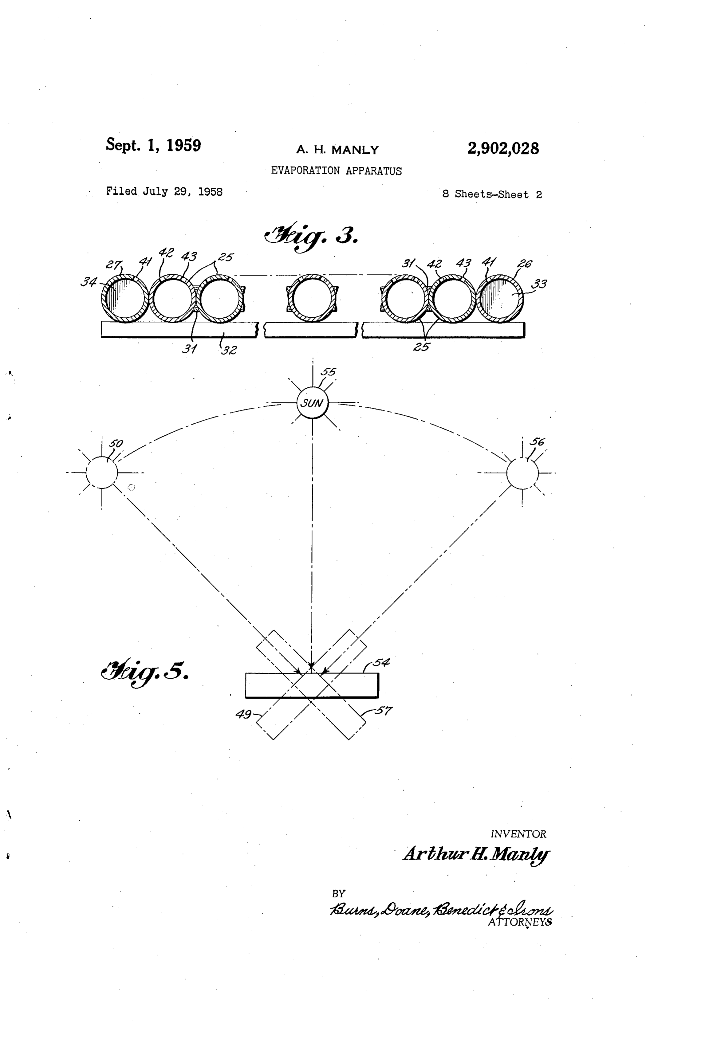
bly and is supported in a recess cut in the element 28. the Sun's rays, for example, as shown schematically at Although this plate 29 could be dispensed with, it is de 49 in Figure 5 when the sun is in the position shown at sirable to use it since it tends to prevent damage to the 50. This angle is adjusted by rotating the shaft 15, for lenses. It can be easily cleaned; and if, after extensive example, by means of the gear and motor assembly 51, cleaning it becomes scratched so as to interfere with the 52 and 53 until the rays of the sun strike the lens as efficiency of the apparatus, it can be readily replaced Sembly at an angle approximately perpendicular thereto. with a new plate. The motor and gear assembly is of a type which will The entire assemblage is held together by any suitable rotate the shaft 15 at a rate corresponding to the move means such as the flange 30 and bolts 30'. Quick-acting ment of the hour hand of a clock so that from the time clamps or other Suitable means could be employed. Suit O the operation is begun in the morning until it is stopped able gasket material preferably resilient and having in in the evening the angle of incidence of the sun's rays Sulating characteristics, may be placed between the vari on the assembly is automatically adjusted throughout the ous matching surfaces in order to provide the necessary day. Any other suitable means for accomplishing this Seal. Usually, the pressure within the evaporator system may be provided. - is not extremely high but may reach in some types of Various positions of the solar unit during the day will operation relatively low superatmospheric pressures such be noted from Figure 5. For example, at noon the unit as up to about 50 pounds per square inch, so the seal will be in a position shown at 54 when the sun is at 55. must be effective. In the afternoon when the sun is at 56, the unit will be The evaporator unit comprises a bank of open-ended in the position shown at 57. Axis 15 is in a generally tubes 25. These tubes are placed side by side and are 20 north and South line in the morning and evening, although silver soldered or otherwise permanently attached in heat this will deviate therefrom due to variations in the earth's exchange relationship to each other as shown at 31 in orbit around the Sun at the different seasons of the year Figure 3. They are attached to metal bars or strips 32 and the geographical location of the plant. of which there may be several, which lends rigidity to In order to compensate for the change in the earth's the assembly. The feed tubes 26 and 27 lie close to, 25 orbit at various seasons and the geographic location of but are not attached to, the adjacent tube as shown in the plant, the unit is rotated around axis 12 by turning Figure 3. This is so that the assembly of open-ended element 11 by any suitable means, not shown, to the tubes forming the evaporator may be lifted from the solar proper position necessary to keep the distillation unit unit for cleaning or repairs without disturbing the feed turned toward the sun. The means for mounting the tubes. The feed tubes 26 and 27 are plugged at one end 30 distillation unit for effecting the pivotal movement around as shown at 33 and 34. Tubes 26 and 27 are connected axis 15 and for rotating the device around axis 12 to to a solenoid-operated plug valve 35 which is provided the proper position to keep the face of the distillation unit with a curved opening 38. The valve is connected to normal to the Sun's rays, forms no part of my inven a water inlet line 39. By proper rotation of the plug, tion, per se, since any suitable means known to those the passageway 38 will supply water to either feed tube skilled in the art may be used. My invention lies in the 26 or feed tube 27 as may be required and as will be distillation or evaporator unit itself.
more fully explained hereinafter. The raw water feed Assuming that the operation begins with the sun shown line 39 is provided with a control valve 40 for regulating as at 50 and the unit in the position at 49 of Figure 5, the rate of water feed, this in turn being attached to a the solenoid valve 35 is set with the opening 38 in the flexible tube 39 leading to the main feed-water supply 40 position as shown. Water which is filtered to remove line. any solid particles that might tend to plug the appara Each of the feed tubes 26 and 27 is provided with a tus passes through line 39, valve 40 and aperture 38 into multiplicity of spaced apertures 41. This row of aper line 26 and is sprayed through the apertures 41. The tures is drilled at an angle of about 30° or any desired water cascades downwardly over the tubes 25 which are angle from top center. The adjacent open-ended tube being heated by the Sun's rays focused on the evaporator is provided with apertures 42 drilled at a corresponding 45 section by the lenses 24. The water sprays out over the angle to apertures 4; and which are preferably in stag tubes and some of it passes into the interior of the tubes gered relationship to the apertures 4A. The tube adja through the apertures 42 and 43. Since the tubes 25 cent to the feed tube is also provided with a series of are of metal Such as copper or any other good heat con apertures 43 drilled at a like angle and preferably stag 50 ductor, including stainless steel and the like, not only the gered in relationship to the apertures 42. Each of the portion of the tubes exposed to the sun's rays, but the other open-ended tubes is provided with apertures 42 interior of the tubes are heated by conduction. Conse and 43 but these are not illustrated for purposes of sim quently, water is evaporated both on the outer surface plification. Opposite the water inlet side of the device as it cascades over the metal and also from the interior or in any other suitable location is a steam outlet line 55 of the tubes 25 from whence steam passes through the or steam hose 44 which may lead to a heat engine such open ends into the upper portion of the distillation zone. as a steam turbine or to suitable coolers and condensers The steam passes over baffle 46 into the manifold space for recovery of the steam condensate as potable water. 45 and out through steam outlet line 44. Outlet line 44 communicates with the space between The rate of flow of water is adjusted so that all of element 18 and the open ends of tubes 25. This space 60 the tubes are wetted with the possible exception of the s 45 serves as a collecting manifold for the water vapors generated in the evaporator. A baffle 46 is provided ad last few of the lower tubes. If the water is not com pletely evaporated before it reaches the end of the unit jacent the ends of tubes 25 and is interposed between adjacent the wet relay 47, it causes the relay to operate the steam outlet line and the ends of the tubes. This which in turn causes motor control valve 40 to close baffle preferably extends approximately two-thirds to 65 somewhat to reduce the rate of feed water. A thermo three-fourths of the height of the distillation section 23. static control 47' is mounted on a tube adjacent the lower It is sealed to the shell 18 both at the ends and bottom end of the tube chest so that when the water supply is and its purpose is to prevent any water and salts from reduced to too low a value the temperature of the tube being swept into the outlet line 44 and thus contaminating will rise and cause the valve to open slightly. Thus, the the steam. At each end of the device adjacent the bottom 70 Supply of feed water will automatically be adjusted to of element 18 are wet relays 47 and 48. These relays the maximum rate for the heat capacity of the unit. It or their equivalent are connected through a suitable cir must be realized that various factors will influence the cuit with the motor controlled valve 40. Their purpose capacity of the unit. These may include the condition will be explained more fully hereinafter. of the atmosphere, the season of the year, etc. An im ... In operation, the distillation unit is set at an angle to 5 portant factor is the accumulation of solids on the tubes
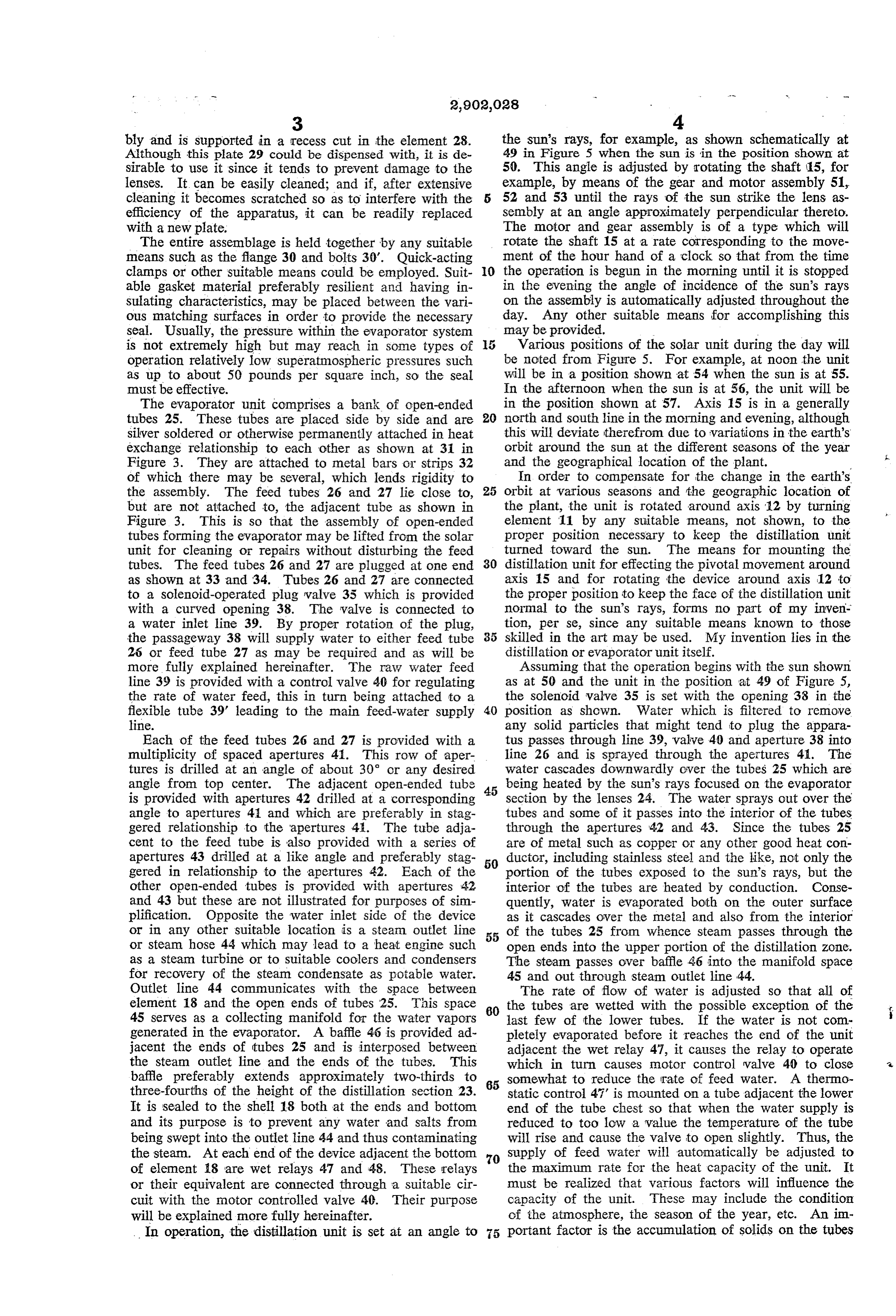
Page 11
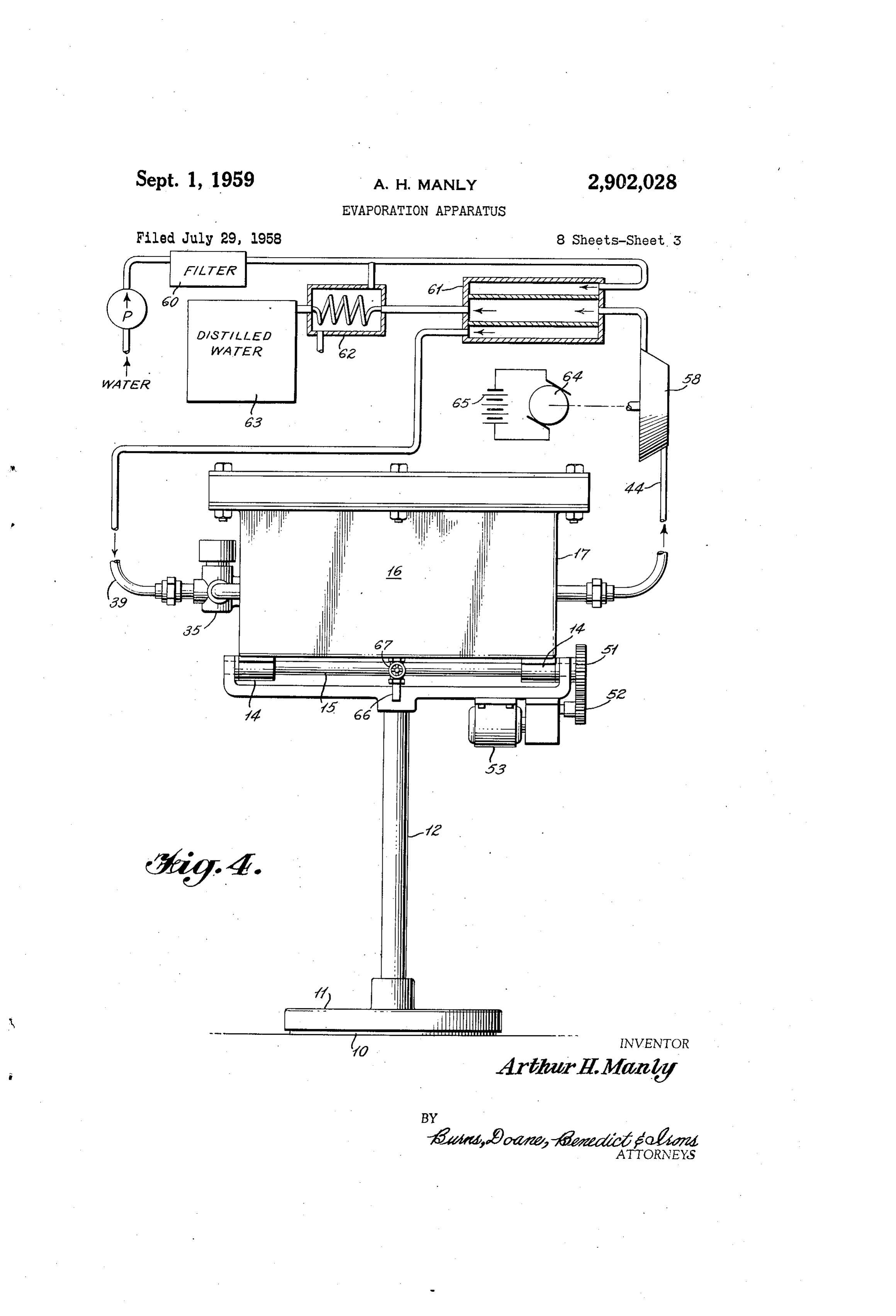
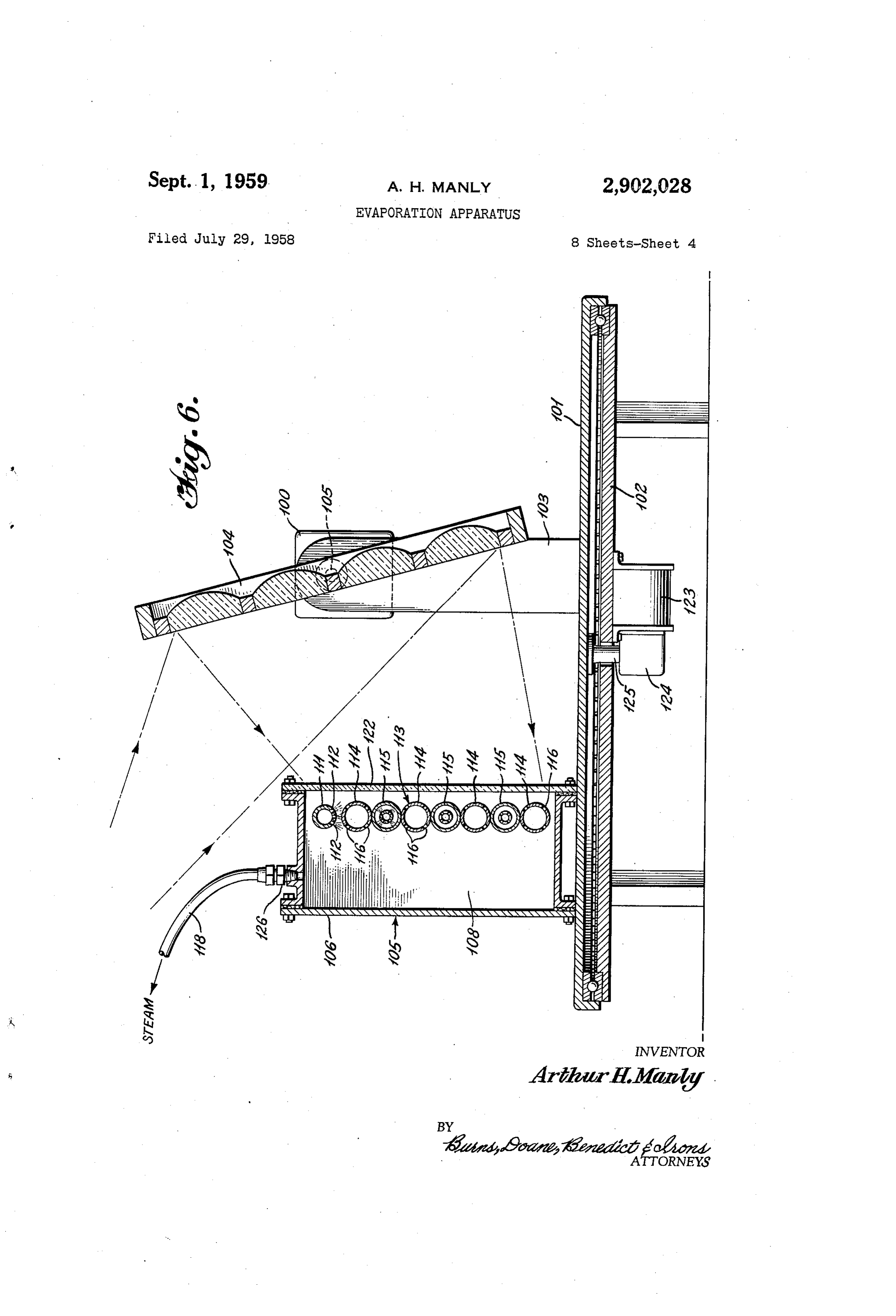
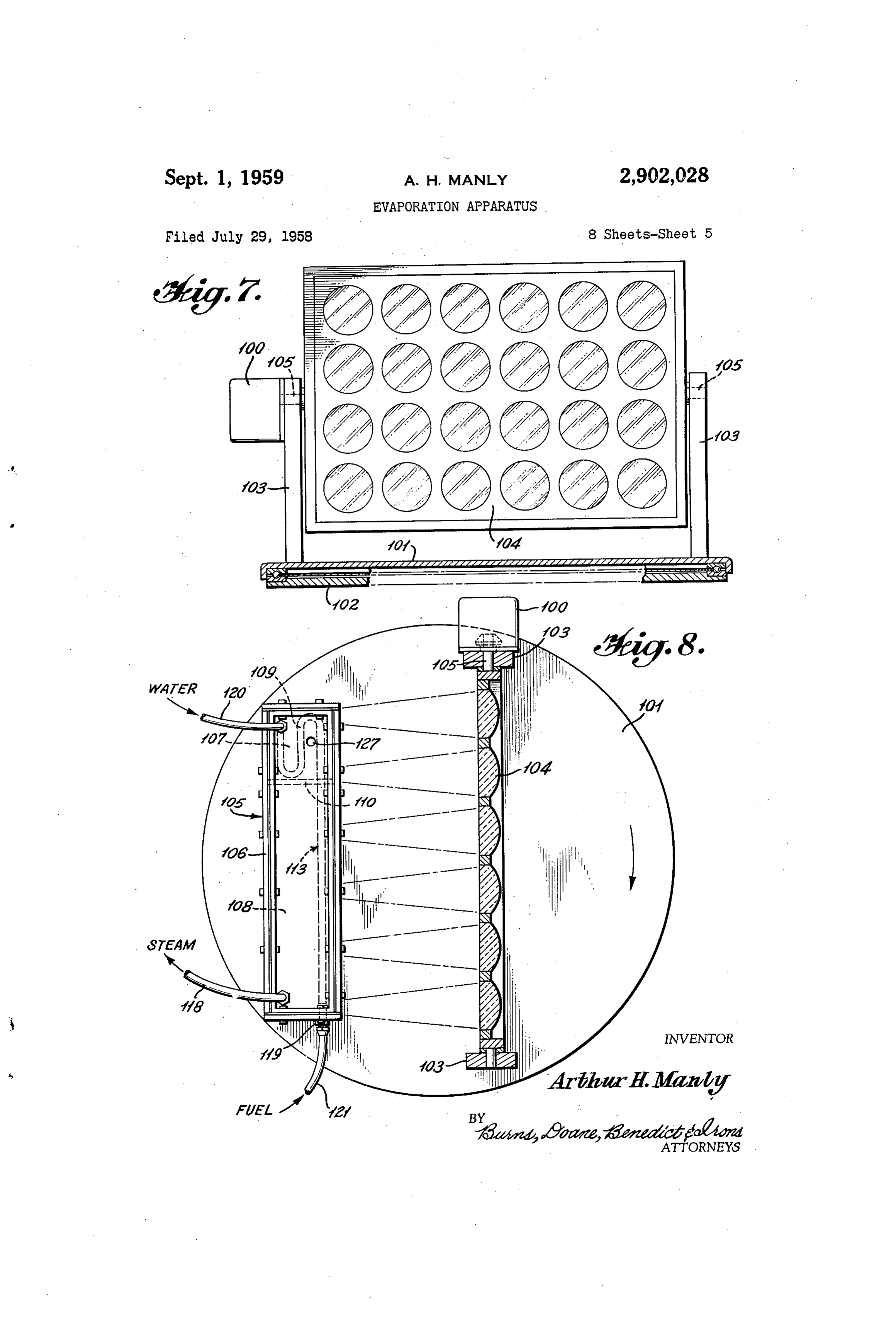
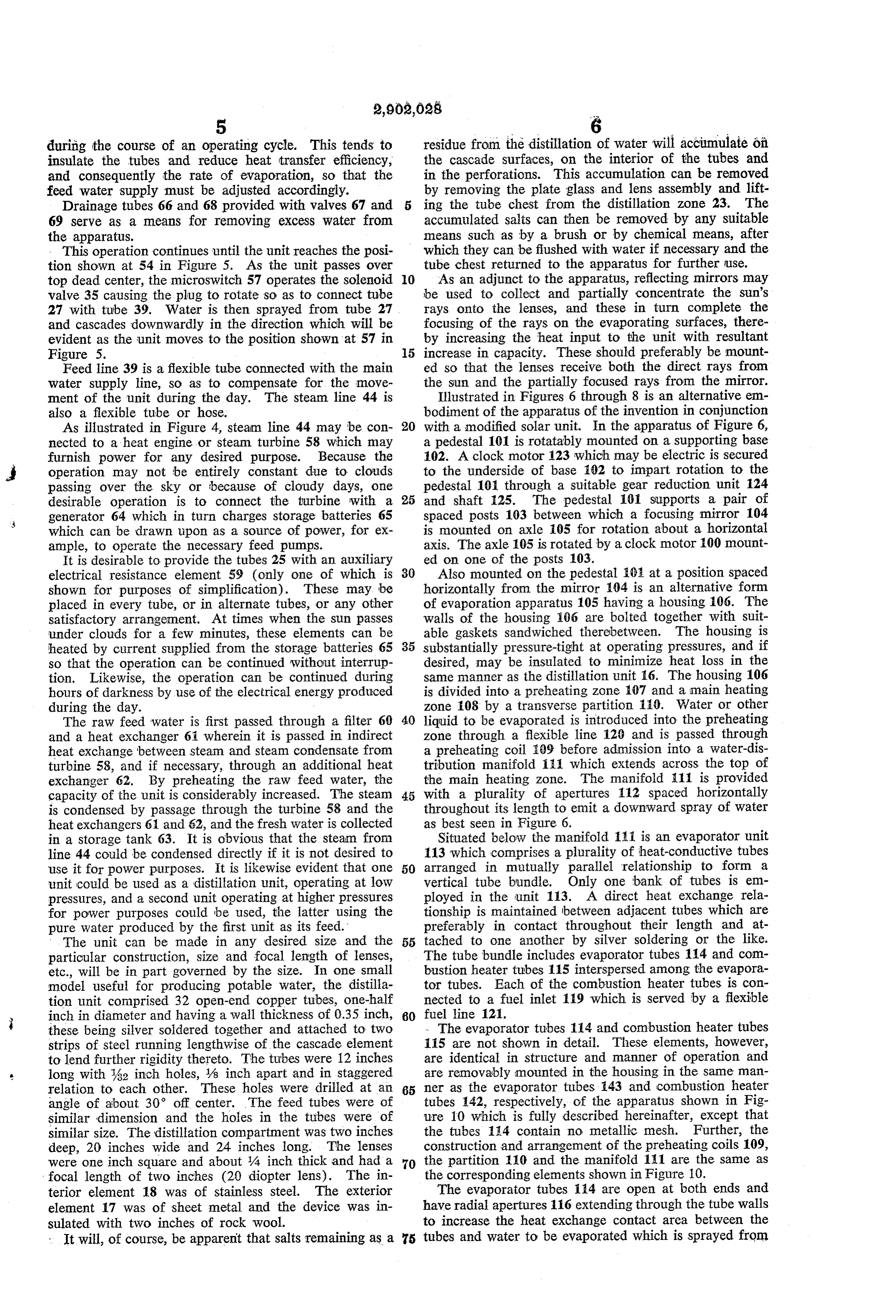
during the course of an operating cycle. This tends to residue from the distillation of water will accumulate of insulate the tubes and reduce heat transfer efficiency, the cascade surfaces, on the interior of the tubes and and consequently the rate of evaporation, so that the in the perforations. This accumulation can be removed feed water supply must be adjusted accordingly. by removing the plate glass and lens assembly and lift Drainage tubes 66 and 68 provided with valves 67 and ing the tube chest from the distillation zone 23. The 69 serve as a means for removing excess water from accumulated salts can then be removed by any suitable the apparatus. means such as by a brush or by chemical means, after This operation continues until the unit reaches the posi which they can be flushed with water if necessary and the tion shown at 54 in Figure 5. As the unit passes over tube chest returned to the apparatus for further use. top dead center, the microswitch 57 operates the solenoid 0. As an adjunct to the apparatus, reflecting mirrors may valve 35 causing the plug to rotate so as to connect tube be used to collect and partially concentrate the Sun's 27 with tube 39. Water is then sprayed from tube 27 rays onto the lenses, and these in turn complete the and cascades downwardly in the direction which will be focusing of the rays on the evaporating surfaces, there evident as the unit moves to the position shown at 57 in by increasing the heat input to the unit with resultant Figure 5. 15 increase in capacity. These should preferably be mount Feed line 39 is a flexible tube connected with the main ed so that the lenses receive both the direct rays from water supply line, so as to compensate for the move the Sun and the partially focused rays from the mirror. ment of the unit during the day. The steam line 44 is Illustrated in Figures 6 through 8 is an alternative em also a flexible tube or hose. bodiment of the apparatus of the invention in conjunction As illustrated in Figure 4, steam line 44 may be con 20 with a modified solar unit. In the apparatus of Figure 6, nected to a heat engine or steam turbine 58 which may a pedestal 101 is rotatably mounted on a supporting base furnish power for any desired purpose. Because the 102. A clock motor 123 which may be electric is secured operation may not be entirely constant due to clouds to the underside of base 102 to impart rotation to the passing over the sky or because of cloudy days, one pedestal 101 through a suitable gear reduction unit 124 desirable operation is to connect the turbine with a 25 and shaft 25. The pedestal 101 Supports a pair of generator 64 which in turn charges storage batteries 65 spaced posts 103 between which a focusing mirror 104 which can be drawn upon as a source of power, for ex is mounted on axle 05 for rotation about a horizontal ample, to operate the necessary feed pumps. axis. The axle 105 is rotated by a clock motor 100 mount It is desirable to provide the tubes 25 with an auxiliary ed on one of the posts 103.
electrical resistance element 59 (only one of which is 30 Also mounted on the pedestal 102 at a position spaced shown for purposes of simplification). These may be horizontally from the mirror 104 is an alternative form placed in every tube, or in alternate tubes, or any other of evaporation apparatus 105 having a housing 106. The satisfactory arrangement. At times when the sun passes walls of the housing 66 are bolted together with suit under clouds for a few minutes, these elements can be able gaskets sandwiched therebetween. The housing is heated by current supplied from the storage batteries 65 35 substantially pressure-tight at operating pressures, and if so that the operation can be continued without interrup desired, may be insulated to minimize heat loss in the tion. Likewise, the operation can be continued during same manner as the distillation unit 16. The housing 106 hours of darkness by use of the electrical energy produced is divided into a preheating zone 107 and a main heating during the day. zone 108 by a transverse partition 110. Water or other The raw feed water is first passed through a filter 60 40 liquid to be evaporated is introduced into the preheating and a heat exchanger 6 wherein it is passed in indirect zone through a flexible line 120 and is passed through heat exchange between steam and steam condensate from a preheating coil 09 before admission into a water-dis turbine 58, and if necessary, through an additional heat tribution manifold i:1 which extends across the top of exchanger 62. By preheating the raw feed water, the the main heating zone. The manifold 111 is provided capacity of the unit is considerably increased. The steam 45 with a plurality of apertures 112 spaced horizontally is condensed by passage through the turbine 58 and the throughout its length to emit a downward spray of Water heat exchangers 61 and 62, and the fresh water is collected as best seen in Figure 6.
in a storage tank 63. It is obvious that the steam from Situated below the manifold Ai is an evaporator unit line 44 could be condensed directly if it is not desired to 113 which comprises a plurality of heat-conductive tubes use it for power purposes. It is likewise evident that one 50 arranged in mutually parallel relationship to form a unit could be used as a distillation unit, operating at low vertical tube bundle. Only one bank of tubes is em pressures, and a second unit operating at higher pressures ployed in the unit 113. A direct heat exchange rela for power purposes could be used, the latter using the tionship is maintained between adjacent tubes which are pure water produced by the first unit as its feed. preferably in contact throughout their length and at The unit can be made in any desired size and the 55 tached to one another by silver soldering or the like. particular construction, size and focal length of lenses, The tube bundle includes evaporator tubes 114 and com etc., will be in part governed by the size. In one small bustion heater tubes 115 interspersed among the evapora model useful for producing potable water, the distilla tor tubes. Each of the combustion heater tubes is con tion unit comprised 32 open-end copper tubes, one-half nected to a fuel inlet 119 which is served by a flexible inch in diameter and having a wall thickness of 0.35 inch, 60 fuel line 121.
these being silver soldered together and attached to two - The evaporator tubes 114 and combustion heater tubes strips of steel running lengthwise of the cascade element 115 are not shown in detail. These elements, however, to lend further rigidity thereto. The tubes were 12 inches are identical in structure and manner of operation and long with 32 inch holes, /8 inch apart and in staggered are removably mounted in the housing in the same man relation to each other. These holes were drilled at an 65 ner as the evaporator tubes 143 and combustion heater angle of about 30° off center. The feed tubes were of tubes 142, respectively, of the apparatus shown in Fig similar dimension and the holes in the tubes were of lure 10 which is fully described hereinafter, except that similar size. The distillation compartment was two inches the tubes 14 contain no metallic mesh. Further, the deep, 20 inches wide and 24 inches long. The lenses construction and arrangement of the preheating coils 109, were one inch square and about 4 inch thick and had a 70 the partition 110 and the manifold 111 are the same as focal length of two inches (20 diopter lens). The in the corresponding elements shown in Figure 10. terior element 18 was of stainless steel. The exterior The evaporator tubes 114 are open at both ends and element 17 was of sheet metal and the device was in have radial apertures 116 extending through the tube walls sulated with two inches of rock wool. to increase the heat exchange contact area between the It will, of course, be apparent that salts remaining as a 75 tubes and water to be evaporated which is sprayed from
Page 12
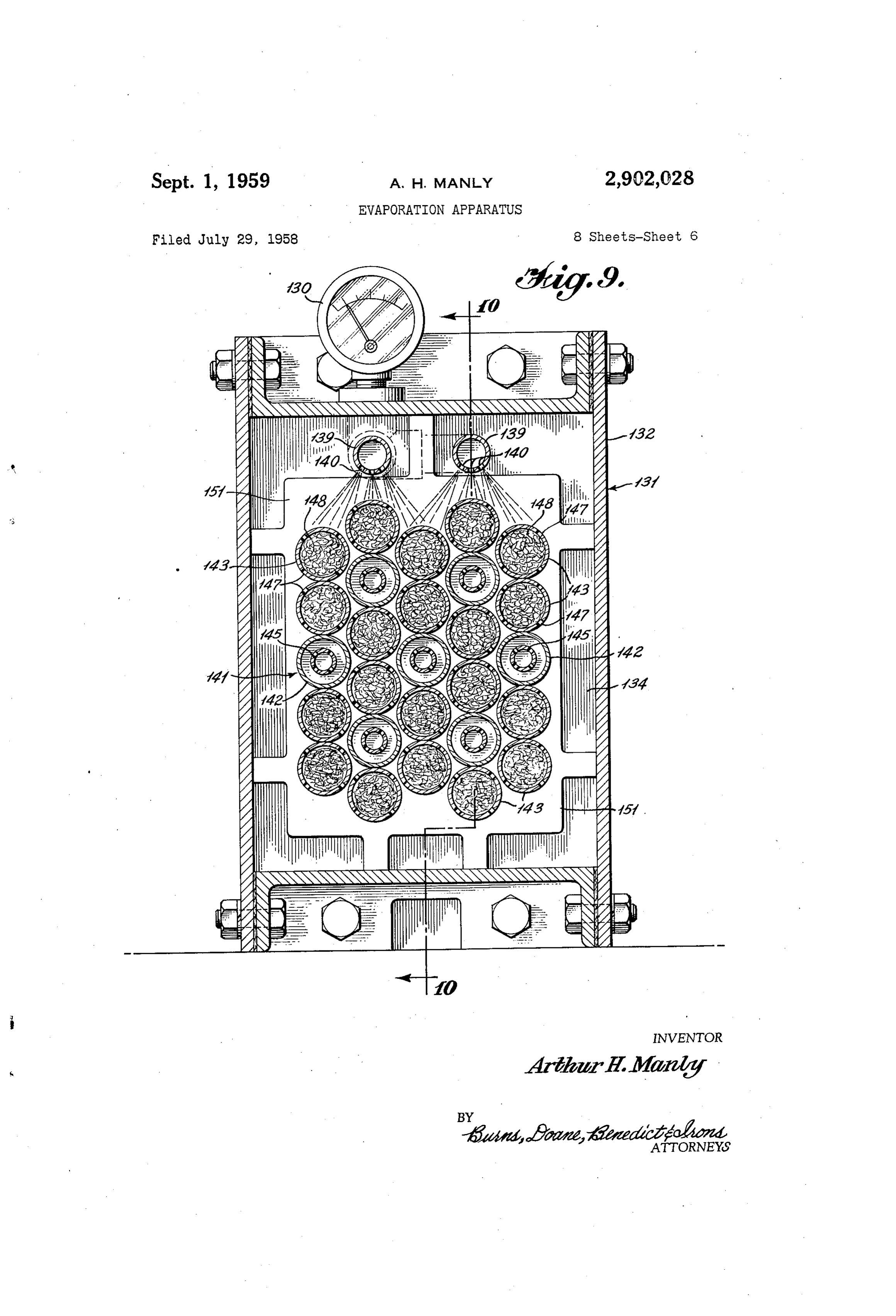
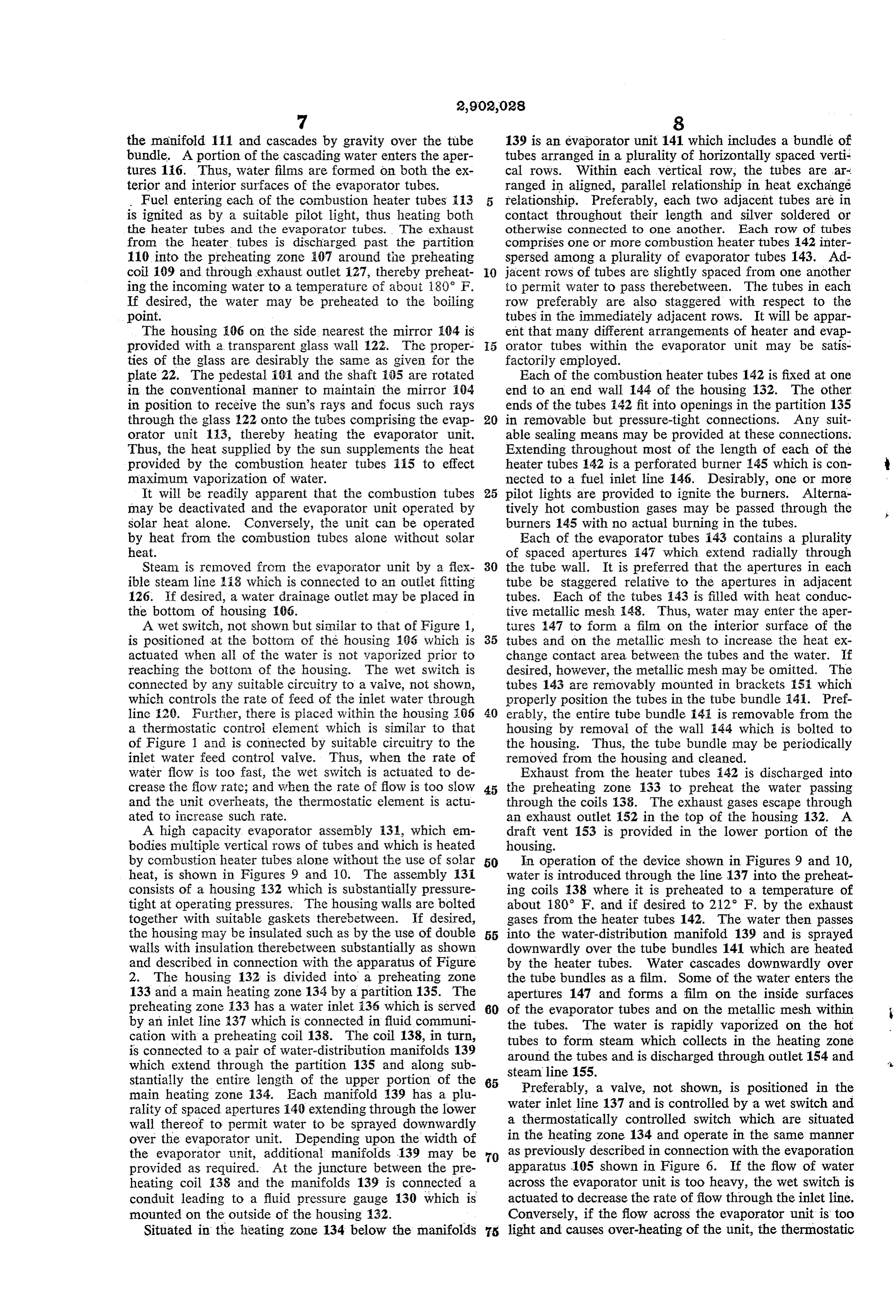
the manifold 111 and cascades by gravity over the tube 139 is an evaporator unit 141 which includes a bundle of bundle. A portion of the cascading water enters the aper tubes arranged in a plurality of horizontally spaced verti tures 16. Thus, water films are formed on both the ex cal rows. Within each vertical row, the tubes are ar. terior and interior surfaces of the evaporator tubes. ranged in aligned, parallel relationship in heat exchange Fuel entering each of the combustion heater tubes 3 relationship. Preferably, each two adjacent tubes are in is ignited as by a suitable pilot light, thus heating both contact throughout their length and silver soldered or the heater tubes and the evaporator tubes. The exhaust otherwise connected to one another. Each row of tubes from the heater tubes is discharged past the partition comprises one or more combustion heater tubes 42 inter 110 into the preheating zone 07 around the preheating spersed among a plurality of evaporator tubes 143. Ad coil 109 and through exhaust outlet 27, thereby preheat O jacent rows of tubes are slightly spaced from one another ing the incoming water to a temperature of about 180° F. to permit water to pass therebetween. The tubes in each If desired, the water may be preheated to the boiling row preferably are also staggered with respect to the point. tubes in the immediately adjacent rows. It will be appar The housing E06 on the side nearest the mirror 04 is ent that many different arrangements of heater and evap provided with a transparent glass wall 22. The proper 5 orator tubes within the evaporator unit may be satis ties of the glass are desirably the same as given for the factorily employed.
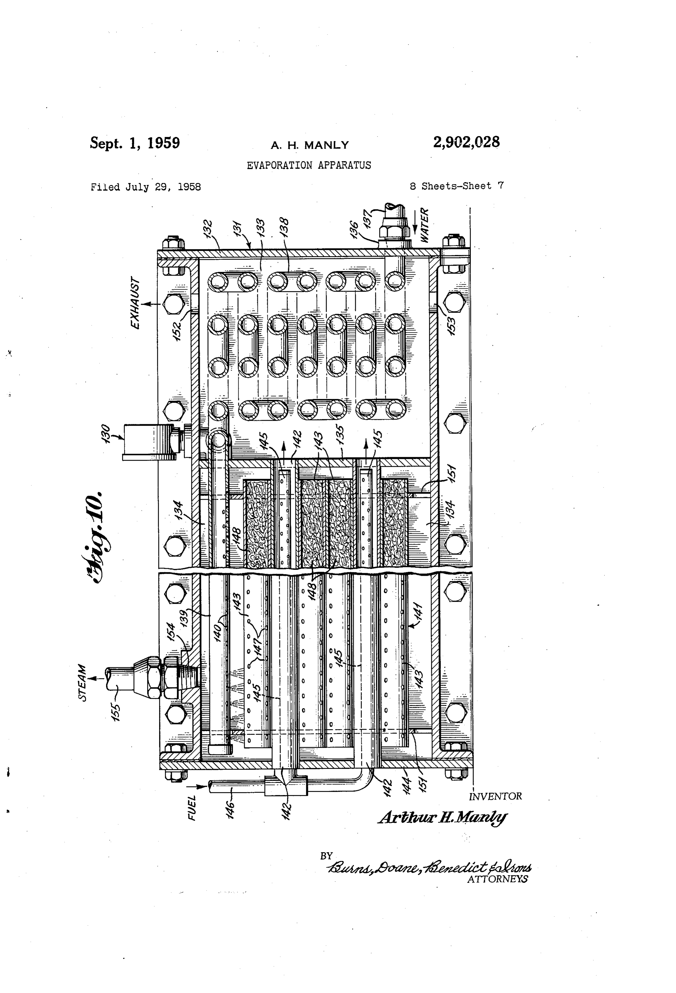
piate 22. The pedestal 91 and the shaft 05 are rotated Each of the combustion heater tubes 142 is fixed at one in the conventional manner to maintain the mirror 04 end to an end wall 44 of the housing 132. The other in position to receive the sun's rays and focus such rays ends of the tubes 42 fit into openings in the partition 135 through the glass 22 onto the tubes comprising the evap 20 in removable but pressure-tight connections. Any suit orator unit 13, thereby heating the evaporator unit. able sealing means may be provided at these connections. Thus, the heat Supplied by the Sun supplements the heat Extending throughout most of the length of each of the provided by the combustion heater tubes ii.5 to effect heater tubes 142 is a perforated burner 145 which is con maximum vaporization of water. nected to a fuel inlet line 146. Desirably, one or more It will be readily apparent that the combustion tubes 25 pilot lights are provided to ignite the burners. Alterna may be deactivated and the evaporator unit operated by tively hot combustion gases may be passed through the solar heat alone. Conversely, the unit can be operated burners 145 with no actual burning in the tubes. by heat from the combustion tubes alone without solar Each of the evaporator tubes 43 contains a plurality heat. of spaced apertures 47 which extend radially through Steam is removed from the evaporator unit by a flex 30 the tube wall. It is preferred that the apertures in each ible steam line i3 which is connected to an outlet fitting tube be staggered relative to the apertures in adjacent 126. If desired, a water drainage outlet may be placed in tubes. Each of the tubes 43 is filled with heat conduc the bottom of housing 106. tive metallic mesh (48. Thus, water may enter the aper A wet switch, not shown but similar to that of Figure 1, tures 147 to form a film on the interior surface of the is positioned at the bottom of the housing 166 which is 35 tubes and on the metallic mesh to increase the heat ex actuated when all of the water is not vaporized prior to change contact area between the tubes and the Water. If reaching the bottom of the housing. The wet switch is desired, however, the metallic mesh may be omitted. The connected by any suitable circuitry to a valve, not shown, tubes 143 are removably mounted in brackets 152 which which controls the rate of feed of the inlet water through properly position the tubes in the tube bundle 141. Pref line 29. Further, there is piaced within the housing iG6 40 erably, the entire tube bundle 14 is removable from the a thermostatic controi element which is similar to that housing by removal of the wall 44 which is bolted to of Figure 1 and is connected by suitable circuitry to the the housing. Thus, the tube bundle may be periodically inlet water feed control valve. Thus, when the rate of removed from the housing and cleaned. water flow is too fast, the wet switch is actuated to de Exhaust from the heater tubes i42 is discharged into crease the flow rate; and when the rate of flow is too slow 45 the preheating Zone 33 to preheat the water passing and the unit overheats, the thermostatic element is actu through the coils i38. The exhaust gases escape through ated to increase Such rate. an exhaust outlet 152 in the top of the housing 132. A A high capacity, evaporator assembly 31, which em draft vent 153 is provided in the lower portion of the bodies multiple vertical rows of tubes and which is heated housing.
by combustion heater tubes alone without the use of solar 50 In operation of the device shown in Figures 9 and 10, heat, is shown in Figures 9 and 10. The assembly 31 water is introduced through the line 137 into the preheat consists of a housing 132 which is substantially pressure ing coils 138 where it is preheated to a temperature of tight at operating pressures. The housing walls are bolted about 180° F. and if desired to 212 F. by the exhaust together with suitable gaskets therebetween. If desired, gases from the heater tubes 142. The water then passes the housing may be insulated such as by the use of double 55 into the water-distribution manifold 139 and is sprayed walls with insulation therebetween substantially as shown downwardly over the tube bundles 141 which are heated and described in connection with the apparatus of Figure by the heater tubes. Water cascades downwardly over 2. The housing 132 is divided into a preheating Zone the tube bundles as a film. Some of the water enters the 133 and a main heating zone 134 by a partition 135. The apertures 147 and forms a film on the inside surfaces preheating zone 133 has a water inlet 36 which is served 60 of the evaporator tubes and on the metallic mesh within by an inlet line 37 which is connected in fluid communi the tubes. The water is rapidly vaporized on the hot cation with a preheating coil 138. The coil 138, in turn, tubes to form steam which collects in the heating Zone is connected to a pair of water-distribution manifolds 139 around the tubes and is discharged through outlet 154 and which extend through the partition 135 and along Sub stantially the entire length of the upper portion of the 65 steam line 155.
Preferably, a valve, not shown, is positioned in the main heating zone 134. Each manifold 139 has a plu water inlet line 137 and is controlled by a wet switch and rality of spaced apertures i40 extending through the lower wall thereof to permit water to be sprayed downwardly a thermostatically controlled switch which are situated over the evaporator unit. Depending upon the width of in the heating zone 134 and operate in the same manner the evaporator unit, additional manifolds 139 may be 70 as previously described in connection with the evaporation provided as required. At the juncture between the pre apparatus 105 shown in Figure 6. If the flow of water heating coil 138 and the manifolds 139 is connected a across the evaporator unit is too heavy, the wet switch is conduit leading to a fluid pressure gauge 130 which is actuated to decrease the rate of flow through the inlet line. mounted on the outside of the housing 132. Conversely, if the flow across the evaporator unit is too Situated in the heating zone 134 below the manifolds s light and causes over-heating of the unit, the thermostatic
Page 13
switch is actuated to increase the rate of flow through the operable to supply feed water to the uppermost of said inlet line. feed lines when the unit is tilted at an angle, means for Depicted in Figures 11 and 12 is an alternative form switching said valve to supply the water to the other of of combustion heater tube, which may be utilized said feed lines when the angle of tilt is reversed, said with either the apparatus shown in Figure 6 or that shown evaporator unit comprising a plurality of open-ended in Figure 9. The burner tube 156 consists of a non tubes lying transverse the normal flow of Water, adjacent apertured tube which is mounted between the exterior tubes being in close proximity, means for maintaining wall 144 and interior partition 135 of the housing 132 said tubes in close proximity to form a rigid removable in the same manner as the tubes 142. The tube 156 has structure, said open-ended tubes being provided with a fuel inlet 157 and an air inlet 158. The fuel and air O apertures to permit a limited flow of the water cascading mixture may be ignited within the tube by a pilot light over said tubes into the interior thereof, a vapor outlet or other means, not shown. The hot combustion from the heating zone and means positioned between said gases pass longitudinally through the tube 156 past heating zone and said vapor outlet for preventing flow of helical baffles 159 which are mounted on a rod 161 which, feed water from said heating zone into said vapor outlet. 2. A solar distillation unit comprising a recessed ex in turn, is connected to the end cap 162 of the tube and 5 teriorly extends axially through the tube. The function of the sealing said insulated shell, a transparent cover, means for baffles 159 is to decrease the rate of flow of the gases cover to said shell in pressure-tight relation ship to form a heating zone, a water inlet and a vapor through the tube and create turbulence, thus more effec outlet, tively utilizing the heat of the combustion gases. An a removable evaporator unit positioned in said evaporator tube 163 is mounted outside of the heater 20 heating zone, means for focusing the Sun's rays on the tube 156 in concentric relationship thereto. When Water surface of said evaporator unit, said evaporator unit in cascades down the tube bundle, it is vaporized by contact cluding a tube bundle comprising a plurality of aligned with the surfaces of the evaporator tubes 143 in the man perforated open-ended tubes, a water distributing mani ner previously described. The provision of an apertured 25 fold adjacent one end of the heating Zone, said manifold evaporator tube around the combustion heater tube fur and said tubes being arranged so that water, when intro ther increases the heat exchange area on which Water duced, will cascade over said tubes from one end of the may be vaporized. unit to the other, said tubes lying transverse the path of A film of water is formed on the exterior surface of the flow of the water.
tube 163 and some water passes through the apertures in 3. The apparatus of claim 2 wherein adjacent open the tube 163 to form films on both the interior surface of 30 ended tubes are sealed together. the tube 163 and the exterior surface of the combustion 4. The apparatus of claim 2 wherein the open-ended tube 156. When combustion tube 156 is substituted for tubes comprise a plurality of apertures throughout the the combustion tubes 142 in the apparatus of Figure 10 length thereof and being located between the top center or of Figure 6, the capacity of the evaporator unit is ma of the tube and the point of contact with an adjacent terially increased. It will be understood that the heater 35 tube.
tube 156 may be employed without the surrounding evap 5. The apparatus of claim 2 wherein each tube com orator tube 163. prises two rows of apertures, one on each side of the top Either of the devices 105 (Figure 6) or 131 (Figure 9) center of the tube.
may be substituted for the device 16 in the power and 40 of 6.apertures
The apparatus of claim 5 wherein alternating rows in said tubes are in staggered relation to each distillation circuit shown in Figure 4.
In any of the forms of apparatus described herein other.
7. The apparatus of claim 2 wherein the means for before, it is evident that the number, size and length of focusing tubes will vary with the size of the equipment. It is also the sun's rays comprises a plurality of lenses evident that the water may be sprayed onto the tubes at mounted above the transparent sealing means, said lenses points intermediate the end of the evaporator unit by Sup 45 having a focal length to produce a substantially maxi mum focus of the Sun's rays on said open-ended tubes plying additional feed tubes. This would be particularly throughout true in the case of large units several feet long. their length.
The metal parts which will come in contact with the 8. The apparatus of claim 7 comprising means for reg hot feed water should be of a corrosion resistant material. ulating the flow of water over said tubes whereby sub The tube chest is preferably made of copper or some 50 stantially all of said tubes are covered with a film of water during operation.
other heat resistant material having high heat conduc 9. The apparatus of claim 2 wherein a portion of the tivity. Glass tubes could be used but are less desirable tubes because the heat conducting characteristics of glass are is equipped with auxiliary heating means. somewhat inferior to metal. 10. In a solar distillation apparatus comprising a solar There has been illustrated and described certain pre 55 evaporator mounted to follow the course of the sun dur ferred embodiments of the apparatus according to the ing the day, the improvement comprising a solar distilla present invention. It is apparent, however, that modifica tion unit comprising a recessed exteriorly insulated shell, tions may be made by those skilled in the art without de a transparent cover, means for sealing said cover to said parting from the scope of the invention as embraced by shell in pressure-tight relationship to form a heating zone, the appended claims. 60 a Water inlet and a vapor outlet, a removable evaporator This is a continuation-in-part of my co-pending appli unit positioned in Said heating zone, means for focusing cation, Serial Number 527,857, filed August 11, 1955, the Sun's rays on the surface of said evaporator unit, said entitled "Solar Still and Power Plant.” evaporator unit including a tube bundle comprising a I claim: plurality of aligned perforated open-ended tubes, a water 1. A solar distillation unit comprising a recessed ex 65 distributing manifold adjacent one end of the heating teriorly insulated shell, transparent means sealing said Zone, said manifold and said tubes being arranged so that recess to form a heating Zone, a removable evaporator Water, when introduced, will cascade over said tubes from unit positioned in said heating zone, means positioned one end of the tube bundle to the other, said tubes lying above the heating zone for focusing the sun's rays on the transverse the path of flow of the water. surface of said evaporator unit, feed water inlet lines in 70 11. A distillation unit for use in a solar distillation fluid communication with said heating zone located ad apparatus which comprises an exterior shell, an interior jacent each end of said evaporator unit and including matching shell in spaced relationship thereto, insulating means for spraying feed water over the surface of said material within the space therebetween, a lens system de evaporator unit, means to tiltably mount said unit to tachably mounted over said interior shell in vapor-tight respectively raise and lower the ends thereof, valve means 75 relationship thereto, a water inlet line located adjacent
Page 14
one end of the interior shell and in fluid communication 18. An evaporation apparatus comprising a substan therewith, said line being connected to a valve and being tially pressure-tight housing providing a heating zone provided wtih a plurality of apertures for producing a therewithin, a liquid distributing manifold positioned in spray of water, said apertures being in a line parallel to said housing, an evaporator unit positioned in said heat the end of the inner shell and set at an angle directed up ing zone and including a bundle of substantially parallel wardly and toward the opposite end of said shell, a re tubes, said tubes being positioned relative to said mani movable bundle of heat-conductive tubes lying in close fold so that liquid when introduced through said mani proximity to each other, said bundle and said inlet line fold will cascade over said tubes, said tubes lying trans being arranged so that water from said inlet line will verse the flow of liquid, said tube bundle including com cascade from one end of the bundle to the other, said O bustion heater and evaporator tubes arranged in close bundle comprising open-ended tubes provided with rows heat exchange relationship, each evaporator tube being of small apertures transverse the flow of water to permit heat conductive and having a perforated wall to permit a portion of the water to enter the interior of the tubes, a portion of the liquid to enter the interior thereof, and and means for removing steam from said unit. means for removing vapor from said housing. 12. An evaporation apparatus comprising a substan 5 19. The apparatus of claim 18 wherein said tubes are tially pressure-tight housing providing a heating Zone arranged in a plurality of slightly spaced vertical rows. therewithin, a manifold positioned in said housing to dis 20. The apparatus of claim 18 further characterized tribute liquid into said heating zone, said housing having by means for focusing the sun's rays on the surface of a vapor outlet, an evaporation unit positioned in said said evaporator unit, at least a portion of one wall of heating zone and including a tube bundle comprising a 20 said housing being transparent to admit the sun's rays. plurality of perforated heat-conductive evaporator tubes, 21. An evaporator unit for use with means to heat means to heat said evaporator unit, said manifold and said unit, and means to supply liquid to said unit which said tubes being arranged so that liquid when introduced comprises a plurality of heat conductive tubes arranged through said manifold will cascade over said tubes to be in a bundle over which liquid may be cascaded, each two vaporized, some of the liquid passing over the exterior adjacent tubes being in direct heat exchange relationship surfaces of the tubes and some of the liquid passing with each other throughout a substantial portion of through the perforations in the tubes onto the interior their length to facilitate heating of the tube bundle, at surfaces thereof, said tubes lying transverse the flow of least a portion of the tube bundle having perforated liquid. . walls to permit a portion of the liquid to enter the inte 13. The apparatus of claim 12 wherein said heating 30 rior thereofthereby increasing the surface contact between means includes at least one combustion heater tube mounted in heat exchange relationship with said evapo said tubes and the liquid.
22. An evaporation apparatus which comprises an rator tubes. evaporator unit, means to supply liquid to said evaporator 14. The apparatus of claim 12 wherein said heating unit and means to heat said evaporator unit, said evapo means comprises in combination means for focusing the 35 rator unit comprising a plurality of heat conductive tubes sun's rays on the surface of said evaporator unit, at least arranged in a bundle over which liquid may be cascaded, a portion of one wall of said housing being transparent each two adjacent tubes being in direct heat exchange to admit the sun's rays, and auxiliary heating means posi relationship with each other throughout a substantial por tioned in said evaporator unit.
15. The apparatus of claim 14 wherein said auxiliary 40 tion of their length to facilitate heating of the tube bundle, at least a portion of the tube bundle having perforated heating means comprises at least one combustion heater walls to permit a portion of the liquid to enter the interior. tube mounted in heat exchange relationship with said evaporator tubes. thereof thereby increasing the surface contact between 16. The apparatus of claim 15 wherein each combus said tubes and the liquid.
tion heater tube is positioned inside one of said evaporator 45 No references cited. tubes.
17. The apparatus of claim 16 wherein each combus tion heater tube contains baffle means mounted therein.
Provenance
- Collection
- Cited prior art
- Original PDF
- patentimages.storage.googleapis.com →
- Filed
- 1958-07-29
- Pages
- 14
- Method
- pdftotext (the PDF's own text layer) + pdftoppm 300dpi page scans
- Source
- Google Patents bibliographic record
- Granted
- 1959-09-01
- Inventors
- Arthur H Manly
- Transcribed from
- patentimages.storage.googleapis.com →