patent · US3915147
Solar energy steam generator
28 October 1975
Page 1 — bibliographic record
United States Patent 19 11 3,915,147 Rineer (45) Oct. 28, 1975 54 SOLAR ENERGY STEAM GENERATOR Primary Examiner-William F. O'Dea 76 Inventor: Arthur E. Rineer, P.O. Box 115, Assistant Examiner-Peter D. Ferguson Beulah, Mich. 496.17 Attorney, Agent, or Firm-Glenn B. Morse, Esq.
Heat-absorption units are mounted at the focus of re flectors, with this relationship being altered in re (52) U.S. Cl. ................................................ 126/271 sponse to conditions in the units and in an insulated (51) Int. Cl.’............................................. F24J 3/02 tank communicating with the units. In one form of the 58 Field of Search............................. 126/270, 271 invention, the units purge themselves of liquid into the tank on development of temperature in the units in ex (56) References Cited cess of the boiling point of liquid in the tank. Further UNITED STATES PATENTS elevation of the temperature defocuses the reflectors, 1989,999 2/1935 Niederle ............................. 126/27 and thus cools the units below the condensation point. 2,030,350 2/1936 Bremser..... ... 126/271 UX In another form of the invention, the units communi 2,133,649 10/1938 Abbot................................. 126/271 cate with the tank at vertically spaced points, and in 2,688,922 9/1954 Bonaventura..... ... 126/270 UX clude a check valve or shut-off valve operable in re 3,105,486 10/1963 Glenn ................................. 126/270 sponse to a temperature in the units below a selected 3,162,189 12/1964 Small et al..... ... 126/270 amount.
3,390,672 7/1968 Snelling.............................. 126/271 7 Claims, 7 Drawing Figures
Page 2
Drawing sheet — no readable text.
Page 3
Drawing sheet — no readable text.
Page 4
Drawing sheet — no readable text.
Page 5
SOLAR ENERGY STEAM GENERATOR
DESCRIPTION OF THE DRAWINGS
BACKGROUND OF THE INVENTION
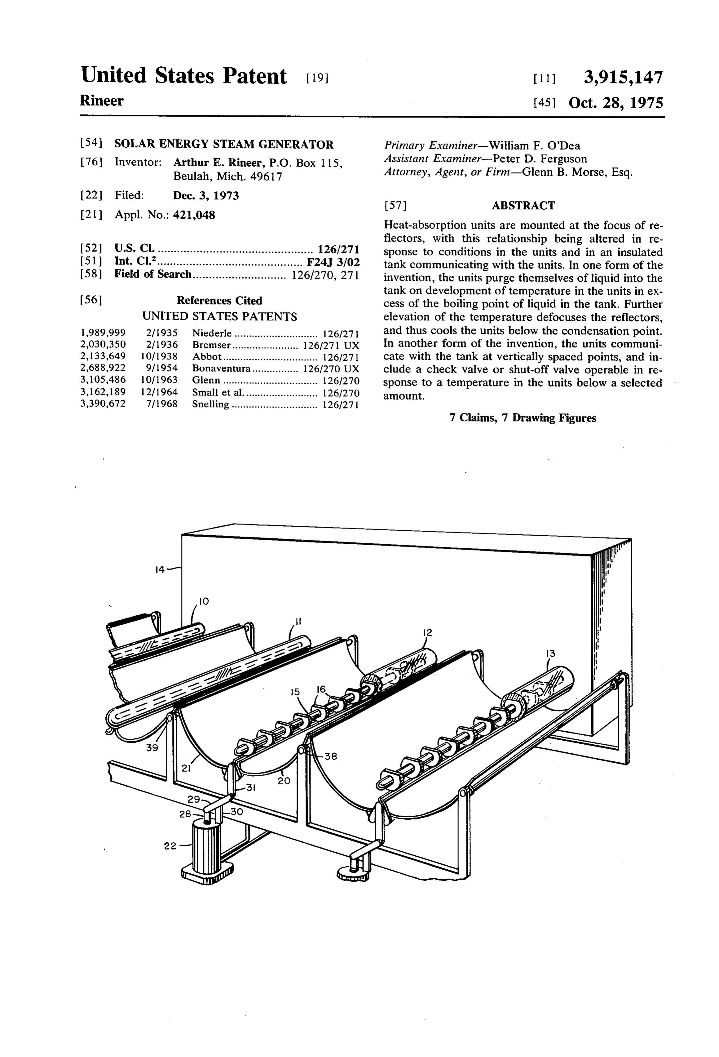
FIG. 1 is a schematic perspective view showing the
Solar heating systems have long been recognized as components of the heat-absorption system of the inven an inviting source of energy. The oldest line of develop tion.
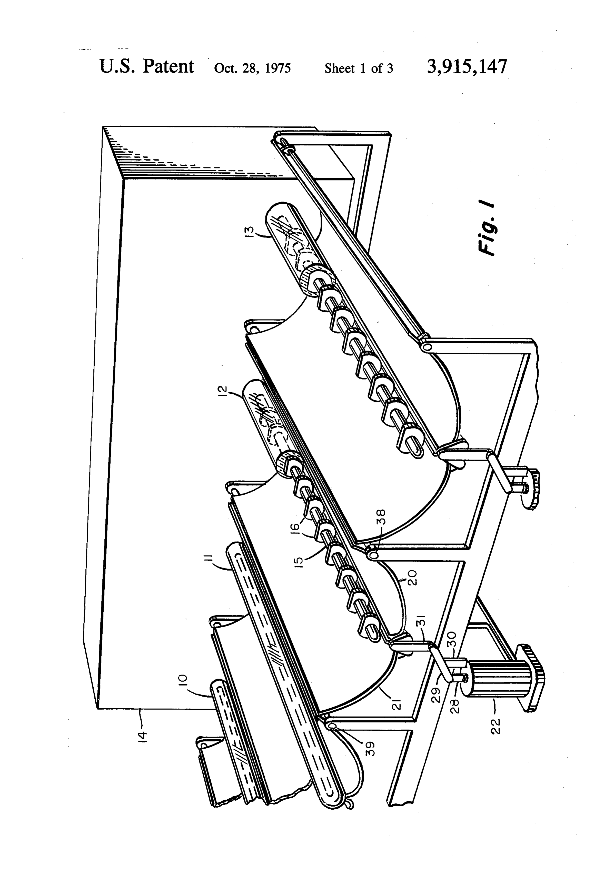
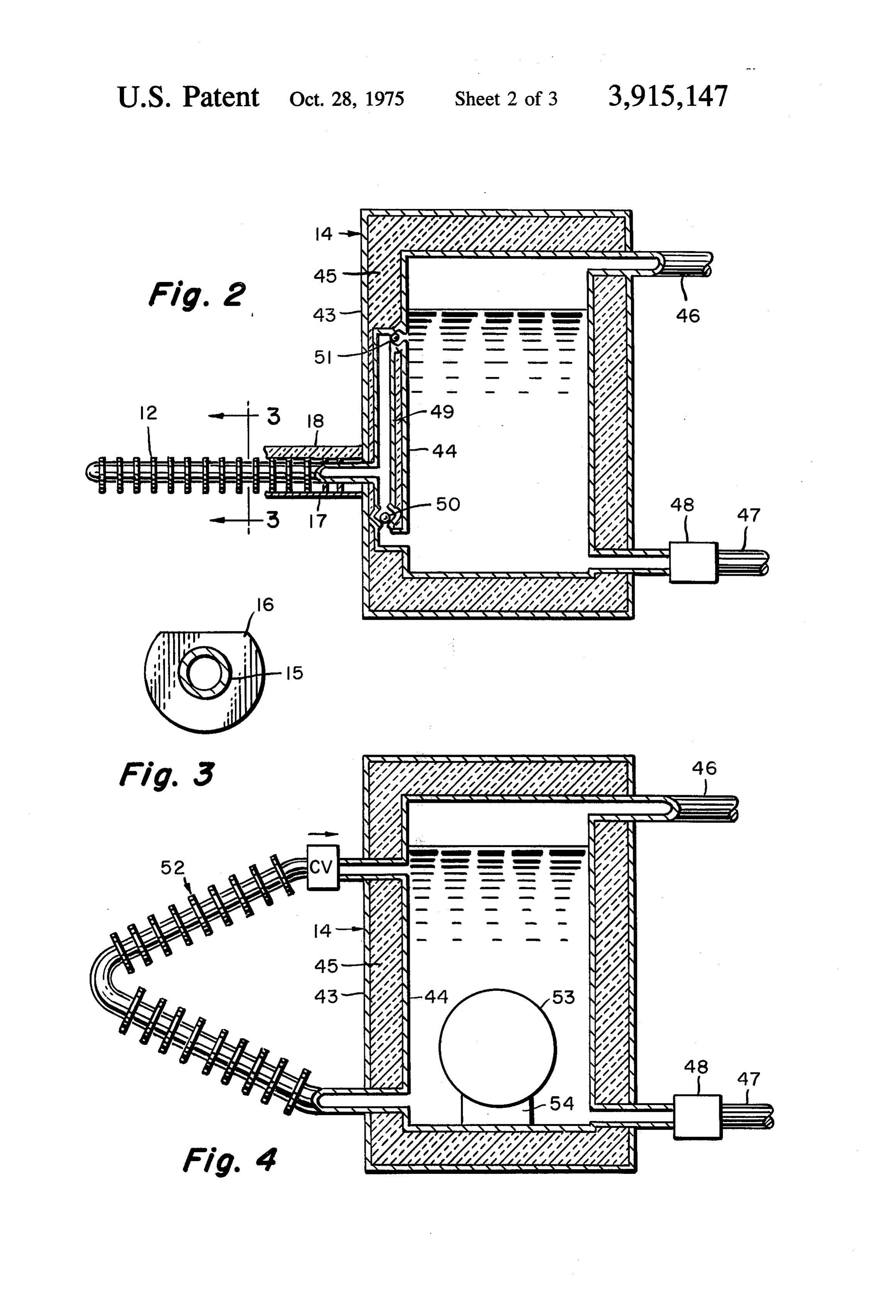
ment of these devices centers in a system which in FIG. 2 is a sectional elevation through an insulated cludes a tank of liquid, tubes communicating with the tank associated with the heat-absorption system illus tank, and reflectors arranged to focus the sun's rays on trated in FIG. 1.
these tubes so that they will function in a similar man FIG. 3 is a section on an enlarged scale on the plane ner to the tubes associated with a boiler. To be at all 10 3-3 of FIG. 2.
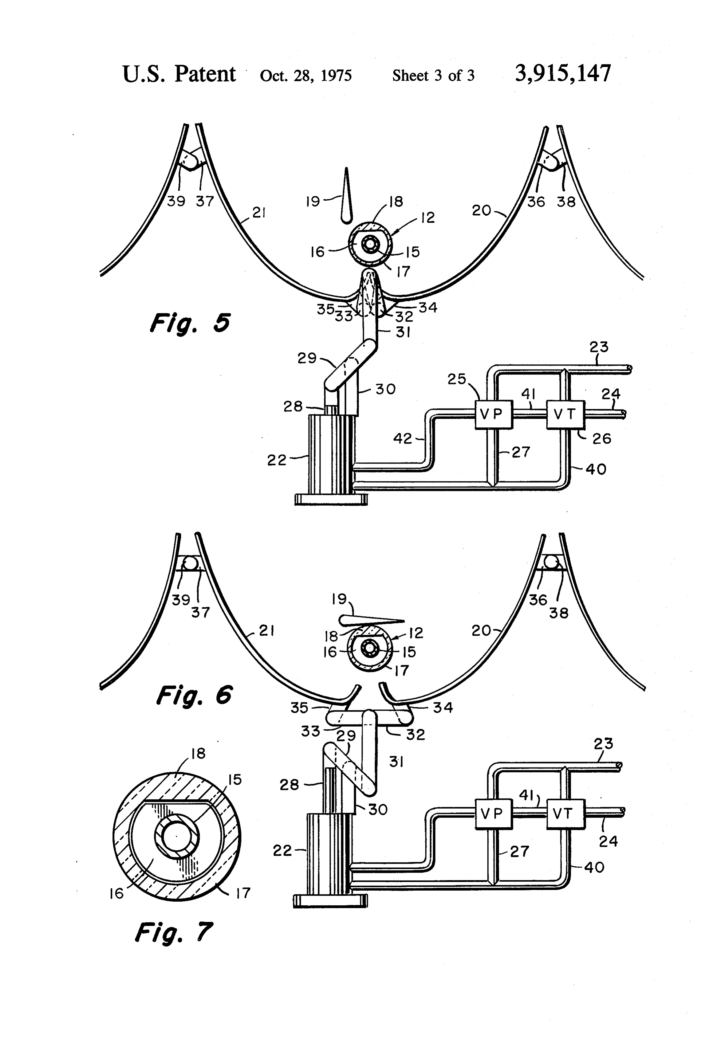
practical, a solar energy system must be both a genera FIG. 4 is a sectional elevation of a modified form of tor and a storage facility for energy. Extended periods the invention from that shown in FIG. 2. of overcast conditions will necessarily reduce the out FIG. 5 is a schematic view showing the relationship put of the system to the point of dependency on it with 15 of the components of the system illustrated in FIG. 1. out energy storage would be precarious. One approach FIG. 6 shows the system illustrated in FIG. 5 in the to the energy storage problem has been the provision de-focused condition.
of a series of batteries that can be charged during peri FIG. 7 is a section on an enlarged scale over that of ods of productivity, and drawn upon during periods in for the5heat-absortion
FIGS. and 6, and illustrating the transparent housing tubes.
which the generator is not sufficiently productive. 20
A common approach in designing these systems has DESCRIPTION OF THE PREFERRED been to provide a circulation within the heat EMBODIMENTS absorption tubes which may be induced either by Referring to the schematic illustration appearing in pumps, or by the action of gravity through causing the FIG. 1, a series of heat-absorption units is indicated at tubes to communicate with the tank at vertically 25 10-13, all of these including a central absorption tube spaced points. An increase in temperature of the liquid in communication with the tank generally indicated at within the tubes provides a reduction in the specific 14. The exterior housing of this tank may be of any gravity of the liquid to the point that the heated liquid convenient configuration, with the liquid-containing is displaced upwardly, with the downflow return to be interior container being designed to accomodate se provided within the tank. It is obvious that any pump 30 lected pressure conditions. The structure associated ing system designed to supplement this action will nec with each of the heat-absorption units is the same, and essarily draw some of the energy that the system gener is best shown in FIGS. 5 and 6. The absorption units ates. center in thin-walled tubes as shown at 15 which are
preferably blackened to increase the heat conversion from the sun's rays. Suitable transverse or axial fins as
The solar energy system provided by this invention shown at 16 may be provided on these tubes to further establishes an energy storage through the use of a increase the heat absorption and position the tubes 15. heavily-insulated tank to which heated liquid is deliv A transparent outer housing 17 surrounds the tubes 15, ered by the absorption tubes to maintain pressure and 40 with the space between the tubes and the housing pref temperature conditions within the tank at predeter erably being evacuated. The upper portion of the tube mined levels. Arrangements are provided to assure that indicated at 18 is provided with a lens-shaped configu the heat-absorption system does not function in the op ration tending to focus the sun's rays on the upper por posite manner to cool the tank contents during over tion posing of the tube 15. A flap 19 is moveable from the ex position shown in FIG. 5 to the shading position cast periods. In one form of the invention, the heat 45 absorption tubes below themselves free of liquid on at of FIG. 6 as a means of controlling the energy trans tainment of a temperature in excess of the boiling point ferred to the tube 15 from the sun's rays which are not of the tank liquid in the tubes at the prevailing pressure, focused by the semi-parabolic reflector sections 20 and and further elevation of the temperature induces a de 21. These are shown in the heating position in FIG. 5, focusing of the reflectors to permit the heat-absorption The inFIG.
and the defocused, or cooling position, in FIG. 6.
5 position places the focus of the parabolic tubes to cool below the condensation point. This action segments 20 produces a pulsing of the tank liquid into and out of the tube 15. and 21 approximately at the axis of the tubes, with the liquid being discharged into the tank at Shifting of the parabolic sections from the focused an elevated temperature, and preferably at an upper position of FIG. 5 to the un-focused position of FIG. 6 level within the tank. Withdrawal of liquid from the 55 is induced by the action of the piston-cylinder actuator tank as the temperature in the tubes falls below a con unit 22 of conventional construction. A pressure line densation point is preferably taken from the cooler 23 and an exhaust line 24 communicate with the actua lower levels in the tank. Another form of the invention tor 22 through either the pressure-responsive valve 25 utilizes a gravity-induced circulation within inclined 60 or the temperature responsive valve 26. The actuator heat-absorption tubes between vertically-spaced posi 22 is biased by an interior spring (not shown) to the tions on the tank, and includes a valve blocking such FIG. 5 position. Attainment of excessive pressure circulation when the tubes would function as a cooling within the tank 14 will cause the pressure-responsive. radiator. The control valve for this arrangement is ei valve 25 to deliver steam or air pressure through the ther temperature-responsive, or a check valve sensitive 65 conduit 27 to move the actuator 22 to the FIG. 6 posi enough to function in response to the reversal of flow tion. The piston 28 rocks the arm 29 in a clockwise di resulting from a cooler liquid being present in the ab rection about its pivotal mounting on the fulcrum 30. sorption tubes than in the tank. This actions pulls downwardly on the link 31, and gen
Page 6
erates a toggle motion of the links 32 and 33 pivotally exclusively inflow to the tank from the heat-absorption connected to the brackets 34 and 35 on the reflector units, thus delivering the heated liquid at the warmer sections 20 and 21. This action results in displacing the portions of the tank, and withdrawing the cooler liquid reflector sections downwardly and outwardly, thus af from the tank during the phase of the cycle in which the fecting the relative position of the focus of curvature absorption units are charged as the temperature falls with respect to the tube 15. This movement is accom below the condensation point. panied by a slight pivoting of the brackets 36 and 37 Referring to FIG. 4, a similar tank assembly 14 is pro (secured to the reflector sections) about the shafts 38 vided with the inclined heat-absorption units 52. These and 39 supported by any convenient fixed structure. are preferably of a 'V' configuration in side elevation Alternatively, this hinging action can be replaced by O in order to provide for heat transfer over the full length simple deflection of the sheet material forming the re on exposure to the sun's rays. The upper and lower in flector sections 20 and 21. clined sections will each be provided with reflector ar The pulsing action causing the flow to move to and rangements of the type shown in FIGS. 5 and 6, al from the tubes 15 into the tank is controlled by the though consideration should be made with regard to temperature-responsive valve 26, which is in heat 15 the placement of the entire assembly to minimize the detecting relationship with one of the tubes. On the in degree to which the upper unit will shade the lower crease in temperature in the tubes to a point above the O.
boiling point of the liquid in the tube at the local pres It is anticipated that the tubes 12 are most convenient sure, the tube will blow itself clear of the liquid, and in four-foot lengths, and approximately 20 of these of discharge its contents into the tank. The absence of liq five/sixteenths of an inch inside diameter would be in uid in the tube will permit the temperature to increase stalled in conjunction with a 500 gallon tank to main rapidly, and activate the valve 26. Pressure is thereby tain a permanent energy delivery of three horse power delivered through the conduit 40 to place the actuator at a 50% solar effect. These tubes should be thin 22 in the FIG. 6 position. The resulting defocusing of walled, and of a highly heat-conductive material such the reflectors 20 and 2 cools the tube 15 below the 25 as silver, copper, or aluminum. This arrangement condensation point, thus returning the valve 26 to a po would allow for long periods of overcast. If desired, the sition in which the actuator 22 can exhaust into the line heat storage within the insulated tank can be supple 24 through the conduit 41. The pressure-responsive mented by the storage of energy in a series of batteries, valve will normally be open to flow to the conduit 41 which can be charged during periods in which the de from the conduit 42. In summary, the un-actuated posi 30 mand by driven equipment was less than the generating tion of the pressure and temperature responsive valves capacity. With proper insulation, the unit appears ca is to permit the biasing action of the actuator 22 to pable of delivering 3 horse power for about 3 days with maintain the FIG. 5 position. On the attainment of ex out the addition of solar energy, if the normal operating cessive pressure in the tank 14, or excessive tempera 35 cut-off pressure in the tank is approximately 100 lbs. ture in the tubes 15, the actuator 22 will de-focus the per square inch. It is preferable to maintain the liquid reflector sections. This de-focusing may be supple in the tank at the temperature of saturated steam at this mented by movement of the flap 19 to the FIG. 6 posi pressure. It is also possible to apply reflectors to the tion where full reduction of temperature of the tubes output of the tank to place the steam in the super 15 is desirable. The lens 18 should be wide enough to 40 heated condition. It is entirely practical to generate focus substantially all the sun rays that are not properly temperature within the tubes 12 on the order of 600 de focused by the reflector sections. The heating effect grees Fahrenheit. To provide this temperatures capa from the lens 18 will also offset a tendency for the top bility, the reflector surface should extend laterally from of the tubes 15 to cool by radiation to the cooler hous the tubes over a projected area 35 times the width of ing 17. the tube.
The board aspect of the function of the valve 26 is 45 To provide the maximum degree of heat-storage ca the detection of the absence of liquid in the tubes 15. pability, it may be desirable to install a heat-sink tank This can also be provided by detecting the deflection or container as shown at 53 in FIG. 4. This container of the tubes. Particularly in the units 10-13 are may be filled with some liquid having a greater specific mounted in cantilever fashion, a defection sensor of 50 heat than that of the liquid within the container portion standard design can register the downward bending of 44 of the tank, and may rest on appropriate abutments the tube assemblies when full as opposed to the posi as shown at 54 supported by the bottom of the tank. In tion when substantially free of the weight of contained this arrangement, the liquid outside the heat-sink con liquid. tainer may be selected for its vaporization characteris Referring to FIG. 2, the tank assembly 14 includes 55 tics exclusively. Water is usable for this function, and the outer housing 43, the inner container tank 44, and the heat-sink liquid can be mercury where the cost is the insulation interposed between the housing and the justified. The heat-sink effects can be further increased tank shown at 45. A steam output line 4.6 may be asso by utilizing a material in the container 53 selected to ciated with a piston engine or a turbine for driving an have a melting point near the boiling point of the work electric generator. Preferably, this arrangement will be 60 ing liquid (at the selected pressure) used in the tubes of the closed-circuit type including a condenser which 15. Where the latter is water, the material in the con will return the condensate through the pipe 47 to the tainer 53 can be lithium or magnesium chloride (Mg injector 48, which returns the liquid to the tank 44. Cl, 6H,O). The heat of fusion of these materials is rel Each of the heat-absorption units preferably commu atively high, and provides a very substantial energy nicates with the tank 44 at vertically-spaced positions. 65 storage. The melting point of the heat-sink material The passage 49 is provided with the check valve 50 per should be withing the range of temperatures encoun mitting exclusively outflow from the tank 44 into the tered during the operation of the working liquid in the heat-absorption units 12. The check valve 51 permits tank so that the release of the latent heat of fusion of
Page 7
the heat-sink material will maintain such temperatures. upper and a lower passage, said upper passage includ To maximize the energy storage for a given space, the ing a check valve permitting flow exclusively into said quality of water may be limited to that required for the tank means, and said lower passage including a check working vapor cycle, with the remainder of the avail valve permitting flow exclusively out of said tank able volume occupied by the heat-sink material in one 5 S.
or more containers 53 in heat-exchanging relationship 3. A generator as defined in claim 1, wherein said de with the water. energizing means includes mechanism adapted to shift | claim: the relative position of said reflector means with re 1. A solar energy steam generator including tank spect to said heat-absorption conduit means primarily means, heat-absorption conduit means communicating 10 at a position on said reflector means adjacent the focus with said tank means, and reflector means operable to thereof, the outer portions of said reflector being focus rays from the sun or said heat-absorption conduit mounted to accommodate said shift. means, wherein the improvement comprises: 4. A generator as defined in claim 3, wherein said re de-energizing means responsive to the absence of liq flector is elongated along a focal axis, and includes sep uid in said heat-absorption conduit means, said de 15 arable substantially symmetrical components normally energizing means being operative to reduce im meeting along a line parallel to and adjacent said focal pingement of sun rays on said conduit means to a axis.
degree sufficient to reduce said temperature to 5. A generator as defined in claim 1, wherein said below the boiling point of said liquid, said de tube contains a lens portion disposed on the opposite energizing means further being operative to tend to 20 side of said conduit means from said reflector means restore said impingement in response to said re and adapted to focus sun rays on said conduit means, duced temperature; and and wherein said conduit means has a plurality of trans a dead-ended tubular member constituting said heat verse fins adapted to absorb heat resulting from im absorbing conduit means, said tubular member and pingement of sun rays, and to locate said conduit de-energizing means cooperating to generate recip 25 means within said tube.
rocating flow of liquid in said tubular member in 6. A generator as defined in claim 5, wherein said de response to said impingement of sun rays as said energizing means includes a shade device movable to liquid is blown out of said tubular member on at and from a position shielding said lens portion from sun tainment of a temperature in excess of the prevail rays.
ing boiling point, and said liquid returns under vac 30 7. A generator as defined in claim 1, wherein said de uum as said de-energizing means operates to cycli energizing means includes valve means responsive to a cally reduce said temperature below the condensa temperature in said heat-absorption conduit means in tion point. excess of the boiling point of said liquid to reduce said 2. A generator as defined in claim 1, wherein said temperature.
conduit means communicates with said tank via an 35 ck x 2k xk
Provenance
- Collection
- Cited prior art
- Original PDF
- patentimages.storage.googleapis.com →
- Filed
- 1973-12-03
- Pages
- 7
- Method
- pdftotext (the PDF's own text layer) + pdftoppm 300dpi page scans
- Source
- Google Patents bibliographic record
- Granted
- 1975-10-28
- Inventors
- Arthur E Rineer
- Transcribed from
- patentimages.storage.googleapis.com →