patent · US2445350
Multiple-effect solar still
20 July 1948
Page 1
July 20, 1948. D. C. GINNINGS 2,445,350
ULTIPLE EFFECT SOLAR STILL
Filed Dec. 23, 1943 2 Sheets-Sheet l
ZealaaZeaZZZZZZZZZZZZZZYZZYaaaaaaaa
ZYaaaaaaaaaaaaaaaaaaaaaaaaZaaaaaaaaaa.
ZZZZZZZZZZZZZZZZYZZYZZZZZZZZZZZZZZZZZZ
C-Saya NS-S-S-S-SSSSN-SaNSSSSSys, SSS
NSNSNSNYSSSSSNSNSNSNSNSNSNSNSSNNSNSNSNSSNSNSNSSNSS
SSSNSSSSSSSayya.
G/mm / wes
41 - AttoRNEY
Page 2
Drawing sheet — no readable text.
Page 3
Patented July 20, 1948
MULTIPLE-EFFECT soLAR stn L
Defoe C. Ginnings, Macomb, III.
Application December 23, 1943, Serial No. 515,352
(Granted under the act of March 3, 1883, as
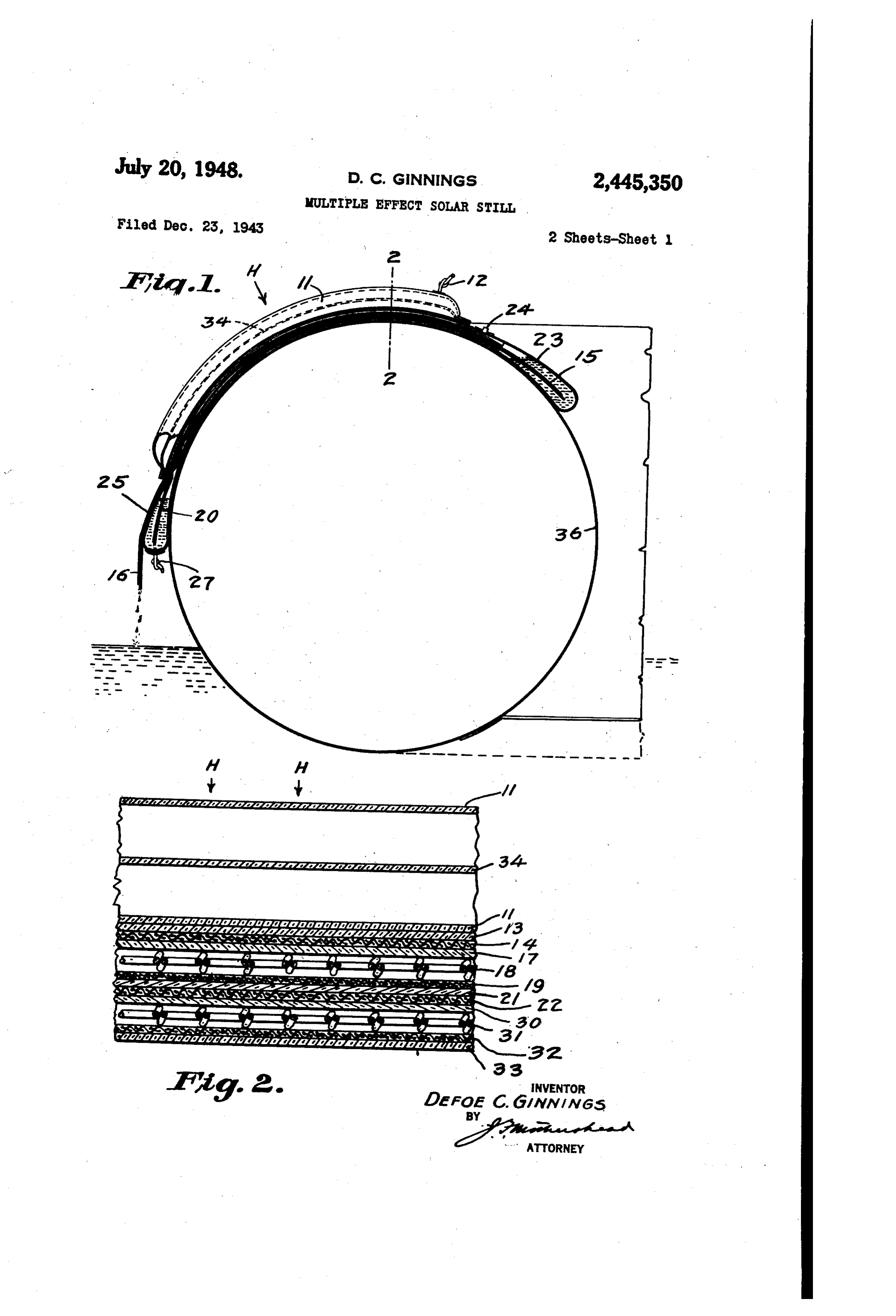
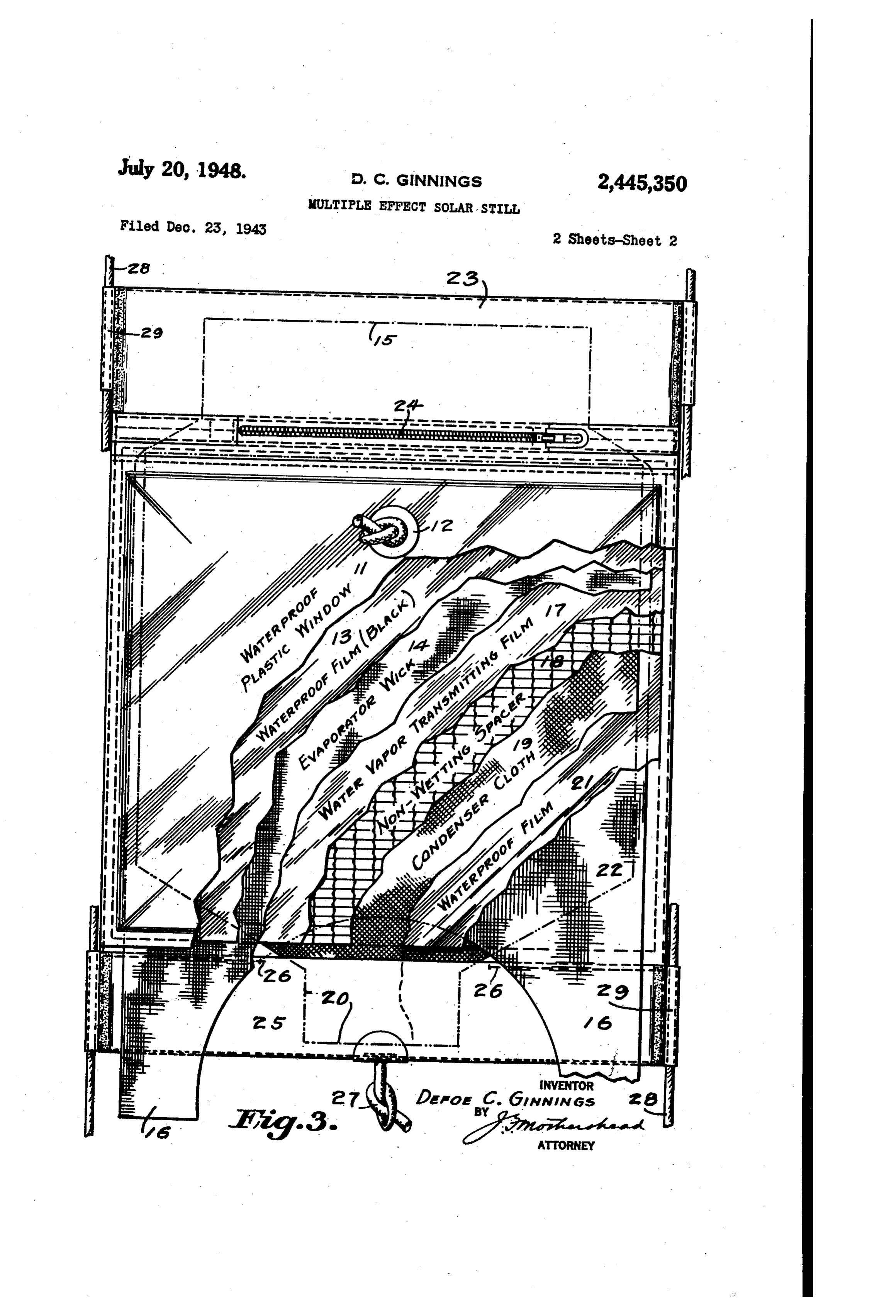
The invention described herein may be manu for inflating the same with air, here shown as a factured and used by or for the Government of flexible tube 2 which may be knotted at will to the United States for governmental purposes prevent the egress of air. A blackened water and without the payment to me of any royalty thereon vapor-proof film 3 is directly beneath the win in accordance with the provisions of the act of 5 dow and may be the underside of an inflatable April 30, 1928 (Ch. 460, 45 Stat. L. 467). bag, of which the window f forms the face and This invention relates to an improved device beneath the film 3 is an evaporator wick 4 hav for distillation, or more specifically, for using ing an extension 5 for transferring a supply of solar heat to distill sea water to obtain potable Sea Water or other non-potable water to and Water. O through the body of the wick, and one or more Prior to my invention, all solar stills of which extensions 6 protruding from the opposite nar I have knowledge have been the single-effect gin of said wick 4. Directly beneath and in type-that is, the energy received from the sun contact with the wick is a water vapor transnit has been used only once for distillation. As a ting film fl and beneath the film T is a non result, efforts to devise solar stills which are ap 15 Wetting spacer 8, here shown as a large mesh plicable to emergency use in rubber life rafts Screen having single strands in one direction have not been very successful because the area, passing through loops of two twisted strands at weight, and complications have been excessive in right, angles thereto. Beneath the spacer 8 is proportion to the water obtainable from them. a layer of Condenser cloth 9 having an extens It is an object of my invention, therefore, to Sion 29 and underlying the main portion of the devise a means of using the sun's energy more cloth 9 is a water and vapor-proof film 2. The than once to distill water, thereby greatly in Waterproof film 2 is in thermal contact with a creasing the amount of water obtainable from a Second evaporator wick 22 of a second still, The given area exposed to sunlight. extension 5 of the wick 4 is enclosed within a It is a further object of my invention to devise Water supply pocket 23 which may be closed' by a a method of decreasing the weight of the solar Zipper 24. The extension 20 of the condensel still to such a degree that its weight is Small in cloth f9 projects into a distillate collectig pocket comparison with the amount of Water it can 25 which may be secured against spreading by distill in a reasonable period. stitching 26. The pocket 25 is provided with a It is a still further object of my invention to 30 drain outlet 27, here shown as a knotted flexibie provide a solar still which occupies little space, tube. For Securing my still against accidental either in storage or in use; has no rigid parts, loss while in use, such as by wind or wave action, and requires the minimum of attention. I provide suitable means for lashing the device It has been the practice in multiple-effect stills in place such as cords 28 fastened by loops 29. to distill in absence of air and vary the total 35 Figure 2 discloses a section of a two-stage still pressure of the distilling material from stage to having two spaced transparent windows, the stage. However, the application of a solar still thicknesses of the layers being magnified for to a life raft practically excludes the multiple clearness. Beneath the wick 22 (Figs; 3 and 2) stage still with total pressure changing from stage there are in order the vapor pervious film 30, the to stage. Therefore, a still has been devised in 40 non-wetting spacer 3, the condenser cloth 32 and which the total pressure has been kept constant the water-and-vapor-proof film 33, thus in this from stage to stage, while the partial pressure of Second and succeeding stages the blackened layer water has been varied. and the plastic window are omitted because In the accompanying drawings: neither wouldthrough assist in the efficient use of the
Figure 1 is an elevation partly in section, as it 45 heat passing the first still. may be positioned upon a rubber life raft; Figure 1 illustrates my method of causing a Figure 2 is an enlarged section on the line 2-2 gradual flow of salt water from the supply pocket of Figure 1, of a two-stage still having tWo spaced through the wick to flush out the concentrated transparent windows; salts which would otherwise slow down the supply Figure 3 is a plan of a two-stage still having a 50 of water below the requirements of my still and single plastic window, the plastic window and in time substantially stop the supply of water other underlying layers being broken away to dis vapor. This is accomplished by providing for a close the underlying structure. gravity assisted discharge of concentrated salt In these drawings (see Fig. 3), fi represents water through the Wick extensions 6 which are a waterproof plastic window provided with means 5 kept substantially lower than the supply of salt
Page 4
3 (Fig. 3). The plastic windows water. In my multiple-stage still a single Salt mediate air spaces transmit most with their inter water pocket may supply water to a plurality of energy to 13, but prevent. excessive oflosstheupward
stills and the distillate may also be collected in a of the heat produced at 3. These window single distillate collecting pocket 25.
The basic principles of operation of my mul Storagebags 5 faced when may be deflated to permit compact not in use.
tiple-effect still are illustrated in Figs. 2 and 3. Layer 3, in addition to converting the Sun's In the first stage of this still, a source of heat H rays to heat, is impermeable to both liquid and causes distillation of water from 4 to an absorb ent layer f9 on which the water condenses. The O passes water.
vapor The heat thus produced in 3 two absorbing layers 4 and 9 are separated by the rubber life the through multiple-effect still, through a non-wetting mesh spacer 8 which holds the transmitted to the seatube raft 36, and is eventually water and air. In pass two layers apart, but is mostly open to allow ing through the still, this heat produces distilled diffusion of water vapor through air from 4 . water in each of the stages in the manner pre
The heat of condensation of the water on 9 in 5 viously described.
The sea water is held in the pocket 23 and the first stage is transmitted to a Second still flows through the evaporator layers 4 in the through the waterproof layer 2, to a second layer 22 which is wet with salt water. This same heat still ends by capillary and syphon action. The top of the evaporator layers 5 from all the causes distillation of water from 22 to a second condenser layer 32 (Fig. 2) which absorbs the 20 stages the extend into the sea water pocket 23, while bottom ends 6 - extend down to a lower water condensed in the second stage. A water level than the salt water supply to provide drain proof film base 33 underlies the condenser layer age of the concentrated sea water from the bot 32. ton ends 6. In this manner, the formation The heat of condensation of the water in 32 of of solid salt in the evaporating layers in the the second stage may similarly be used in a third still25 is avoided and the high efficiency of the stage, and as many stages as may be deemed still is maintained by providing a gradual dis practicable. charge of concentrated salt water and maintain As an aid to keeping the spacer to a minimum thickness, it was found desirable, but not neces 30 ing is during evaporation a sea water supply which not too concentrated.
sary, to introduce between the absorbent layer 4 and the non-wetting spacer 8, the layer it. is The water distilled in the multiple-effect still collected in the condenser layers 9 and flows
This layer consists of a thin film of a material by capillary and syphon action to the bottom such as regenerated cellulose which freely trans mits water vapor, but which presents a reason 85 end 20 of the condenser layer 9 into the pocket 25 which holds the distilled water.
ably dry surface next to the non-Wetting spacer. The plan of the multiple-effect solar still is The theory of operation of the one stage of the shown in Figure 3. The still is assembled on a still is as follows: The transfer of heat from the "evaporator' layer 4 to the 'condenser' layer 9 plastic film base 33 indicated by full lines. A pocket 23 is made in the top end to hold the is accomplished by distillation of water, and by sea water which is introduced by opening the radiation, conduction, and convection. The de sign of the still is such that the heat transfer end is 24.zipper A second pocket 25 at the bottom made to hold the distilled water.
by distillation is large in comparison with all other The top ends 5, of the evaporator layers 4, heat transfer. This allows a high efficiency. consisting of textile material such as a thin fian By making the distance between 4 and 9 nel cloth, extend into pocket 28. The bottom small, the convective and radiant heat transfer 45. ends, become negligible in comparison with the heat so that6,theofconcentrated the evaporator layers are shaped sea water drains away transfer by distillation and by conduction. The from the center and drips off. The bottom ends, heat transfer by distillation is made large com 20, of the condenser layers 9, also thin textile pared to that by conduction by several means. 50 material, extend into the pocket 25 and are First, the amount of solid material in the sepa designed to bring the distilled water to the rator 8 between 4 and 9 is kept to the mini center. A drain outlet 27 in the pocket 25 is mum required for avoiding contact of 7 and 9 used in removing the distilled water. or bridging the gap by surface tension. In this The evaporator and condenser layers are sepa Way the Solid conduction is minimized.
Second, the separator 8 and layer T are made 55 rated in each stage as shown in Figure 2 by a plastic screen spacer 3f, and a layer 30 of such as nonwetting as possible so that the liquid water material as regenerated cellulose which freely does not bridge the gap between 7 and 9 by transmits water vapor. Between successive Surface tension. In this way the liquid conduc stages is a thin layer of waterproof material tion is minimized.
Third, the still is operated at such a tempera Such 60 as Winylite or Pliofilm which does not allow ture that the heat transfer by distillation is the Seaofwater mixing the condensed water in one stage with in the next stage.
large in comparison with the heat transfer by On top of the assembly of the several stages conduction through the air and other materials between the layers and 9. Increase in the of the still are located the plastic windows. The operational temperature of the still greatly in 65 space between these windows may be inflated creases the vapor pressure of water which causes while in use to conserve Solar heat. The edges distillation. However, increase in temperature foundationwindows of these of the may be sealed to the plastic still, thus forming one con has only slight effect on the thermal conductivity plete unit which may be rolled compactly for of materials.
The use of the construction principles previ 70 storage. v.
It should be understood that the present dis ously described, in a solar still to be used on rubber life rafts is shown in Figure 1. The still closure and is for the purpose of illustration only, that the invention includes all modifica is supported by the rubber life raft tube 36. The tions and equivalents which fall within the scope sun's rays H are transmitted through the plastic windows f and are absorbed on the black layer 75 of the appended claims,
Page 5
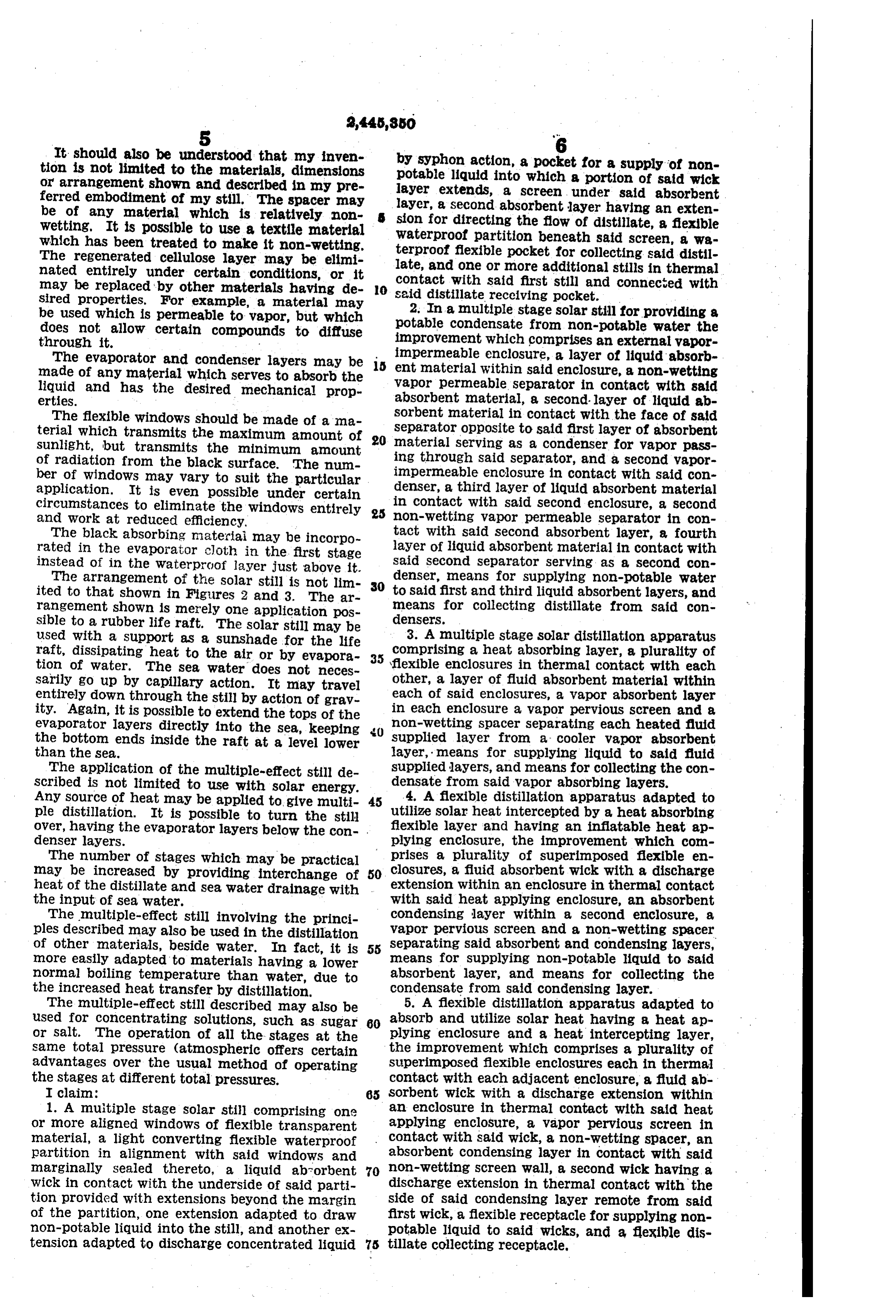
It should also be understood that my inven by Syphon action, a pocket for a supply of non tion is not limited to the materials, dimensions potable liquid into which a portion of said wick or arrangement shown and described in my pre layer extends, a screen under said absorbent ferred embodiment of my still. The spacer may layer, a second absorbent layer having an exten be of any material which is relatively non
Wetting. It is possible to use a textile material sion for directing the flow of distillate, a flexible Waterproof partition beneath said screen, a wa which has been treated to make it non-wetting. terproof flexible pocket for collecting said distill The regenerated cellulose layer may be elimi nated entirely under certain conditions, or it late, and one or more additional stills in thermal may be replaced by other materials having de Contact with said first still and connected with O said distillate receiving pocket.
sired properties. For example, a material may 2. In a multiple stage solar still for providing a be used which is permeable to vapor, but which potable condensate from non-potable water the does not allow certain compounds to diffuse through it. improvement which comprises an external vapor The evaporator and condenser layers may be impermeable enclosure, a layer of liquid absorb made of any material which serves to absorb the ent material within said enclosure, a non-wetting liquid and has the desired mechanical prop vapor permeable separator in contact with said erties. absorbent material, a second-layer of liquid ab The flexible windows should be made of ama Sorbent material in contact with the face of said terial which transmits the maximum amount of 920 separator opposite to said first layer of absorbent material Serving as a condenser for vapor pass
Sunlight, but transmits the minimum amount ing through Said Separator, and a second vapor of radiation from the black surface. The num ber of windows may vary to suit the particular impermeable enclosure in Contact with Said con application. It is even possible under certain denser, a third layer of liquid absorbent material circumstances to eliminate the windows entirely 25 in contact with said second enclosure, a second non-wetting vapor permeable separator in Con and work at reduced efficiency,
The black absorbing materiai may be incorpo tact with said second absorbent layer, a fourth layer of liquid absorbent material in contact with rated in the evaporator cloth in the first stage said instead of in the waterproof layer just above it. second separator Serving as a second Con The arrangement of the solar still is not lim 30 denser, means for supplying non-potable water ited to that shown in Figures 2 and 3. The ar to said first and third liquid absorbent layers, and means for collecting distillate from said Con rangement shown is merely one application pos densers.
sible to a rubber life raft. The solar still may be 3. A multiple stage solar distillation apparatus used with a Support as a sunshade for the life comprising a heat absorbing layer, a plurality of raft, dissipating heat to the air or by evapora. 35 \flexible enclosures in thermal contact with each tion of water. The sea water does not neces
Sarily go up by capillary action. It may travel other, a layer of fluid absorbent material within entirely down through the still by action of grav each of said enclosures, a vapor absorbent layer ity. Again, it is possible to extend the tops of the in each enclosure a vapor pervious screen and a evaporator layers directly into the sea, keeping non-wetting spacer separating each heated fluid the bottom ends inside the raft at a level lower supplied layer from a cooler vapor absorbent than the sea. layer, means for supplying liquid to said fluid The application of the multiple-effect still de supplied layers, and means for collecting the con Scribed is not limited to use with solar energy. densate from said vapor absorbing layers. Any Source of heat may be applied to give multi 45 4. A flexible distillation apparatus adapted to ple distillation. It is possible to turn the still utilize solar heat intercepted by a heat absorbing Over, having the evaporator layers below the con- . flexible layer and having an inflatable heat ap denser layers. plying enclosure, the improvement which com The number of stages which may be practical prises a plurality of superimposed flexible en may be increased by providing interchange of 50 closures, a fluid absorbent wick with a discharge heat of the distillate and sea water drainage with extension within an enclosure in thermal contact the input of sea water. with said heat applying enclosure, an absorbent The multiple-effect still involving the princi condensing layer within a second enclosure, a ples described may also be used in the distillation vapor pervious screen and a non-wetting spacer of other materials, beside water. In fact, it is 55 separating said absorbent and condensing layers, means for supplying non-potable liquid to Said more easily adapted to materials having a lower normal boiling temperature than water, due to absorbent layer, and means for collecting the the increased heat transfer by distillation. condensate from said condensing layer. The multiple-effect still described may also be 5. A flexible distillation apparatus adapted to used for concentrating solutions, such as sugar 60 absorb and utilize solar heat having a heat ap or salt. The operation of all the stages at the plying enclosure and a heat intercepting layer, same total pressure (atmospheric offers certain the improvement which comprises a plurality of advantages Over the usual method of operating superimposed flexible enclosures each in thermal the stages at different total pressures. contact with each adjacent enclosure, a fluid ab I claim: 65 sorbent wick with a discharge extension within 1. A multiple stage solar still comprising one an enclosure in thermal contact with Said heat or more aligned windows of flexible transparent applying enclosure, a vapor pervious screen in material, a light converting flexible waterproof contact with said wick, a non-wetting spacer, an partition in alignment with said windows and absorbent condensing layer in contact with said marginally sealed thereto, a liquid abrorbent 70 non-wetting screen wall, a second wick having a wick in contact with the underside of said parti discharge extension in thermal contact with the tion provided with extensions beyond the margin side of said condensing layer remote from Said of the partition, one extension adapted to draw first wick, a flexible receptacle for Supplying non non-potable liquid into the still, and another ex potable liquid to said wicks, and a flexible dis tension adapted to discharge concentrated liquid 75 tillate collecting receptacle,
Page 6
7 UNITED STATES PATENTs 6. A multiple stage solar distillation apparatus
Comprising a plurality of flexible enclosures in Number Name Date each thermal contact with a successive enclosure, 552,456 Theisen ------------ Dec. 31, 1895 the first of said enclosures being inflatable and 1,703,44. Van Brunt ---------- Feb. 28, 1929 having a Solar heat absorbing layer, a vapor Dooley ------------ June 30, 1931 pervious screen and a non-wetting separating 5 1812,516 1,881,041 Benjamin ----------- Oct. 4, 1932 spacer in each enclosure, an absorbent wick with 1,958,547 Payne ------------- May 15, 1934 a discharge extension in the heated side of each 2,117,802 Hickman ---------- May 17, 1938 of said enclosures and a layer of vapor absorbent Waterman --------- May 23, 1939 material in the cooler side of each enclosure, a 28393
pocket for Supplying non-potable water to each 2,412,466 Miller ------------- Dec. 10, 1946 of said wicks, and a pocket for collecting and 2,413,101 Delano ------------- Dec. 24, 1946 holding distillate from said condensing layers FOREIGN PATENTs each vapor condensing layer serving to transmit heat to a succeeding enclosure. 15 Number Country Date DEFOE. C. GINNINGS, 11,350 Great Britain -------------- 1889
REFERENCES CTED 37,213 Norway ----------- June 25, 1923 The following references are of record in the
Provenance
- Collection
- Cited prior art
- Original PDF
- patentimages.storage.googleapis.com →
- Filed
- 1943-12-23
- Pages
- 6
- Method
- pdftotext (the PDF's own text layer) + pdftoppm 300dpi page scans
- Source
- Google Patents bibliographic record
- Granted
- 1948-07-20
- Inventors
- Defoe C Ginnings
- Transcribed from
- patentimages.storage.googleapis.com →