(350)
Air Management System
Where it is first named
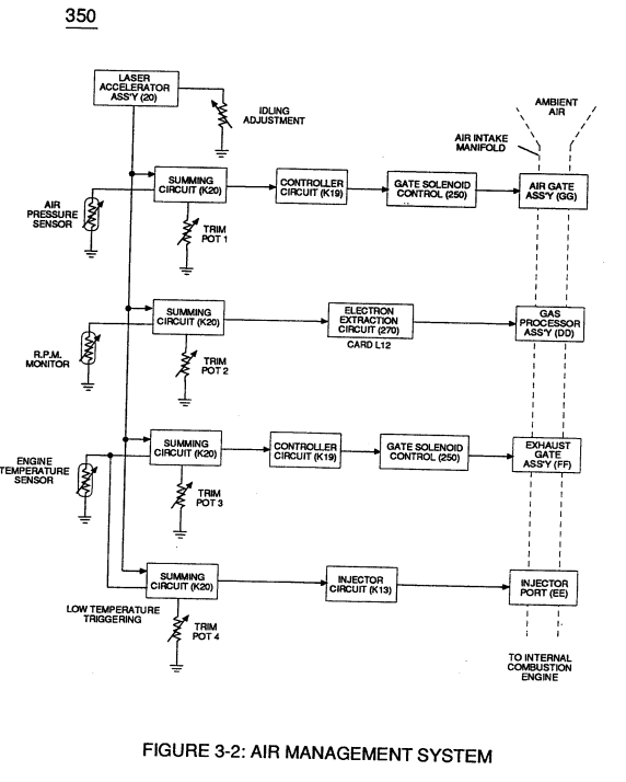
Interlocking Laser Accelerator output {JJ) with Laser Distributor output (HH) of Figure (3-1) causes Fuel-Injectors (36) to be "Tuned" with both Air Management System (350) of Figure (3-2) and Hydrogen Gas Control Circuit (100) of Figure (3-5) to maintain constant Fuel-mixing Ratio (290) of Figure (3-3) during engine performance.
How it is written
- (350) 1×
Drawings 9
-
Carries this number · Laser Accelerator Assembly
-
Figure (3-1) · Voltage Amplitude Control Circuit (50)
-
To further prevent voltage fluctuation during resonant action, Phase Lock Loop technique of Pulse Indicator circuit (110) is utilized during pulsing operations. · Resonant Action
-
Figure (3-1) · Laser Distributor
-
Figure (3-2) · Laser Distributor
-
Hydrogen Fuel-Gas Assembly (450) of Figure (3-1) · Operational Parameters
-
Carries this number · WFC 422DA - Illustrations
-
Carries this number · WFC 422DA - Illustrations
-
3-2 (VIC) Coil Assembly · Voltage Intensifier Coil Assembly
Where it is named · 1
Laser Distributor 1×
-
Air Management System (350)
Interlocking Laser Accelerator output {JJ) with Laser Distributor output (HH) of Figure (3-1) causes Fuel-Injectors (36) to be "Tuned" with both Air Management System (350) of Figure (3-2) and Hydrogen Gas Control Circuit (100) of Figure (3-5) to maintain constant Fuel-mixing Ratio (290) of Figure (3-3) during engine performance.