Figure (3-3)
Hydrogen Gas Management Performance Curve
How it is written
- (3-3) 1×
Drawings 2
-
Captioned as this figure · WFC 422DA - Illustrations
-
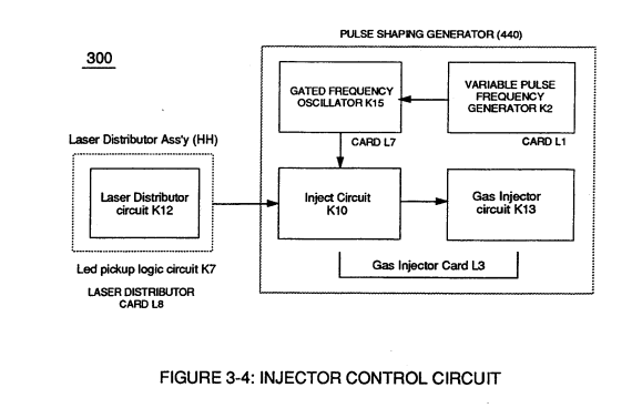
Figure (3-4) · Laser Distributor
On this figure 1
Where it is named · 1
Laser Distributor 1×
-
Interlocking Laser Accelerator output {JJ) with Laser Distributor output (HH) of Figure (3-1) causes Fuel-Injectors (36) to be "Tuned" with both Air Management System (350) of Figure (3-2) and Hydrogen Gas Control Circuit (100) of Figure (3-5) to maintain constant Fuel-mixing Ratio (290) of Figure (3-3) during engine performance.