Figure (3-9)
LED Pickup Circuit J
Also written LED Pickup Circuit · VIC Mount Base
How it is written
- (3-9) 18×
Drawings 3
-
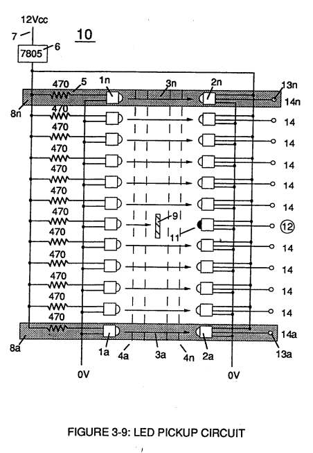
Led Pickup Circuit (10) of Figure (3-9) · Laser Accelerator Assembly
-
Captioned as this figure · WFC 422DA - Illustrations
-
Captioned as this figure · Voltage Intensifier Coil Assembly
On this figure 12
- 1 Negative Charged Hydrogen Electron
- 2 Optoschmitt
- 3 Proton
- 4 Electrical Tension
- 6 Liquefied Ambient Air Gases
- 8 Optical Circuits
- 9 Light-Gate
- 10 Led Pickup Circuit
- 12 Logic-Point
- 13 High-State Logic
- 30 Circuit
- 310 Gas logic circuit
Where it is named · 18
Laser Accelerator Assembly 14×
-
SDP8611 Optoschmitt light receiver (2) of Figure (3-9)
-
The peak wavelength (3) of Figure (3-9) being transmitted from the infrared emitting diode (led) (1) to the Optoschmitt receiver (2) is typically (935 nm) and allows the Optoschmitt (2) clock frequency (the speed by which the Optoschmitt changes logic state) to be (100 kHz).
-
Optical lens (4) of Figure (310) redirects and focuses the transmitted light source (3) of Figure (3-9) (traveling infrared light waves) to the Optoschmitt (2) by passing the light source through a series of concentric lenses (4a xxx 4n) of Figure (3-10) which become progressively smaller from the outer peripheral lens surface (4a) to the inner lens surface (4n).
-
The Derate linearly of light intensity is approximately 1.25mWj degree C above 25 degree C at a spatial distance of .500 inches between the two infrared devices (1)(2) of Figure (3-9) as to Figure (3-10).
-
Together, the matched infrared devices (1)(2) with optical lens (4) forms optical circuit (8) of Figure (3-9).
-
Grouping additional optical circuits (8a xxx 8n) in an inline or linear arrangement, now, forms Led Pickup Circuit (10) of Figure (3-9), as shown in Figure assembly (20) of Figure (3-10).
-
Led Pickup Circuit (10) of Figure (3-9)
-
To perform a switch-logic function, light - gate (9) of Figure (3-9) as to Figure (3-10) is inserted between the matched infrared devices (1)(2) and moved in a linear displacement from one optical circuit (8x) to another optical circuit (8xx), as illustrated in Figure (3-9)(3-10) as to Figure (3-7).
-
To perform a switch-logic function, light - gate (9) of Figure (3-9) as to Figure (3-10) is inserted between the matched infrared devices (1)(2) and moved in a linear displacement from one optical circuit (8x) to another optical circuit (8xx), as illustrated in Figure (3-9)(3-10) as to Figure (3-7).
-
Reversing the direction of the light-gate (9) once again reinstates the original sequential switching order, as illustrated in Figure (3-7) and Figure (3-9).
-
Longevity and reliability of component life is typically 100,000 hours since led pickup circuit (10) of figure (3-9) utilizes no mechanical contacts to perform the sequential logic switch function.
-
Disconnection of power supply (6) to Optoschmitt array (2a xxx 2n) of Figure (3-9) results in a similar "shut down" condition to control circuit (200), as further shown in Figure (3-1).
Acceleration Control Circuit (30) 4×
-
Moving light-gate (9) of figure (3-9) in direct relationship to the physical placement of optical circuits (8a xxx 8n), sets up a time variable (14a xxx 14n) of Figure (3-7) from optical circuits (8x) to another optical circuit (8xx) and …
-
Figure (3-9)
-
Since Led Pickup Circuit (10) of Figure (3-9) operates up to 100 kHz range or above, electrical sensitivity of Opto-circuit (8) provides a instantaneous response to Driver's acceleration, de-acceleration, or cruise control demands.