(2) · also written as a run, 2a xxx 2n
Optoschmitt
Also written SDP8611 Optoschmitt light receiver · Optoschmitt receiver · Optoschmitt array
Where it is first named
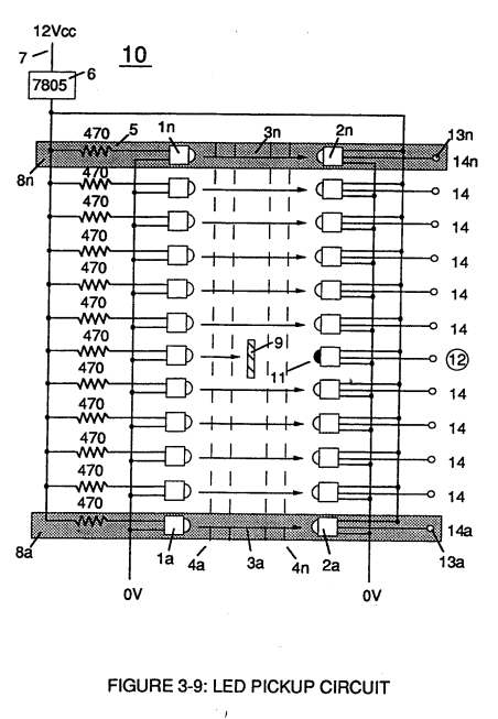
… 10) of Figure (4) which is a component part of Laser Accelerator Assembly (20) of Figure (3-10) uses a GaAs infrared emitting diode (1) of figure (3-9) to trigger a SDP8611 Optoschmitt light receiver (2) of Figure (3-9) from quiescent state ( output logic high ... …
How it is written
- (2) 6×
- (11-2c) 1× with (11) Energy Aperture
- (2a xxx 2n) 1×
2a xxx 2n is Meyer's shorthand for a run of the same thing: 2a is the first, 2n the last, and the x's stand for however many lie between. Every stage of the run is this one numeral. A pair before the letters, 583/602a, is a run of two things that go together, one of each per stage.
Drawings 46
-
The Electron Extraction Process (BB) is, hereinafter, called "The GAS RESONANT CAVITY," as illustrated in Figure 1-7 as to Figure 20JX. · Electron Extraction Process
-
The Resonant Frequency (F) of an LC circuit in series is given by (Eq 4) · LC Circuit
-
The Positive Electrical Voltage Field (E3) and Negative Electrical Voltage Fields (E4) are triggered "Simultaneously" during the same duty-pulse. · Electron Extraction Process
-
Toggling action at full-scale deflection (13a xxx 13n) occurs in the range of (10) kHz or above and thus, allows instant response to driver's acceleration demands. · Acceleration Control Circuit (30)
-
Carries this number · WFC 422DA - Illustrations
-
3-8 Multi-Coil Spool · Voltage Intensifier Coil Assembly
-
Carries this number · Voltage Intensifier Coil Assembly
-
Carries this number · Voltage Intensifier Coil Assembly
-
Carries this number · Voltage Intensifier Coil Assembly
-
3-14 WFC Voltage Ignition Wire · Voltage Intensifier Coil Assembly
-
Carries this number · Electronic Circuit Design
-
Carries this number · Electronic Circuit Design
-
Carries this number · Electronic Circuit Design
-
(170) of Figure (13) · Water Fuel Injector (Taper Resonant Cavity Chamber)
-
(170) of Figure (13) · Water Fuel Injector (Taper Resonant Cavity Chamber)
-
Fluid Displacement Pump (170) of Figure (13) · Water Fuel Injector (Taper Resonant Cavity Chamber)
-
(220) of Figure (18) · Water Fuel Injector (Taper Resonant Cavity Chamber)
-
Carries this number · Water Fuel Injector (Taper Resonant Cavity Chamber)
-
The Following Page 1-7 was not available · Water Fuel Injector (Taper Resonant Cavity Chamber)
-
Carries this number · Steam Resonator Assembly
-
Figure (4-8) · Water Fuel Injection System - Page 2
-
(100) of Figure (4-8) · Voltage Intensifier Coil-Assembly
-
"Electron Bounce" phenomenon (700) of Figure (7-9) · Inductance Reactance (Rs - Cd - FL)
-
(100) of Figure (4-8) · Capacitance Reactance
-
Figure (10-3 A/B) · Propagating Electrical Stress
-
(990) of Figure (10-3) · Propagating Electrical Stress
-
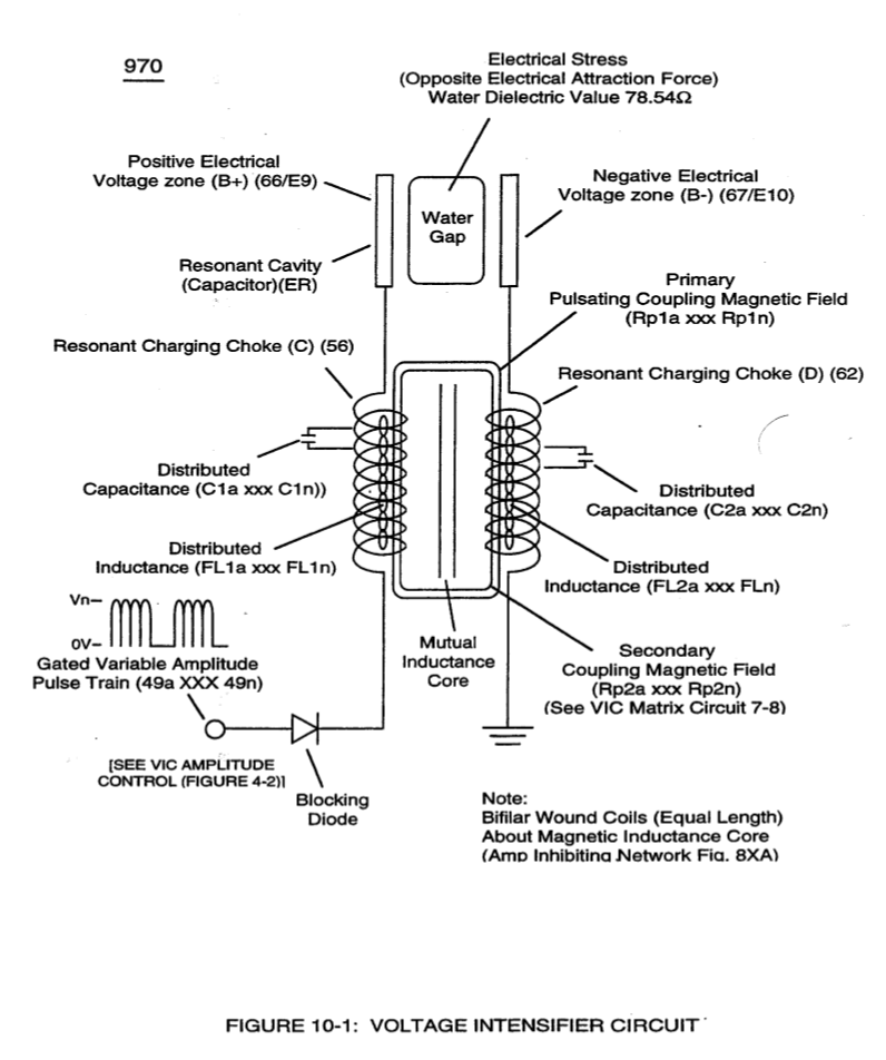
The programmable pulse-frequency (49a xxx 49n) of Figure (10-1) input is simply adjusted to tune-in to the dielectric property of the Water Molecule. · Propagating Electrical Stress
-
Carries this number · Voltage to Amp Differential Ratio
-
Figure (10-3A) · Voltage to Amp Differential Ratio
-
Carries this number · WFC 429 - Illustrations
-
Carries this number · WFC 429 - Illustrations
-
Carries this number · WFC 429 - Illustrations
-
Carries this number · WFC 429 - Illustrations
-
Carries this number · Wobbling Effect
-
Carries this number · WFC 430-2 Illustrations
-
dual unipolar voltage pulse circuit (1010) of Figure (11-1) · Voltage Flexing Process
-
(1030) of figure (11-3) · Voltage Flexing Process
-
voltage intensifier circuit (990) of Figure (10-3) · VIC Switchover Circuit
-
(970) of Figure (10-1) · VIC Switchover Circuit
-
Differential Voltage Wave-Guild (1040B) · Electrical Crossover Switching Circuit
-
Led Pickup Circuit (10) of Figure (3-9) · Laser Accelerator Assembly
-
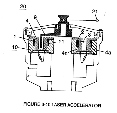
Light-gate (9) integrated with led pickup circuit (10) make up Laser Accelerator assembly (20), as shown in Figure (3-10). · Laser Accelerator Assembly
-
Laser Accelerator (20) of Figure (3-10) · Laser Distributor
-
The figure it sits on · WFC 422DA - Illustrations
-
The figure it sits on · WFC 422DA - Illustrations
-
The figure it sits on · Voltage Intensifier Coil Assembly
Where it is named · 8
Laser Accelerator Assembly 7×
-
SDP8611 Optoschmitt light receiver (2)
… 10) of Figure (4) which is a component part of Laser Accelerator Assembly (20) of Figure (3-10) uses a GaAs infrared emitting diode (1) of figure (3-9) to trigger a SDP8611 Optoschmitt light receiver (2) of Figure (3-9) from quiescent state ( output logic high ... …
-
SDP8611 Optoschmitt light receiver (2)
SDP8611 Optoschmitt light receiver (2) of Figure (3-9)
-
Optoschmitt receiver (2)
The peak wavelength (3) of Figure (3-9) being transmitted from the infrared emitting diode (led) (1) to the Optoschmitt receiver (2) is typically (935 nm) and allows the Optoschmitt (2) clock frequency (the speed by which the Optoschmitt changes logic state) to be (100 kHz).
-
Optoschmitt (2)
The peak wavelength (3) of Figure (3-9) being transmitted from the infrared emitting diode (led) (1) to the Optoschmitt receiver (2) is typically (935 nm) and allows the Optoschmitt (2) clock frequency (the speed by which the Optoschmitt changes logic state) to be (100 kHz).
-
Optoschmitt (2)
Optical lens (4) of Figure (310) redirects and focuses the transmitted light source (3) of Figure (3-9) (traveling infrared light waves) to the Optoschmitt (2) by passing the light source through a series of concentric lenses (4a xxx 4n) of Figure (3-10) which become progressively smaller from the outer peripheral lens surface (4a) to the inner lens surface (4n).
-
Optoschmitt (2)
The spatially concentric lenses (4a xxx 4n) of Figure (3-10) causes the beam angle of the light source to trigger the Optoschmitt (2) beyond the minimum irradiance that is needed to switch the Optoschmitt from quiescent state (high logic state I B+ ) to on-state (output changing to zero volts).
-
Optoschmitt array (2a xxx 2n)
Disconnection of power supply (6) to Optoschmitt array (2a xxx 2n) of Figure (3-9) results in a similar "shut down" condition to control circuit (200), as further shown in Figure (3-1).
VIC Switchover Circuit 1×
-
Voltage intensity (952/953) is, therefore, directly determined by the number of turns of each coil (957/958) as to the applied voltage amplitude of incoming pulse-wave ( ... xxx Vn) (1060) of Figure (11-2c).