(200)
Hydrogen Gas Control Circuit
Also written control circuit · Hydrogen Gas Management System · hydrogen injector system
Where it is first named
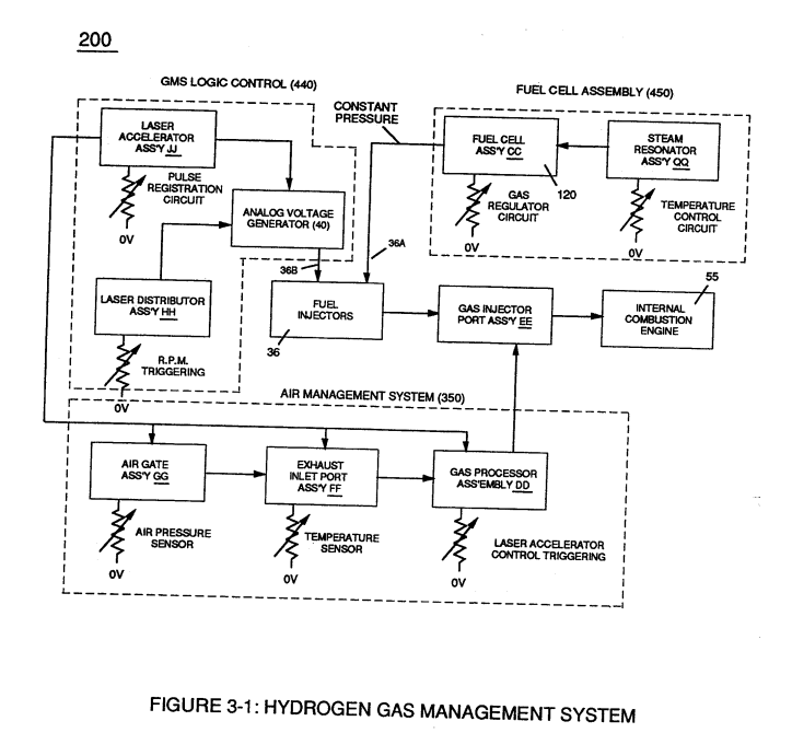
If light emitting diodes (led) (la xxx In) of figure (8) are electrically disconnected from D.C. power supply (6), then Led Pickup Circuit (10) outputs are switch to "low" logic state (l2a xxx 12n) which disallows "low" logic state signal (12), resulting in a "shut-down" condition to Hydrogen Gas Control Circuit (200) of Figure (3-1).
How it is written
- (200) 5×
Drawings 26
-
Carries this number · Laser Accelerator Assembly
-
Figure (3-1) · Voltage Amplitude Control Circuit (50)
-
To further prevent voltage fluctuation during resonant action, Phase Lock Loop technique of Pulse Indicator circuit (110) is utilized during pulsing operations. · Resonant Action
-
(340) of Figure (3-38) · Gas Modulator Process
-
(340) of Figure (3-38) · Gas Modulator Process
-
engine cylinder (102) of Figure (3-38) · Gas Processor
-
Figure (3-1) · Laser Distributor
-
Hydrogen Fuel-Gas Assembly (450) of Figure (3-1) · Operational Parameters
-
Carries this number · WFC 422DA - Illustrations
-
Carries this number · WFC 422DA - Illustrations
-
Carries this number · Water Fuel Injection System
-
3-4 Inner Core Bobbin · Voltage Intensifier Coil Assembly
-
3-5 Outer Core Bobbin · Voltage Intensifier Coil Assembly
-
3-8 Multi-Coil Spool · Voltage Intensifier Coil Assembly
-
Carries this number · Electronic Circuit Design
-
Carries this number · Electronic Circuit Design
-
Carries this number · Differential Air-Gas Inlet Control
-
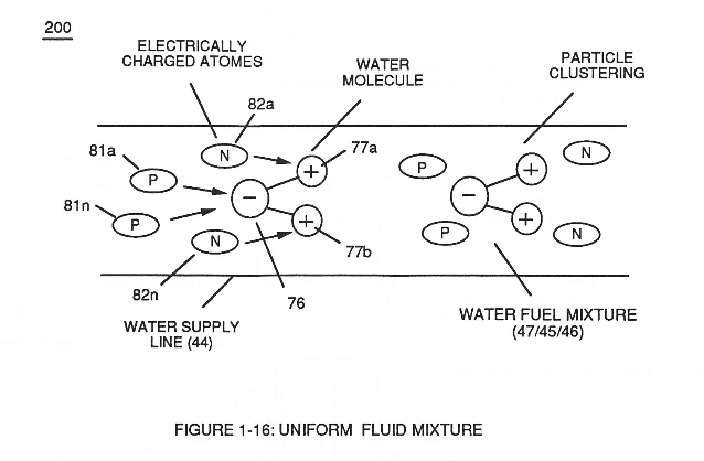
...positive charged gas particles (81a xxx 81n) being directed to and attached to negative charged oxygen atom (76) of water molecule (47); · Water Fuel Injector (Taper Resonant Cavity Chamber)
-
thereby, attenuating voltage amplitude (voltage intensity) beyond Secondary Coil (53) voltage levels (71), as illustrated in (220) of Figure (18). · Funneling Effect
-
2-5 Clamp Nut Assembly · Water Fuel Injector Illustrations
-
Carries this number · Steam Resonator Assembly
-
Carries this number · Steam Resonator Assembly
-
Carries this number · Steam Resonator Assembly
-
Carries this number · Steam Resonator Assembly
-
Carries this number · Steam Resonator Assembly
-
Carries this number · Water Fuel Injection System - Page 1
Where it is named · 5
Laser Accelerator Assembly 2×
-
Hydrogen Gas Control Circuit (200)
If light emitting diodes (led) (la xxx In) of figure (8) are electrically disconnected from D.C. power supply (6), then Led Pickup Circuit (10) outputs are switch to "low" logic state (l2a xxx 12n) which disallows "low" logic state signal (12), resulting in a "shut-down" condition to Hydrogen Gas Control Circuit (200) of Figure (3-1).
-
control circuit (200)
Disconnection of power supply (6) to Optoschmitt array (2a xxx 2n) of Figure (3-9) results in a similar "shut down" condition to control circuit (200), as further shown in Figure (3-1).
Gas Modulator Process 1×
-
hydrogen injector system (200)
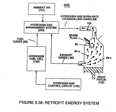
The liberated and cooled exhaust gases (99) is, now, directed to hydrogen injector system (200) which systematically meter-mixes and superimposes a predetermined amount of non-burnable gases (99) of Figure (3-38) onto incoming ambient air gases (101) which is being directed to engine cylinder ( …
Laser Distributor 1×
-
Hydrogen Gas Management System (200)
Rotating light-gate triggering circuit assembly (430) sequentially activates Pulse Shaping Generator (440) of Figure (3-4) to produce a constant 50% Duty-cycle Pulse-Train (see Figure 3-16 once again) to Analog voltage Generator (40) of Hydrogen Gas Management System (200) of Figure (3-1) as to Figure (3-5).
Water Fuel Injector (Taper Resonant Cavity Chamber) 1×
-
while, during the same interim period of time, negative charged gas particles (82a xxx 82n) being directed onward to and affix themselves to positive charged hydrogen atoms (77a / 77b), as illustrated in (200) of Figure (16).