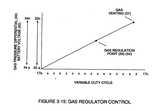
Figure (3-14)
Gas Volume Control
Also written WFC Voltage Ignition Wire
How it is written
- (3-14) 6×
Drawings 4
-
Captioned as this figure · Analog Voltage generator (40)
-
Captioned as this figure · WFC 422DA - Illustrations
-
3-14 WFC Voltage Ignition Wire · Voltage Intensifier Coil Assembly
-
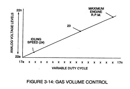
Figure (3-15) · Voltage Amplitude Control Circuit (50)
On this figure 5
- 19 Pulse-Train Signal
- 22 Compounding Action
- 23 Analog Voltage Level Output
- 24 Low
- 35 Resonant Cavity Zone
Where it is named · 6
Analog Voltage generator (40) 5×
-
The newly formed analog signal (22) of Figure (3-14) is a voltage level signal that varies continuously in both time and amplitude to produce a voltage level which is directly proportional to the physical change in pulse train (100 xxx 16n) of Figure (3-13).
-
Figure (3-14)
-
The resultant and varied voltage level (22a xx) varies smoothly over a continuous range of voltage valves (22a xxx 22n) rather than in discrete steps, as illustrated in linear graph (23) of Figure (3-14).
-
Analog circuit (40) also calibrates both engine idling speed (22ax) and maximum engine R.P.M. (22a xxx 22n) by adjusting and maintaining a predetermined or given low (24) and high voltage levels respectively, as further illustrated in Figure (3-14).
Voltage Amplitude Control Circuit (50) 1×
-
Regulator stage (27) of circuit (50) converts battery voltage potential (29) of Figure (3-6) via electrical terminal (31) of Figure (3-5) as to Figure (3-6) into a analog voltage signal (32) of Figure (3-15) which corresponds to but is electrically isolated (crossover voltage from two separate power supplies) from incoming gas volume signal (23) of Figure (3-14), as shown in Figure (35).