(27)
Regulatory Stage
Also written Regulator stage
Where it is first named
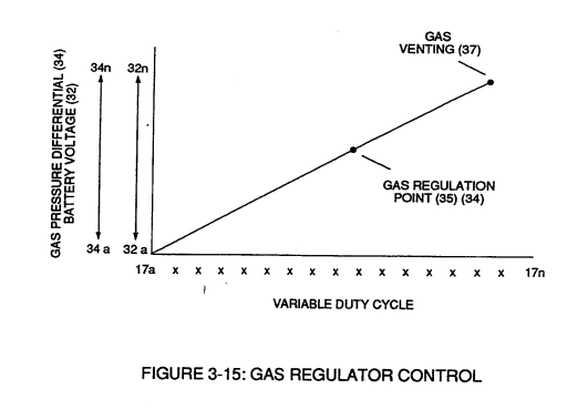
Each regulatory stage (27) and (28) works separately and independent of each other but are! electronically linked or coupled together to produce a common analog signal (32) having a predetermined voltage level (32a xxx), as further shown in Figure (3-15).
How it is written
- (27) 2×
Drawings 17
-
Stanley A. Meyer Page27 of 28 · WFC 417 — WFC 417
-
Figure (3-27) · Voltage Intensifier Circuit (60)
-
Carries this number · Electrically Charged Water Molecule
-
Carries this number · WFC 422DA - Illustrations
-
Carries this number · Electronic Circuit Design
-
Figure (29) · Water Fuel Injector (Taper Resonant Cavity Chamber)
-
2-3 Water Inlet Housing · Water Fuel Injector Illustrations
-
(210) of Figure (3-27) (Memo WFC 422DA) · Covalent Switch-Off
-
(210) of Figure (3-27) · Inductance (FL)
-
Carries this number · Transformer Action
-
(210) of Figure (3-27) · Electrovalent Bonding
-
Carries this number · Wobbling Effect
-
Figure (3-6) · Voltage Amplitude Control Circuit (50)
-
Figure (3-6) · Cell Driver Circuit (90)
-
The figure it sits on · WFC 422DA - Illustrations
-
3-6 Pulsing Core · Voltage Intensifier Coil Assembly
-
Figure (3-6) · Water Fuel Injection System - Page 1
Where it is named · 2
Voltage Amplitude Control Circuit (50) 2×
-
regulatory stage (27)
Each regulatory stage (27) and (28) works separately and independent of each other but are! electronically linked or coupled together to produce a common analog signal (32) having a predetermined voltage level (32a xxx), as further shown in Figure (3-15).
-
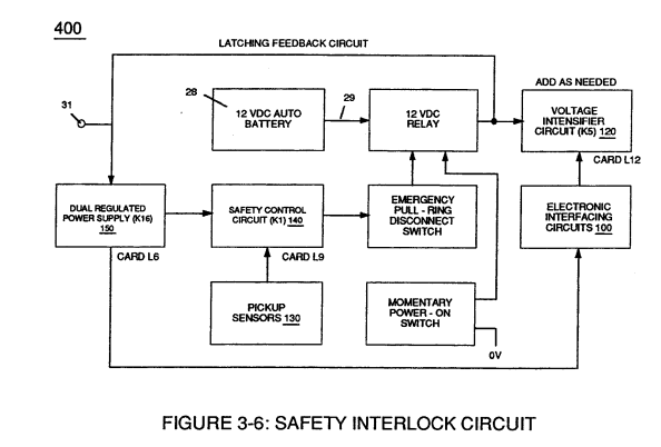
Regulator stage (27)
Regulator stage (27) of circuit (50) converts battery voltage potential (29) of Figure (3-6) via electrical terminal (31) of Figure (3-5) as to Figure (3-6) into a analog voltage signal (32) of Figure (3-15) which corresponds to but is electrically isolated (crossover voltage from two separate power supplies) from incoming gas volume signal (23) of Figure (3-14), as shown in Figure (35).