patent · US10746094B2
Onboard HHO gas generation system for heavy duty trucks
18 August 2020
Page 1 — bibliographic record
( 12 ) Johnson
Unitedet States Patent (10) Patent No .: US 10,746,094 B2 al . (45) Date of Patent : Aug. 18 , 2020 ( 54 ) ONBOARD HHO GAS GENERATION (2013.01 ) ; F02B 43700 (2013.01 ) ; F02B 43/12 SYSTEM FOR HEAVY DUTY TRUCKS (2013.01 ) ; F02B 51/00 (2013.01 ) ; F02B 75/02
( 71 ) Applicant: HyTech Power, LLC , Redmond, WA 19/0671 ( 2013.01 ) ; F02D 19/08 ( 2013.01 ) ; (US ) F02D 19/081 ( 2013.01 ) ; ( 72 ) Inventors : Evan Charles Johnson , Lake Stevens, ( Continued ) WA (US ) ; William A. Woods , ( 58 ) Field of Classification Search
Redmond, WA (US ) CPC . F02B 43/10 ; F02B 43/12 ; C25B 1/04 ; C25B
( 73 ) Assignee : HyTech Power, LLC , Redmond, WA 21/0278 ; FO2M 25/12 ; C01B 3/382 ; (US ) FO2D 41/0027
( * ) Notice: Subject to any disclaimer, the term of this See application file for complete search history. patent is extended or adjusted under 35 References Cited
U.S.C. 154 ( b ) by 0 days. ( 56 )
(22 ) Filed : Aug. 10, 2018 3,310,483 A 3/1967 Rhodes
(Continued )
US 2019/0234297 A1 Aug. 1 , 2019 FOREIGN PATENT DOCUMENTS
Related U.S. Application Data CN 104819075 8/2015 ( 63 ) Continuation of application No. 16/ 056,062 , filed on ( Continued )
(Continued ) OTHER PUBLICATIONS ( 51 ) Int . Ci . International Search Report dated Mar. 6 , 2017 for PCT /US2017 / F02B 43/10 ( 2006.01 ) 020996 .
FO2M 21/02 ( 2006.01 ) (Continued )
(Continued ) Primary Examiner Mark A Laurenzi ( 52 ) U.S. Cl . Assistant Examiner Loren C Edwards
( 2013.01 ) ; C25B 1/04 (2013.01 ) ; C25B 1/06 ( 74 ) Attorney, Agent, or Firm Jones Day ( 2013.01 ) ; C25B 1/12 (2013.01 ) ; C25B 9/06 ( 57 ) ABSTRACT
(2013.01 ) ; FOIN 37023 ( 2013.01 ) ; FOIN A dual - chamber onboard electrolysis system is configured to 3/0205 ( 2013.01 ) ; FOIN 37025 ( 2013.01 ) ; produce HHO gas for heavy duty trucking applications.
( 2013.01 ) ; F01N 3/035 (2013.01 ) ; FO1P 3/20 28 Claims , 11 Drawing Sheets
Page 2
Related U.S. Application Data 4,302,320 A 11/1981 Lewis
( 60 ) Provisional application No. 62/ 623,302 , filed on Jan. 4,761,958 A 8/1988 Hellat 29 , 2018 . 4,773,981 A 9/1988 Bidwell
(51 ) Int. Ci. 5,119,768 A 6/1992 Russell C25B 1/04 ( 2006.01 ) 5,143,025 A 9/1992 Munday
FO1P 3/20 ( 2006.01 ) 5,272,871 A 12/1993 Oshima et al . FOIN 3/025 ( 2006.01 ) 5,293,857 A 3/1994 Meyer FOIN 3/02 ( 2006.01 ) 5,305,715 A 4/1994 Nissley FO2D 19/06 ( 2006.01 ) 5,452,688 A 9/1995 Rose FO2D 41/00 5,458,095 A 10/1995 Post et al . ( 2006.01 ) 5,484,512 A 1/1996 Sasaki et al .
FO2D 19/08 ( 2006.01 ) 5,634,341 A 6/1997 Hughes et al . C25B 9/06 ( 2006.01 ) 5,858,185 A 1/1999 Christian C25B 15/08 (2006.01 ) 6,311,648 B1 11/2001 Larocque FOIN 3/029 ( 2006.01 ) 6,332,434 B1 12/2001 De et al . FO2M 25/12 6,606,856 B1 8/2003 Langer et al . ( 2006.01 ) 6,725,653 B2 4/2004 Tadrous et al .
F02D 41/34 ( 2006.01 ) 6,742,507 B2 6/2004 Keefer et al . F02B 43/12 ( 2006.01 ) 6,833,206 B2 12/2004 Richters et al . FO2B 75/02 ( 2006.01 ) 6,895,945 B2 5/2005 Parsa C25B 1/12 ( 2006.01 ) 6,955,052 B2 10/2005 Primlani FOIN 3/035 ( 2006.01 ) 7,100,542 B2 9/2006 Ehresman
B01D 46/00 ( 2006.01 ) 123 /90.15 C25B 1/06 ( 2006.01 ) 7,258,779 B2 8/2007 Casey et al . C25B 15/02 ( 2006.01 ) 7,273,044 B2 9/2007 Flessner et al . FO2B 43/00 ( 2006.01 ) 7,290,504 B2 11/2007 Lange et al .
FOIN 3/023 ( 2006.01 ) 7,401,578 B2 7/2008 Lindsey et al . FO2B 51/00 ( 2006.01 ) 7,430,991 B2 10/2008 Vanhoose et al . FO2D 41/14 ( 2006.01) 7,475,656 B2 1/2009 Yatsenko ( 52 ) U.S. CI . 7,585,338 B2 9/2009 Yoshizaki CPC F02D 41/0025 ( 2013.01 ) ; FO2D 41/0027 7,621,260 B2 11/2009 Mitani et al .
(2013.01 ) ; F02D 41/345 ( 2013.01 ) ; F02M 7,789,047 B2 9/2010 Shinagawa et al . 21/0206 (2013.01 ) ; FO2M 21/0221 ( 2013.01 ) ; 7,861,696 B2 1/2011 Lund FO2M 21/0239 ( 2013.01 ) ; F02M 21/0248 8,118,012 B2 2/2012 Shinagawa et al . (2013.01 ) ; FO2M 21/0278 ( 2013.01 ) ; F02M 8,127,750 B2 3/2012 Dica et al .
25/12 ( 2013.01 ) ; B01D 2279/30 ( 2013.01 ) ; 8,161,748 B2 4/2012 Haase FOIN 2240/14 ( 2013.01 ) ; FOIN 2240/34 8,168,047 B1 5/2012 Smith (2013.01 ) ; FOIN 2250/02 (2013.01 ) ; F02B 8,186,315 B2
2043/106 (2013.01 ) ; FO2B 2075/027 8,303,798 B2 11/2012 Dees et al . (2013.01 ) ; FO2D 41/009 (2013.01 ) ; FO2D 8,449,733 B2 5/2013 Owens 41/1446 ( 2013.01 ) ; FO2D 41/1498 ( 2013.01 ) ; 8,449,737 B2 5/2013 Richardson F02D 2200/021 (2013.01 ) ; F02D 2200/0404 8,464,667 B1 6/2013 Stama (2013.01 ) ; FO2D 2200/0406 (2013.01 ) ; F02D 8,544,452 B1
2200/0602 (2013.01 ) ; F02D 2200/0606 8,714,115 B2 5/2014 Mcconahay et al . (2013.01 ) ; F02D 2200/0625 (2013.01 ) ; F02D 8,720,390 B2 5/2014 Lee 2200/101 (2013.01 ) ; FO2D 2200/1002 8,808,528 B2 8/2014 Richardson
( 56 ) References Cited 8,912,748 B2 12/2014 Hiebl et al .
3,679,568 A 7/1972 Westerlund 9,051,872 B2 6/2015 Monros 3,799,124 A 3/1974 Swain 9,140,181 B2 9/2015 Turgeon et al . 3,854,494 A 12/1974 Zahorsky 9,157,159 B2 10/2015 Hansen 3,999,379 A 12/1976 LeFebvre 9,194,583 B2 11/2015 De la Sovera 4,003,345 A 1/1977 Bradley 9,212,634 B2 12/2015 Adair 4,004,554 A 1/1977 Kosaka et al . 9,249,369 B2 2/2016 Wey 4,014,777 A 3/1977 Brown 9,267,428 B2 2/2016 Riesselman et al . 4,023,545 A 5/1977 Mosher et al . 9,291,129 B2 3/2016 Robinson 4,028,213 A 6/1977 Ford 9,340,881 B2 5/2016 Packer 4,031,865 A 6/1977 Dufour 9,353,451 B2 5/2016 Haywood 4,033,133 A 7/1977 Houseman et al. 9,388,749 B2 7/2016 MacDonald 4,111,160 A 9/1978 Talenti 9,404,449 B2 8/2016 Licitar 4,140,090 A 2/1979 Lindberg 9,440,851 B2 9/2016 Hwang 4,203,818 A 5/1980 Greaves 9,464,553 B2 10/2016 Wold 4,209,303 A 6/1980 Ricks 9,499,452 B2 11/2016 Courtright 4,271,793 A 6/1981 Valdespino C25B 9/06 9,562,295 B2 2/2017 McDugle
Page 3
( 56 ) References Cited 2012/0186991 Al
7/2012 Gootblatt
2012/0234265 A1 * 9/2012 Ball C25B 1/08 9,695,757 B2 7/2017 Mcmahon 123/3 9,733,155 B2 8/2017 Monros 2012/0282534 A1 11/2012 Braun et al . 9,771,658 B2 9/2017 Haring 2012/0298054 A1 * 11/2012 Dinsmore FO2B 43/10 9,863,309 B2 1/2018 Salter 123/3 9,920,714 B2 3/2018 Kim et al . 2013/0037003 A1 2/2013 Sheerin 2001/0003276 A1 6/2001 De Souza et al . 2013/0061822 A1 3/2013 Adair 2003/0159663 Al 8/2003 Zagaja et al . 2013/0125454 Al 5/2013 Lewis et al. 2003/0183179 Al 10/2003 Lin 2013/0133595 Al 5/2013 Chen 2003/0205482 A1 11/2003 Allen 2013/0174930 A1 7/2013 Arroyo et al . 2004/0040838 A1 3/2004 Helmke et al . 2013/0247867 Al 9/2013 Shmueli et al . 2004/0101795 Al 5/2004 Fairfull 2013/0312384 A1 * 11/2013 Hwang CO1B 3/382 2004/0131902 Al 7/2004 Frank et al . 60 /39.12 2004/0149591 A1 8/2004 Klein et al . 2013/0327286 A1 12/2013 Ito 2005/0217991 A1 10/2005 Dahlquist 2014/0014049 Al 1/2014 Watson et al . 2005/0229872 A1 10/2005 Lange 2014/0090986 Al 4/2014 Bethurem 2006/0081290 A1 4/2006 Sachs 2014/0096727 Al 4/2014 Ortenheim et al . 2006/0179819 Al 8/2006 Sullivan 2014/0096728 Al 4/2014 Ortenheim et al . 2007/0080071 A1 4/2007 Perry 2014/0202877 A1 7/2014 Greenbaum 2007/0215070 Al 9/2007 Yatsenko 2014/0245974 Al 9/2014 Elsarrag et al . 2007/0246351 A1 10/2007 Smola et al . 2014/0261253 Al 9/2014 Wold 2008/0006743 A1 1/2008 Miller et al . 2014/0262757 Al 9/2014 Forbes 2008/0022982 Al 1/2008 Kamiyama 2014/0379237 A1 12/2014 Rodriguez 2008/0038478 Al 2/2008 Klein 2015/0040843 A1 2/2015 Goldman et al . 2008/0047830 A1 2/2008 Fairfull et al . 2015/0040844 A1 2/2015 Goldman et al . 2008/0110421 A1 5/2008 Flessner et al . 2015/0101926 A1 4/2015 Burns 2009/0194421 A1 8/2009 Sato et al . 2015/0122237 Al 5/2015 Kato 2009/0199465 A1 8/2009 Klein et al . 2015/0167180 A1 6/2015 Maddox 2009/0283402 A1 11/2009 Osman 2015/0226113 Al 8/2015 Alexander et al . 2009/0283420 A1 11/2009 Schadeck et al. 2015/0292380 A1 10/2015 Ballinger et al . 2010/0032221 A1 2/2010 Storey 2016/0047284 A1 2/2016 Turgeon et al . 2010/0038236 A1 2/2010 Rivera 2016/0084157 A1 3/2016 Hudson 2010/0038257 A1 * 2/2010 Sohn C25B 1/04 2016/0131024 A1 5/2016 Tsurumi
2010/0049417 Al 2/2010 Bailey et al . 2016/0153355 Al 6/2016 Wylie et al . 2010/0077756 A1 4/2010 Poyyapakkam et al. 2016/0333487 A1 11/2016 Delgado et al . 2010/0132634 Al 6/2010 Selano 2017/0037815 Al 2/2017 Lowe et al . 2010/0132661 Al 6/2010 Klein et al . 2017/0159618 A1 6/2017 Forbes et al. 2010/0139597 A1 6/2010 Wisdom et al. 2017/0211192 Al 7/2017 Bozhilov et al . 2010/0147231 A1 6/2010 Bogers et al. 2017/0211516 Al 7/2017 Monros 2010/0147232 Al 6/2010 Heath et al. 2017/0254259 Al 9/2017 Johnson et al . 2010/0155233 A1 6/2010 Hwang 2017/0260633 A1 9/2017 Gui 2010/0206721 A1 8/2010 Snidvongs 2018/0038318 Al 2/2018 Ross 2010/0229839 A1 9/2010 Fornarelli 2018/0058387 A1 3/2018 De Meneses et al . 2010/0252421 A1 10/2010 Yang 2018/0087464 Al 3/2018 Sekita 2010/0263379 Al 10/2010 Berkyto 2018/0112608 Al 4/2018 Bridge et al . 2010/0275859 Al 11/2010 Klotz 2018/0298813 A1 10/2018 Manthei et al . 2010/0300381 A1 12/2010 Harper 2018/0328297 Al 11/2018 Ueno et al .
2011/0005939 A1 1/2011 Haywood FOREIGN PATENT DOCUMENTS
2011/0061957 A1 3/2011 Hargett GB 2539904 4/2017 2011/0067652 A1 3/2011 Bishop GB 2539905 4/2017 2011/0089029 A1 4/2011 Volk, Jr. GB 2539906 4/2017 2011/0100803 Al 5/2011 Dee et al . JP 2001-003818 1/2001
2011/0174242 A1 * 7/2011 McConahay C25B 9/063 KR 2010-0105108 9/2010
2011/0174277 A1 7/2011 Socolove WO WO 2006/037006 4/2006
2011/0191008 Al 8/2011 Mcconahay et al . OTHER PUBLICATIONS
2011/0207007 A1 8/2011 Ab et al . Written Opinion of the International Search Authority dated Jul. 14 ,
2011/0220039 Al 9/2011 Nowicki et al . 2017 for PCT/US2017 /020996 .
2011/0253070 A1 10/2011 Haring Office Action dated Oct. 29 , 2018 in U.S. Appl. No. 16 / 101,178 . 2011/0274615 Al 11/2011 Ishikawa Office Action dated Oct. 30 , 2018 in U.S. Appl. No. 15 /451,266 . 2011/0303194 A1 12/2011 Fong et al. Non -Final Office Action in U.S. Appl. No. 16/ 101,207 dated Nov. 2012/0037510 Al 2/2012 Bethurem 30, 2018 .
2012/0067304 A1 3/2012 Littmann Non - Final Office Action in U.S. Appl. No. 16/ 101,223 dated Nov.
2012/0111290 Al 5/2012 McBride et al . 29, 2018 2012/0111734 A1 5/2012 Kramer Office Action in Korean Patent Appln . No. 2014-7027476 dated 2012/0118727 A1 5/2012 McDugle Nov. 19 , 2018 .
2012/0144982 Al 6/2012 Ohlson Final Office Action in U.S. Appl. No. 16/ 101,178 dated Jan. 25 , 2012/0181168 A1 7/2012 Gargiuolo et al. 2019 .
Page 4
OTHER PUBLICATIONS
Non - Final Office Action in U.S. Appl. No. 16/ 101,084 dated Jan. 30 ,
Non - Final Office Action in U.S. Appl. No. 16 / 101,137 dated Feb.
* cited by examiner

Page 5
Drawing sheet — no readable text.

Page 6
Drawing sheet — no readable text.
Page 7
Drawing sheet — no readable text.
Page 8
Drawing sheet — no readable text.
Page 9
Drawing sheet — no readable text.
Page 10
Drawing sheet — no readable text.
Page 11
Drawing sheet — no readable text.
Page 12
Drawing sheet — no readable text.
Page 13
Drawing sheet — no readable text.
Page 14
Drawing sheet — no readable text.
Page 15
Drawing sheet — no readable text.
Page 16
ONBOARD HHO GAS GENERATION engine. In certain embodiments , for example, the method SYSTEM FOR HEAVY DUTY TRUCKS may comprise introducing in the range of 1.25-30 liters ( for example in the range of 2-5 liters ) of HHO gas per hour per
CROSS - REFERENCE TO RELATED liter of displacement of the internal combustion engine. In APPLICATIONS 5 certain embodiments, for example , the method may com
This application is a continuation of U.S. application Ser. prise combusting a quantity of carbonaceous fuel in the No. 16 / 056,062 , filed Aug. 6 , 2018 , which claims the benefit presence of the introduced HHO gas to increase fuel of U.S. Provisional Application No. 62 / 623,302 , filed Jan. economy of the carbonaceous fuel by at least 5 % ( for 29 , 2018. The foregoing related applications , in their 10 example at least 10 % or at least 20% ) . entirety, are incorporated herein by reference . In certain embodiments, for example, the method may further comprise electrolyzing an aqueous electrolyte solu
INCORPORATION BY REFERENCE tion at an average ( or maximum ) current draw of less than 20 amps ( for example less than 15 amps or in the range of
lished Aug. 29 , 2013 , U.S. Pat. No. 9,267,428 , granted Feb. 15 10-15 amps) to formrange of 9-12 amps, or in the range of 9-15 amps, in the 23 , 2016 , U.S. Patent Application Publ . No. 2016/0138496 , for example , the aqueous the HHO gas . In certain embodiments , published May 19 , 2016 , and U.S. Patent Application Publ . no more than 3 wt . % of any electrolyte solution may comprise No. 2017/0254259 , published Sep. 7 , 2017 , (hereinafter salt ( for example no more than referred to as the “ REFERENCE APPLICATIONS”) are 3 wt . % potassium carbonate such as in the range of 1.5-3 wt . hereby incorporated by reference in their entirety. 20 % potassium carbonate ). In certain embodiments, for example, the electrolyzing may be performed with a total
FIELD OF THE INVENTION electrical resistance of less than 20 ohm (for example less than 10 ohm or less than 3 ohm ). In certain embodiments , for
This disclosure relates to systems and methods for a example, the internal combustion engine may power a dual- chamber onboard electrolysis system producing HHO 25 vehicle. In certain embodiments, for example, the electro gas for heavy duty trucking applications. lyzing may occur onboard the vehicle. In certain embodi BACKGROUND OF THE INVENTION ments, for example, the electrolyzing may consume elec trolysis of up to 20 ounces ( for example in the range of 4-10
Worldwide emissions, stemming primarily from the burn ounces or up to 4-10 ounces) of the aqueous electrolyte per ing of fossil fuels, are reaching the highest levels ever 30 liter displacement of the internal combustion engine per recorded . By some measures , the emissions associated with 10,000 miles traveling distance of the vehicle . In certain burning fossil fuels have already reached nearly 5 metric embodiments, for example, the vehicle may be a class 8 tons /person /year. Internal combustion engines , including truck .
diesel engines , are a major contributor of fossil fuel emis In certain embodiments, for example , the internal com sions . In fact, by some measures, there are over 300 million 35 bustion engine may be a gasoline engine. In certain embodi diesel engines worldwide. ments, for example, the internal combustion engine may be Internal combustion engines, and diesel engines in par a diesel engine. In certain embodiments, for example , the ticular, emit particulate matter (PM) and governments diesel engine may be a heavy duty diesel engine sized to around the world are realizing that these emissions are a produce in the range of 430-500 hp. In certain embodiments, cause for great concern. As a result, many countries/juris- 40 for example , the internal combustion engine may have a dictions , including the United States , the European Union displacement in the range of 11-16 liters. In certain embodi and China , are passing regulations which require signifi ments, for example, the internal combustion engine may be cantly reduced emissions from internal combustion engines, sized to produce in the range of 200-250 hp . In certain including diesel engines. embodiments, for example, the internal combustion engine Accordingly, more and more , businesses are forced to 45 may comply with these new air quality standards at their own certainhave a displacement in the range of 6-11 liters . In embodiments , for example, the internal combustion expense . Sometimes , the costs for modifying a large internal engine may be a generator set engine. In certain embodi combustion engine installation to meet new regulations can ments, for example, the generator set engine may have a exceed US $ 30,000 per engine.
An attributable amount of emissions created by internal displacement in the range of 6-60 liters. In certain embodi combustion engines is a result of the internal combustion 50 ments, for example, the generator set engine may have a engines failure to convert all of the energy available in the displacement in the range of 2-6 liters per cylinder. In certain hydrocarbon fuel ( e.g. , gasoline and / or diesel fuel ). This embodiments , for example, the generator set engine may be incomplete conversion is often a result of what is commonly sized to produce more than 1000 hp. In certain embodi referred to as incomplete combustion of the fuel. Incomplete ments, for example, the generator set engine may be sized to combustion results in an unnecessary loss of fuel efficiency 55 produce 1000-2000 hp. In certain embodiments , for and an increase in pollution . example, the internal combustion engine may be a biofuel Accordingly, it is desirable to have a system and / or engine.
method for use with an internal combustion engine that aids In certain embodiments, for example , the introducing may in achieving more complete combustion of the hydrocarbon comprise depositing air - free portions of the HHO gas ( for fuel, reduced emissions , and / or better fuel economy, or 60 example portions of the HHO gas comprising less than 5 wt . otherwise improves certain metrics of the internal combus % air, less than 1 wt . % air, less than 1000 ppm air, less than tion engine. 500 ppmair , less than 250 ppm air ,or less than 100 ppm air) into an air stream supply for a particular combustion cham
BRIEF SUMMARY OF THE INVENTION ber, within 3 inches ( for example within 1 % inches or within 65 1 inch) of at least one combustion chamber inlet orifice ( for
Certain embodiments may provide, for example, a method example an air intake orifice) of the internal combustion for increasing fuel economy of an internal combustion engine.
Page 17
In certain embodiments, for example, the method may the internal combustion engine, or during the first 180 reduce one or more engine -out emissions ( for example a seconds of starting the internal combustion engine ). In nitrogen oxide (NOx ) emission ) by at least 10 % . The certain embodiments, for example, the combusting may improvement in reduced emissions may be relative to an achieve at least 97 % complete combustion of the quantity of internal combustion engine running under identical or sub- 5 carbonaceous fuel.
stantially identical conditions ( for example, taking into Certain embodiments may provide, for example , a method account engine load , average engine load , run - time, average for increasing fuel economy of an internal combustion run - time, temperature, average temperature , speed, average engine. In certain embodiments , for example, the method speed, rpm's, average rpm's, acceleration , average accelera may comprise introducing in the range of 2-5 liters of HHO tion and / or type of primary fuel) without HHO gas . 10 gas per hour per liter of displacement of the internal com In certain embodiments, for example, the introduced bustion engine. In certain embodiments, for example, the HHO gas may be no more than 500 ppm ( for example in the introducing may comprise depositing a first portion of the range of 1-500 ppm , no more than 250 ppm , in the range of HHO gas in a first air stream within 3 inches of first 1-250 ppm , in the range of 1-100 ppm , in the range of combustion chamber inlet orifice of the internal combustion 25-100 ppm , or in the range of 50-100 ppm) relative to the 15 engine. In certain embodiments, for example, the introduc weight of the combusted quantity of carbonaceous fuel. ing may comprise depositing a second portion of the HHO In certain embodiments, for example, the method may gas in a second air stream within 3 inches of a second reduce exhaust temperature by at least 10 ° F. ( for example combustion chamber inlet orifice of the internal combustion at least 20 ° F. or at least 30 ° F. ) . engine. In certain embodiments , for example, the introduc In certain embodiments, for example, the HHO gas may 20 ing may comprise depositing at least a third portion of the be substantially hydrogen . HHO gas in at least a third air stream within 3 inches of at In certain embodiments, for example, the method may least a third combustion chamber inlet orifice of the internal further comprise delivering HHO gas to a diesel particulate combustion engine. In certain embodiments , for example, filter (DPF) regenerator system . the method may comprise combusting a quantity of carbo In certain embodiments, for example, at least a portion of 25 naceous fuel in the presence of at least one of the deposited the in the range of 1.25-30 liters of the HHO gas stream per first portion of the HHO gas , the deposited second portion of hour per liter of displacement of the internal combustion the HHO gas , and the deposited at least a third portion of the engine may be passed through a heat exchanger prior to the HHO gas to increase fuel economy of the carbonaceous fuel introducing. In certain embodiments, for example, the heat by at least 5 % .
exchanger may receive an engine exhaust stream . In certain 30 Certain embodiments may provide, for example, a method embodiments, for example, the engine exhaust stream may for increasing fuel economy of an internal combustion be used in the heat exchanger to heat the HHO gas stream . engine during cold start to achieve at least 85 % ( for example In certain embodiments, for example, the heat exchanger at least 90 % , at least 93 % , at least 5 % , at least 97 % , least may receive an engine coolant stream . In certain embodi 99 % , at least 99.5 % , or at least 99.9 % ) complete combustion ments, for example, the engine coolant stream may be used 35 of the quantity of carbonaceous fuel during the first 60 in the heat exchanger to adjust the temperature ( for example, seconds (or 120 seconds or 180 seconds ) of starting the cooling and/ or heating) of the HHO gas stream . internal combustion engine . In certain embodiments, for In certain embodiments, for example, a portion of the example , the method may comprise combusting a first introduced HHO gas may be introduced to a first combustion quantity of carbonaceous fuel in a first combustion chamber chamber of the internal combustion engine during a portion 40 of the internal combustion engine in the presence of no more of an intake stroke of a combustion cylinder, the combustion than 500 ppm ( for example in the range of 1-500 ppm , no cylinder comprising the combustion chamber. In certain more than 250 ppm , in the range of 1-250 ppm , in the range embodiments, for example, the portion of an intake stroke of 1-100 ppm , in the range of 25-100 ppm , or in the range may be less than 50 % of the intake stroke . In certain of 50-100 ppm) HHO gas , relative to the quantity of embodiments, for example, the during a portion of an intake 45 carbonaceous fuel. In certain embodiments, for example, the stroke is when the intake stroke may be at an angle in the method may comprise combusting a second quantity of the range of 0-40 ° from top - dead - center. carbonaceous fuel in a second combustion chamber of the Certain embodiments may provide, for example, a method internal combustion engine in the presence of no more than for increasing fuel economy of an internal combustion 500 ppm ( for example in the range of 1-500 ppm , no more engine ( for example by at least 3 % , at least 4 % , at least 5 % , 50 than 250 ppm, in the range of 1-250 ppm, in the range of of at least 6 % , at least 8 % , or by at least 10% ) . The improve 1-100 ppm , in the range of 25-100 ppm , or in the range ment in fuel economy may be relative to the internal 50-100 ppm) HHO gas , relative to the quantity of carbona combustion engine running under identical or substantially ceous fuel. In certain embodiments, for example , the method identical conditions ( for example, taking into account engine may comprise combusting at least a third quantity of car load, average engine load, run -time, average run - time, tem- 55 bonaceous fuel in at least a third combustion chamber of the perature, average temperature, speed , average speed, rpm's , internal combustion engine in the presence of no more than average rpm's, acceleration , average acceleration and / or 500 ppm ( for example in the range of 1-500 ppm , no more type of primary fuel) without HHO gas . In certain embodi than 250 ppm , in the range of 1-250 ppm , in the range of ments , for example, the method may comprise combusting 1-100 ppm , in the range of 25-100 ppm , or in the range of a quantity of carbonaceous fuel in at least one combustion 60 50-100 ppm) HHO gas , relative to the quantity of carbona chamber of the internal combustion engine in the presence ceous fuel.
of no more than 500 ppm ( for example in the range of 1-500 Certain embodiments may provide, for example , a method ppm , no more than 250 ppm , in the range of 1-250 ppm , in for increasing fuel economy of an internal combustion the range of 1-100 ppm , in the range of 25-100 ppm , or in engine during cold start to achieve at least 85 % ( for example the range of 50-100 ppm) HHO gas during cold start ( for 65 at least 90 % , at least 93 % , at least 95 % , at least 97 % , at least example during the first 60 seconds of starting the internal 99 % , at least 99.5 % , or at least 99.9 % ) complete combustion combustion engine, during the first 120 seconds of starting of the quantity of carbonaceous fuel before the internal
Page 18
combustion engine reaches 50 % of a steady state operating second combustion chamber inlet orifice of the internal temperature of the internal combustion engine after starting combustion engine; and c ) depositing at least a third portion the internal combustion engine. The improvement in fuel of the HHO gas in at least a third air stream within 3 inches economy may be relative to the internal combustion engine of at least a third combustion chamber inlet orifice of the running under identical or substantially identical conditions 5 internal combustion engine; and ii ) combusting a quantity of ( for example, taking into account engine load, average carbonaceous fuel in the presence of the introduced HHO engine load , run - time, average run -time, temperature , aver gas to increase fuel economy of the carbonaceous fuel by at age temperature, speed , average speed, rpm's, average least 5 % . The improvement in fuel economy may be relative rpm's, acceleration , average acceleration and / or type of to the internal combustion engine running under identical or primary fuel) without HHO gas . In certain embodiments, for 10 substantially identical conditions ( for example, taking into example , the method may comprise combusting a first account engine load , average engine load , run - time, average quantity of carbonaceous fuel in a first combustion chamber run - time, temperature, average temperature , speed, average of the internal combustion engine in the presence of no more speed , rpm's, average rpm's, acceleration , average accelera than 500 ppm ( for example in the range of 1-500 ppm , no tion and /or type of primary fuel) without HHO gas . more than 250 ppm , in the range of 1-250 ppm , in the range 15 Certain embodiments may provide, for example , a method of 1-100 ppm , in the range of 25-100 ppm , or in the range for increasing fuel economy of an internal combustion of 50-100 ppm) HHO gas , relative to the quantity of engine during cold start to achieve at least 97 % complete carbonaceous fuel. In certain embodiments, for example , the combustion of the quantity of carbonaceous fuel during the method may comprise combusting a second quantity of the first 60 seconds ( or 120 seconds or 180 seconds ) of starting carbonaceous fuel in a second combustion chamber of the 20 the internal combustion engine, comprising: i ) combusting a internal combustion engine in the presence of no more than first quantity of carbonaceous fuel in a first combustion 500 ppm ( for example in the range of 1-500 ppm , no more chamber of the internal combustion engine in the presence than 250 ppm , in the range of 1-250 ppm , in the range of of less than 500 ppm HHO gas , relative to the quantity of 1-100 ppm , in the range of 25-100 ppm , or in the range of carbonaceous fuel; ii ) combusting a second quantity of the 50-100 ppm) HHO gas , relative to the quantity of carbona- 25 carbonaceous fuel in a second combustion chamber of the ceous fuel. In certain embodiments, for example , the method internal combustion engine in the presence of less than 500 may comprise combusting at least a third quantity of car ppm HHO gas , relative to the quantity of carbonaceous fuel; bonaceous fuel in at least a third combustion chamber of the and iii ) combusting at least a third quantity of carbonaceous internal combustion engine in the presence of no more than fuel in at least a third combustion chamber of the internal 500 ppm ( for example in the range of 1-500 ppm , no more 30 combustion engine in the presence of less than 500 ppm than 250 ppm , in the range of 1-250 ppm , in the range of HHO gas , relative to the quantity of carbonaceous fuel. The 1-100 ppm , in the range of 25-100 ppm , or in the range of improvement in fuel economy may be relative to the internal 50-100 ppm) HHO gas , relative to the quantity of carbona combustion engine running under identical or substantially ceous fuel. identical conditions ( for example, taking into account engine Certain embodiments may provide, for example , a method 35 load, average engine load , run -time, average run -time, tem for increasing fuel economy of an internal combustion perature, average temperature, speed, average speed, rpm's, engine, comprising: i ) introducing in the range of 2-5 liters average rpm's, acceleration , average acceleration and /or of HHO gas per hour per liter of displacement of the internal type of primary fuel) without HHO gas . combustion engine ; and ii ) combusting a quantity of carbo Certain embodiments may provide, for example, a diesel naceous fuel in the presence of the introduced HHO gas to 40 particulate filter (DPF ) burner configured to combust a fuel increase fuel economy of the carbonaceous fuel by at least to provide a heated gas stream to a DPF system . In certain 5 % . The improvement in fuel economy may be relative to embodiments, for example, the DPF burner may comprise the internal combustion engine running under identical or an HHO gas injector configured to provide a supply of HHO substantially identical conditions ( for example, taking into gas proximate the DPF burner. In certain embodiments, for account engine load , average engine load , run -time, average 45 example, the DPF burner may be retrofitted with an HHO run - time, temperature, average temperature, speed, average gas injector configured to provide a supply of HHO gas speed, rpm's , average rpm's, acceleration , average accelera proximate the DPF burner.
tion and / or type of primary fuel) without HHO gas . Certain Certain embodiments may provide, for example, a diesel embodiments may provide, for example, a method for particulate filter (DPF ) regenerator system . In certain increasing fuel economy of an internal combustion engine, 50 embodiments, for example, the system may comprise a DPF comprising : combusting a quantity of carbonaceous fuel in burner configured to combust a fuel ( for example a petro at least one combustion chamber of the internal combustion leum -based fuel such as gasoline or diesel ). In certain engine in the presence of no more than 500 ppm ( for embodiments, for example , the system may comprise an example in the range of 1-500 ppm , no more than 250 ppm , HHO gas injector configured to provide a supply of HHO in the range of 1-250 ppm , in the range of 1-100 ppm , in the 55 gas proximate the DPF burner . range of 25-100 ppm , or in the range of 50-100 ppm) HHO In certain embodiments, for example, the DPF may be a gas during cold start, relative to the quantity of carbonaceous wall - flow DPF . In certain embodiments, for example , the fuel. DPF may be cooperatively coupled to at least one exhaust Certain embodiments may provide, for example, a method pipe .
for increasing fuel economy of an internal combustion 60 In certain embodiments, for example, the DPF burner may engine , comprising: i ) introducing in the range of 2-5 liters atomize the fuel and aim the atomized fuel in the direction of HHO gas per hour per liter of displacement of the internal of a combustion zone , the combustion zone configured to combustion engine, the introducing comprising: a ) deposit combust the atomized fuel in the presence of the supply of ing a first portion of the HHO gas in a first air stream within HHO gas to form a heated gas stream . In certain embodi 3 inches of a first combustion chamber inlet orifice of the 65 ments, for example, the DPF burner may comprise an internal combustion engine; b ) depositing a second portion evaporation zone and a combustion zone, the evaporation of the HHO gas in a second air stream within 3 inches of a zone configured to atomize the fuel, the combustion zone
Page 19
configured to combust the atomized fuel in the presence of supply at multiple locations about an internal combustion the supply of HHO gas to form a heated gas stream . engine. In certain embodiments, for example, the plurality of In certain embodiments, for example, the system may further HHO gas injectors may comprise : a ) a first injector further comprise a heat transfer element in thermal commu of the plurality of further HHO gas injectors configured to nication with the DPF burner and at least one exhaust pipe 5 deliver a first portion of the further supply of HHO gas to a upstream of the DPF. first location about a first combustion chamber inlet of the In certain embodiments, for example, the fuel may be a internal combustion engine; b ) a second injector of the diesel fuel. plurality of further HHO gas injectors configured to deliver In certain embodiments, for example, the DPF regenerator a second portion of the further supply of HHO gas to a may be adapted for use onboard a vehicle . In certain 10 second location about a second combustion chamber inlet of embodiments , for example , the DPF regenerator may be the internal combustion engine; and c ) at least a third adapted for use with a generator set engine. injector of the plurality of further HHO gas injectors con In certain embodiments, for example, the DPF regenerator figured to deliver at least a third portion of the further supply system may further comprise a lance cooperatively coupled of HHO gas to at least a third location about at least a third to the HHO injector, the lance having an outlet distal from 15 combustion chamber inlet of the internal combustion engine. the injector, the outlet positioned within 3 inches of the DPF In certain embodiments, for example , the first injector burner, for example within 3 inches of the combustion zone may be configured to deliver the first portion of the further of the DPF burner . supply of HHO gas to the first combustion chamber during In certain embodiments, for example, the DPF regenerator a portion of an intake stroke of a combustion cylinder, the system may further comprise an HHO gas supply system or 20 combustion cylinder comprising the first combustion cham be retrofitted to comprise an HHO gas supply system . In ber. In certain embodiments, for example, the portion of an certain embodiments, for example , the HHO gas supply intake stroke may be less than 50% of the intake stroke . In system may comprise an electrolysis unit. In certain embodi certain embodiments, for example, the during a portion of an ments , for example , the electrolysis unit may be adapted for intake stroke is when the intake stroke may be at an angle in use onboard a vehicle . In certain embodiments, for example, 25 the range of 0-40 ° from top -dead - center. the HHO gas supply system may be configured for in situ Certain embodiments may provide, for example, a method generation of the supply of HHO gas . In certain embodi to regenerate a diesel particulate filter ( DPF ) . In certain ments, for example, the DPF regenerator system may be embodiments, for example, the method may comprise com exclusive of a device (for example a scrubber ) for reducing busting a fuel in the presence of an injected quantity of HHO moisture in an HHO gas stream produced by the electrolysis 30 gas to form a heated gas stream . In certain embodiments , for unit . In certain embodiments, for example, the HHO gas example , the method may comprise transferring heat from supply system may be configured to provide moisture - free the heated gas stream directly and/ or indirectly through the HHO gas . In certain embodiments , for example , the HHO DPF .
gas supply system may be configured to provide HHO gas In certain embodiments, for example , the injected quan having no more than 0.062 g /cm3 ( for example no more than 35 tity of HHO gas may be air - free and /or moisture - free prior 0.06 g / cm ", no more than 0.05 g / cm ", or no more than 0.04 to being injected. In certain embodiments, for example, the g /cm ) water. In certain embodiments, for example, the transferring heat may heat the at least one exhaust stream to HHO gas supply system may be configured to provide HHO a temperature above 600 ° C. ( for example to a temperature gas that is at or below a saturation point with water at a above 650 ° C. ) . In certain embodiments, for example, the temperature of no more than 120 ° F. ( for example no more 40 injected quantity of HHO gas may be generated in real time . than 110 ° F. or no more than 100 ° F. ) . Certain embodiments may provide, for example, a diesel In certain embodiments, for example, the DPF regenerator particulate filter (DPF ) regenerator system , comprising: i ) a may be adapted for use with a nonroad engine or non -over DPF burner configured to combust a fuel; and ii ) an HHO the -road engine. In certain embodiments, for example, DPF gas injector configured to provide a controlled supply of regenerator may be adapted for use with an off - road vehicle . 45 HHO gas proximate the DPF burner . In certain embodiments, for example, the DPF regenerator Certain embodiments may provide, for example , a method may be adapted for use with a stationary engine. In certain to regenerate a diesel particulate filter (DPF ) , comprising : i ) embodiments, for example , the DPF regenerator may be combusting a fuel in the presence of an injected quantity of adapted for use with for use with a locomotive engine . In HHO gas to form a heated gas stream ; and ii ) transferring certain embodiments, for example , the DPF regenerator may 50 heat from the heated gas stream directly and / or indirectly to be adapted for use with for use with a marine engine. the DPF .
In certain embodiments, for example, the DPF regenerator Certain embodiments may provide, for example , a system system may further comprise a heat exchanger configured to to provide HHO gas to a diesel engine. In certain embodi receive the controlled supply of HHO gas , the heat ments, for example, the system may comprise a multi -point exchanger disposed upstream of the DPF burner. In certain 55 gas distribution system adapted to receive an HHO gas embodiments, for example, the heat exchanger may be in supply. In certain embodiments, for example, the multi -point thermal communication with an internal combustion engine gas distribution system may comprise a plurality of injectors and / or the DPF regenerator system . In certain embodiments , configured to deliver portions of the received HHO gas for example, the heat exchanger may be configured to supply at multiple locations about a diesel engine. In certain receive an engine exhaust stream . In certain embodiments , 60 embodiments , for example, the multi -point gas distribution for example, the heat exchanger may be configured to system may comprise at least one further injector configured receive an engine coolant stream . In certain embodiments, to deliver a further portion of the received HHO gas supply for example, the heat exchanger may be configured to to a diesel particulate filter (DPF ) regenerator system . receive a DPF regenerator system exhaust stream . In certain embodiments, for example , at least one injector In certain embodiments, for example, the DPF regenerator 65 of the plurality of injectors may be coupled to an HHO gas system may further comprise a plurality of further HHO gas outlet, the at least one injector cooperatively configured with injectors configured to deliver a further supply of HHO gas the diesel engine to be fixedly positioned at a predetermined
Page 20
location about the diesel engine, whereby the HHO gas prise exchanging heat between the first quantity of HHO gas outlet is within 3 inches of at least one combustion chamber and a diesel engine exhaust stream . inlet of the diesel engine. In certain embodiments, for In certain embodiments, for example, the method may example , the at least one injector may be configured to be further comprise generating the first quantity of HHO gas on fixedly positioned at a retrofitted attachment point of the 5 demand .
diesel engine. In certain embodiments, for example, the Certain embodiments may provide, for example , a system combustion chamber inlet may be an air intake orifice . to provide HHO gas to a diesel engine. In certain embodi In certain embodiments, for example, the system to pro ments, for example, the system may comprise a multi -point vide HHO gas to a diesel engine may further comprise a gas distribution system for controlled delivery of an HHO control system , the control system configured to control 10 gas supply. In certain embodiments, for example, the multi timing and / or duration for the delivering a portion of HHO point gas distribution system may comprise a plurality of gas and for the delivering a further portion of HHO gas . In injectors configured to deliver portions of the HHO gas certain embodiments, for example, the timing and duration supply at multiple locations about a diesel engine. In certain of the further delivering may be different from the timing embodiments, for example, the multi-point gas distribution and / or duration of the delivering. In certain embodiments, 15 system may comprise a first injector of the plurality of for example , the control system may be configured to injectors configured to deliver a first portion of HHO gas of process intake stroke timing data for at least one air intake the portions of the HHO gas supply to a first location about orifice of the diesel engine. a first combustion chamber inlet of the diesel engine. In In certain embodiments, for example, the control system certain embodiments, for example , the multi -point gas dis for providing HHO gas to a diesel engine may be adapted to 20 tribution system may comprise a second injector of the provide HHO gas to a diesel engine coupled to a vehicle. In plurality of injectors configured to deliver a second portion certain embodiments, for example, the control system to of HHO gas of the portions of the HHO gas supply to a provide HHO gas to a diesel engine may be adapted to second location about a second combustion chamber inlet of connect to an HHO gas supply system . In certain embodi the diesel engine. In certain embodiments, for example, the ments , for example, the control system may be adapted to 25 multi -point gas distribution system may comprise at least a connect to a multi- point gas distribution system adapted to third injector of the plurality of injectors configured to connect to an HHO gas supply system . In certain embodi deliver at least a third portion of HHO gas of the portions of ments, for example, the multi -point gas distribution system the HHO gas supply to at least a third location about at least may be adapted to connect to an outlet of an electrolysis unit. a third combustion chamber inlet of the diesel engine. In In certain embodiments, for example , the electrolysis unit 30 certain embodiments, for example, the multi-point gas dis may be onboard the vehicle . tribution system may comprise at least one further injector In certain embodiments, for example, the control system configured to deliver a further portion of the HHO gas to provide HHO gas to a diesel engine may be adapted to supply to a diesel particulate filter (DPF ) regenerator sys provide HHO gas to a generator set engine. tem .
In certain embodiments, for example, the control system 35 In certain embodiments , for example, the multi -point gas to provide HHO gas to a diesel engine may further comprise distribution system may further comprise a first lance coop a gas pressure regulator. In certain embodiments , for eratively coupled to the first injector. In certain embodi example, the gas pressure regulator may be configured to at ments, for example, the first lance may define an outlet distal least partially control a pressure of HHO gas in the multi from the injector, the outlet for positioning within 3 inches point gas distribution system relative to a combustion air 40 of the first combustion chamber inlet . intake pressure of the diesel engine. In certain embodiments, for example, the system to pro In certain embodiments, for example, the multi -point gas vide HHO gas to a diesel engine may further comprise a heat distribution system may be configured to receive the HHO exchanger, the heat exchanger configured to receive the gas supply at a pressure in the range of 30-60 psig ( for HHO gas supply, the heat exchanger disposed upstream of example in the range of 40-55 psig , in the range of 44-50 45 the diesel engine and/ or the DPF regenerator system . In psig , or in the range of 45-50 psig ) . certain embodiments , for example, the heat exchanger may In certain embodiments, for example, the system to pro be in thermal communication with an internal combustion vide HHO gas to a diesel engine may further comprise a heat engine and / or the DPF regenerator system . In certain exchanger, the heat exchanger having a first inlet adapted to embodiments, for example, the heat exchanger may be connect to an engine coolant line , the heat exchanger having 50 configured to receive an engine exhaust stream . In certain a second inlet adapted to connect to the multi -point gas embodiments, for example, the heat exchanger may be distribution system . configured to receive an engine coolant stream . In certain Certain embodiments may provide, for example, a method embodiments, for example, the heat exchanger may be of improving the operation and emissions of a diesel engine configured to receive a DPF regenerator system exhaust equipped with a DPF . In certain embodiments, for example , 55 stream .
the method may comprise delivering a first quantity of HHO In certain embodiments, for example , a first injector of the gas to multiple air intake locations about a diesel engine. In plurality of injectors may be configured to deliver HHO gas certain embodiments, for example, the method may com to a first combustion chamber of the diesel engine during a prise further delivering a second quantity of HHO gas portion of an intake stroke of a first combustion cylinder, the upstream of the diesel particulate filter (DPF ). 60 first combustion cylinder comprising the first combustion In certain embodiments, for example, the first quantity of chamber. In certain embodiments , for example, the portion HHO gas and the second quantity of HHO gas may be of the intake stroke may be less than 50 % of the intake air -free prior to the delivering and the further delivering. stroke. In certain embodiments, for example, the during a In certain embodiments, for example, the method may portion of an intake stroke may be when the intake stroke is further comprise exchanging heat between the first quantity 65 at an angle in the range of 0-40 ° from top -dead -center. of HHO gas and an engine coolant stream . In certain Certain embodiments may provide, for example, a system embodiments, for example , the method may further com to provide HHO gas to a diesel engine, comprising: a
Page 21
multi-point gas distribution system adapted to receive an may be relative to the internal combustion engine running HHO gas supply, comprising: i ) a plurality of injectors under identical or substantially identical conditions ( for configured to actuate to deliver a portion of the received example , taking into account engine load , average engine HHO gas supply at multiple locations about a diesel engine; 5 load, run -time, average run -time, temperature, average tem and ii ) at least one further injector configured to deliver a perature , speed , average speed , rpm's , average rpm's, accel further portion of the received HHO gas supply to a diesel eration , average acceleration and / or type of primary fuel) particulate filter regenerator system .
Certain embodiments may provide, for example, a method without HHO gas .
of improving the operation and emissions of a diesel engine may compriseembodiments
In certain a biofuel.
, for example, the primary fuel equipped with a DPF, comprising: i ) delivering a first 10 In certain embodiments , for example, the method may quantity of HHO gas to multiple air intake locations about further comprise introducing the quantity of HHO gas to the a diesel engine; and ii ) further delivering a second quantity stream of oxygen - containing gas within 3 inches of at least of HHO gas upstream of the diesel particulate filter ( DPF ) . one combustion chamber inlet orifice of the internal com Certain embodiments may provide , for example, a system to provide HHO gas to a diesel engine , comprising: a 15 bustion engine.
multi-point gas distribution system for controlled delivery of combustionIn certain embodiments , for example , the at least one an HHO gas supply, comprising: a plurality of injectors chamber inlet orifice may comprise an air intake configured to deliver a portion of the HHO gas supply at valve or port.
multiple locations about a diesel engine, comprising: a ) a In certain embodiments , for example , the delivered quan first injector of the plurality of injectors configured to deliver 20 tity of HHO gas may be in the range of 2-5 liters of HHO a first portion of the HHO gas supply to a first location about gas per hour per liter of displacement of the internal com a first combustion chamber inlet of the diesel engine; b ) a bustion engine.
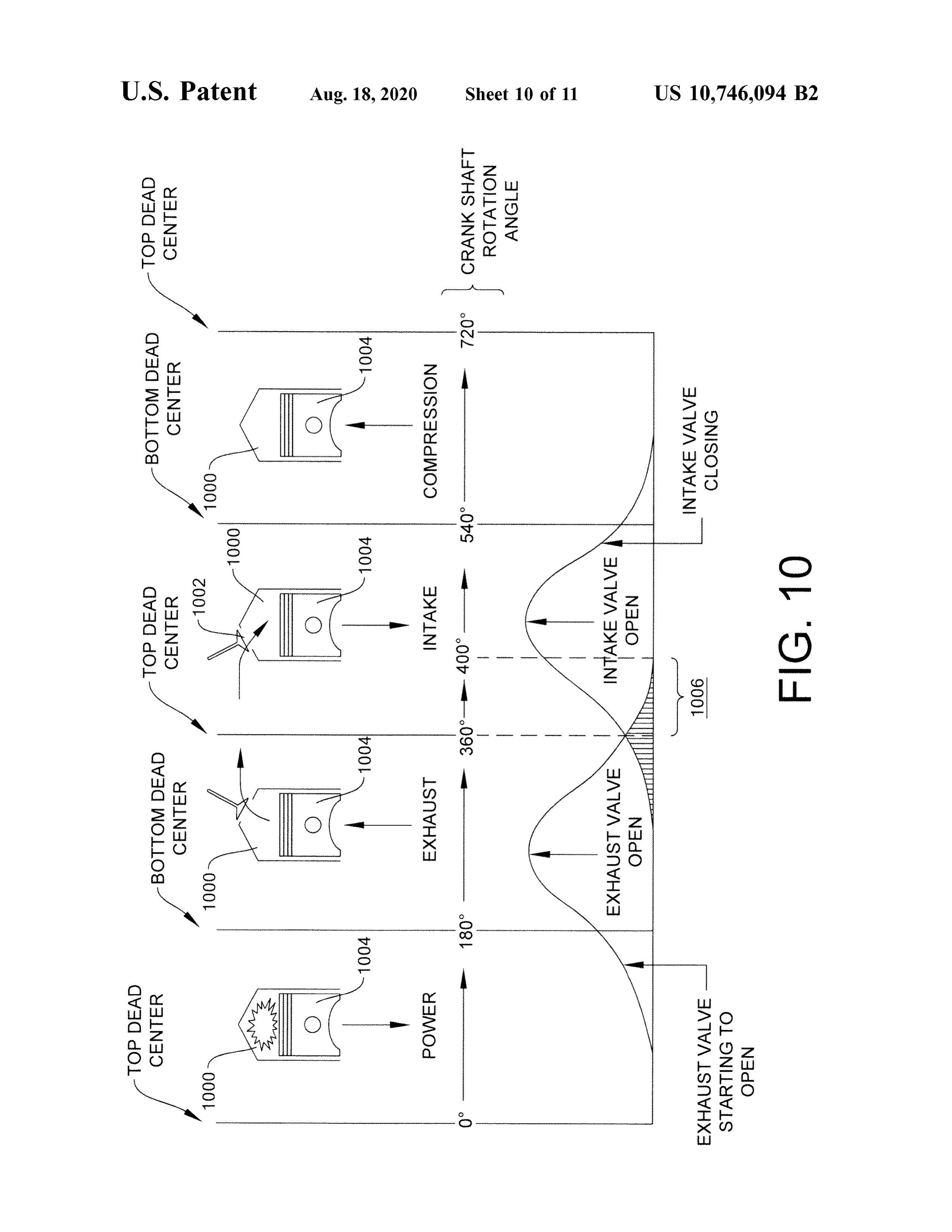
second injector of the plurality of injectors configured to In certain embodiments, for example, the method may deliver a second portion of the HHO gas supply to a second reduce engine -out emissions by at least 10 % ( for example by location about a second combustion chamber inlet of the 25 at least 20 % or at least 30% ) . The improvement in engine diesel engine; c ) at least a third injector of the plurality of out emissions may be relative to the internal combustion injectors configured to deliver at least a third portion of the engine running under identical or substantially identical HHO gas supply to at least a third location about at least a conditions ( for example , taking into account engine load , third combustion chamber inlet of the diesel engine; and d) average engine load , run -time, average run - time, tempera at least one further injector configured to deliver a further 30 ture, average temperature , speed, average speed, rpm's, portion of the HHO gas supply to a diesel particulate filter average rpm's, acceleration , average acceleration and / or ( DPF ) regenerator system . type of primary fuel) without HHO gas . In certain embodi Certain embodiments may provide, for example, a method ments, for example, the method may reduce particulate for increasing carbonaceous fuel economy of an internal emissions by at least 10% ( for example by at least 20 % or combustion engine. The improvement in fuel economy may 35 by at least 30% ) . In certain embodiments , for example, the berlative to the internal combustion enging under method may reduce soot emissions by at least 10 % ( for identical or substantially identical conditions ( for example , example by at least 20% or by at least 30 % ) . In certain taking into account engine load , average engine load , run embodiments, for example, the method may reduce a com time , average run - time, temperature , average temperature , bustion exhaust temperature by at least 10 ° F. ( for example speed , average speed , rpm's, average rpm's, acceleration , 40 by at least 20 ° F. or by least 30 ° F. ) . average acceleration and / or type of primary fuel) without In certain embodiments, for example, the delivered quan HHO gas . In certain embodiments, for example , the method tity of HHO gas may be no more than 500 ppm ( for example may comprise delivering a quantity of HHO gas in a stream in the range of 1-500 ppm , no more than 250 ppm , in the of oxygen -containing gas to at least one combustion cham range of 1-250 ppm , in the range of 1-100 ppm , in the range ber of the internal combustion engine during a portion of an 45 of 25-100 ppm , or in the range of 50-100 ppm) HHO gas intake stroke of at least one combustion cylinder of the relative to the weight of combusted carbonaceous fuel . internal combustion engine. In certain embodiments , for In certain embodiments , for example, the method may example, the portion may be less than 7 % ( for examples further comprise delivering a further quantity of HHO gas to than 50 % , less than 25 % , or in the range of 20-25 % of the a diesel particulate filter ( DPF ) regenerator system . In cer intake stroke ). In certain embodiments, for example, the 50 tain embodiments, for example, the quantity of HHO gas portion may be in the range of7-10% ofthe intake stroke. may be passed through a heat exchanger prior to the deliv In certain embodiments , for example, the portion may be ering. In certain embodiments , for example, the heat less than the whole intake stroke . In certain embodiments, exchanger may receive an engine exhaust stream . In certain for example, the during a portion of an intake stroke may be embodiments , for example, the heat exchanger may receive when the intake stroke is at an angle in the range of 0-40 ° 55 an engine coolant stream . In certain embodiments, for ( or 40-180 ° ) from top -dead -center. In certain embodiments, example, the delivered quantity of HHO gas may be fresh for example, the during a portion of an intake stroke may be ( for example the quantity of HHO gas may be delivered when the intake stroke is at an angle of at least 10 ° from within 5 hours of generation ( for example generation by top -dead -center electrolysis of an electrolyte solution) . In certain embodiments, for example, the internal com- 60 Certain embodiments may provide, for example , a method bustion engine may be a 4 - stroke engine. for delivering precision quantities of in - situ generated HHO In certain embodiments, for example, the HHO gas may gas about an internal combustion engine. In certain embodi be air - free prior to introduction to the stream of oxygen ments, for example, the method may comprise delivering containing gas. separate independent quantities of HHO gas during inde In certain embodiments, for example, the method may 65 pendent portions of at least two air intake strokes to at least improve fuel economy by at least ( for example at least two out- of - phase combustion cylinders of the internal com 20 % or at least 30 % ) . The improvement in fuel economy bustion engine. In certain embodiments, for example, the
Page 22
portions of the at least two air intake strokes may be less than Certain embodiments may provide, for example, a method 70 % of the complete air intake strokes for either of the air for delivering precision quantities of in - situ generated HHO intake strokes. gas about an internal combustion engine, comprising: deliv In certain embodiments, for example, the delivering the ering separate quantities of HHO gas during portions of at separate independent quantities of HHO gas may comprise: 5 least two air intake strokes to at least two out -of-phase delivering a first quantity of HHO gas during a portion of an combustion cylinders of the internal combustion engine. intake stroke of a first combustion cylinder, the portion of the intake stroke of the first combustion cylinder may be less forCertain embodiments may provide, for example , a method increasing carbonaceous fuel economy of an internal than 70 % ( for example , less than 60 % , less than 50% , or less combustion engine , comprising: i ) delivering a first quantity than 40%quantity a second ) of the complete air intake of HHO gas during stroke ; andofdelivering a portion an intake 10 of HHO gas in a first stream of oxygen - containing gas to stroke of a second combustion cylinder, the portion of the within 3 inches of a first combustion chamber inlet orifice of intake stroke of the second combustion cylinder may be less engine combustion a first during a chamber of the internal combustion portion of an intake stroke of a first than 70 % ( for example , less than 60 % , less than 50% , or less than 40%) of the complete air intake stroke; the intake stroke 15 combustion cylinder at an angle in the range of (-40° from of the first combustion cylinder being out of phase with the top -dead -center of the first combustion cylinder, the first combustion cylinder comprising the first combustion cham intake stroke of the second combustion cylinder.
In certain embodiments, for example, the delivering the ber ; ii ) delivering a second quantity of HHO gas in a second separate quantities of HHO gas may comprise: delivering a stream of oxygen -containing gas to within 3 inches of a first quantity of HHO gas during an intake stroke of a first 20 second combustion chamber inlet orifice of a second com combustion cylinder at a crankshaft angle in the range of bustion chamber of the internal combustion engine during a 0-40 ° from top -dead -center of the first combustion cylinder ; portion of an intake stroke of a second combustion cylinder and delivering a second quantity of HHO gas during an at an angle in the range of 0-40 ° from top -dead -center of the intake stroke of a second combustion cylinder at a crank second combustion cylinder, the second combustion cylin shaft angle in the range of 0-40 ° from top -dead -center of the 25 der comprising the second combustion chamber; and iii ) second combustion cylinder, the intake stroke of the first delivering at least a third quantity of HHO gas in at least a combustion cylinder out of phase with the intake stroke of third stream of oxygen -containing gas to at least a third the second combustion cylinder . combustion chamber inlet orifice of at least a third combus Certain embodiments may provide, for example, a method tion chamber of the internal combustion engine. The for increasing carbonaceous fuel economy of an internal 30 improvement in fuel economy may be relative to the internal combustion engine. The improvement in fuel economy may combustion engine running under identical or substantially be relative to the internal combustion engine running under identical conditions ( for example, taking into account engine identical or substantially identical conditions ( for example, load, average engine load , run - time, average ru tem taking into account engine load , average engine load , run perature, average temperature, speed, average speed, rpm's , time , average run - time, temperature, average temperature, 35 average rpm's, acceleration , average acceleration and / or speed, average speed , rpm's , average rpm's, acceleration , type of primary fuel) without HHO gas . average acceleration and / or type of primary fuel) without Certain embodiments may provide, for example , a system HHO gas. In certain embodiments , for example , the method to distribute an HHO gas supply to an internal combustion may comprise delivering a first quantity of HHO gas in a engine having a plurality of combustion chambers. In certain first stream of oxygen -containing gas to within 3 inches of 40 embodiments, for example, the system may comprise at least a first combustion chamber inlet orifice of a first combustion one injector among a plurality of injectors, the at least one chamber of the internal combustion engine during a portion injector configured to introduce at least a portion of the HHO of an intake stroke of a first combustion cylinder at an angle gas supply to within 3 inches of at least one combustion in the range of 0-40 ° from top - dead - center of the first chamber inlet of at least one combustion chamber of the combustion cylinder, the first combustion cylinder compris- 45 plurality of combustion chambers . In certain embodiments, ing the first combustion chamber. In certain embodiments, for example, the system may comprise a control system for example, the method may comprise delivering a second configured to control the at least one injector based on quantity of HHO gas in a second stream of oxygen - contain timing parameters for the at least one combustion chamber. ing gas to within 3 inches of a second combustion chamber In certain embodiments, for example, the control system inlet orifice of a second combustion chamber of the internal 50 may be configured to adjust timing and / or duration of the at combustion engine during a portion of an intake stroke of a least one injector in response to intake stroke timing of the second combustion cylinder at an angle in the range of 0-40 ° at least one combustion cylinder or a change in the intake from top -dead -center of the second combustion cylinder, the stroke timing . In certain embodiments, for example, the second combustion cylinder comprising the second combus control system may be configured to control the at least one tion chamber. In certain embodiments, for example, the 55 injector. In certain embodiments , for example, the control method may comprise delivering at least a third quantity of system may be configured to adjust timing and / or duration HHO gas in at least a third stream of oxygen -containing gas of the at least one injector in response to engine speed or a to at least a third combustion chamber inlet orifice of at least change in engine speed . In certain embodiments, for a third combustion chamber of the internal combustion example , the control system may be configured to adjust engine. 60 timing and / or duration of actuation of the at least one Certain embodiments may provide, for example, a method injector in response to engine load or a change in engine for increasing carbonaceous fuel economy of an internal load . In certain embodiments , for example, the control combustion engine, comprising: delivering a quantity of system may be configured to adjust timing and / or duration HHO gas in a stream of oxygen -containing gas to at least of actuation of the at least one injector in response to fuel one combustion cylinder of the internal combustion engine 65 consumption or a change in fuel consumption. In certain during a portion of an intake stroke ( for example less than embodiments, for example , the control system may be a full intake stroke) of the at least one combustion cylinder. configured to adjust timing and / or duration of actuation of
Page 23
the at least one injector when an exhaust temperature of the timing and / or duration of actuation of the at least one internal combustion engine exceeds a predicted temperature . injector in response to exhaust temperature or a change in In certain embodiments, for example, the control system exhaust temperature. In certain embodiments, for example, may comprise a processor, the processor configured to the control system may be configured to adjust timing and / or compute an HHO gas quantity required to reduce one or 5 duration of actuation of the at least one injector in response more engine -out emissions to a predetermined level . The to input from a fuel injector sensor or a change in input from improvement in engine - out emissions may be relative to the a fuel injector sensor. In certain embodiments, for example, internal combustion engine running under identical or sub the control system may be configured to adjust timing and / or stantially identical conditions ( for example, taking into account engine load , average engine load , run - time, average 10 toduration of actuation of the at least one injector in response run -time, temperature, average temperature, speed, average RPM sensor. an RPM sensor or a change in input from an input from speed, rpm's , average rpm's, acceleration , average accelera In certain embodiments, for example, the at least one tion and / or type of primary fuel) without HHO gas .
embodiments, for example, the control system injector may be equipped with a metal tube to carry air - free mayIn certain be configured to adjust timing and /or duration of 15 HHO gas to within 3 inches of a first combustion chamber inlet of the at least one combustion chamber inlet . In certain actuation of the at least one injector of the plurality of injectors when an HHO gas temperature reading input from embodiments, for example, the metal tube may have a a temperature sensor exceeds a predetermined level . In soldered end with an orifice drilled therethrough . In certain certain embodiments , for example, the control system may embodiments, for example, the orifice may have an orifice be configured to adjust timing and /or duration of actuation 20 diameter in the range of 10-50 thousandths of an inch . In of the at least one injector of the plurality of injectors when certain embodiments, for example , the system may be an HHO gas pressure reading input from a pressure sensor cooperatively configured with the internal combustion exceeds a predetermined level . In certain embodiments, for engine whereby a distal end of the metal tube is free - floating example, the control system may be configured to actuate inside an air intake manifold .
the plurality of injectors in a sequence whether an air intake 25 In certain embodiments, for example , the plurality of valve is open. injectors may be connected together in a daisy chain to In certain embodiments, for example, the control system receive power for actuation in a predetermined sequence . may be configured to actuate the plurality of injectors in In certain embodiments, for example, each injector of the response to at least the camshaft rotation of an internal plurality of injectors may comprise an injector solenoid . In combustion engine and /or at least one predetermined posi- 30 certain embodiments, for example, each injector of the tion of the camshaft . In certain embodiments, for example, plurality of injectors may be actuated by 1-20 milliamps of the control system may be further configured to actuate the electric current. In certain embodiments, for example, the plurality of injectors in response an engine temperature plurality of injectors may be actuated for 1-3 milliseconds measurement. In certain embodiments, for example, the per engine cylinder cycle ( for example per engine cylinder control system may be configured to prevent actuation of the 35 cycle of a 4 - stroke engine cycle) . plurality of injectors until an engine temperature is measured In certain embodiments, for example , the system to dis having at least a minimum predetermined value . tribute an HHO gas supply may further comprise at least one In certain embodiments, for example, the control system further injector, the at least one further injector configured to may be configured to actuate the plurality of injectors deliver a further portion of the received HHO gas supply to simultaneously. In certain embodiments, for example, the 40 a diesel particulate filter (DPF) regenerator system . control system may be configured to actuate the at least one In certain embodiments, for example, a first injector of the injector at a first time and a second injector of the plurality at least one injector may be configured to deliver the at least of injectors at a second time , the first time different from the a portion of the HHO gas during a portion of an intake stroke second time . of a first combustion cylinder. In certain embodiments , for In certain embodiments, for example, the system to dis- 45 example, the portion of an intake stroke is less than 50% of tribute an HHO gas supply may be configured to introduce the intake stroke. In certain embodiments, for example, the the at least a portion of the HHO gas supply at a controlled during a portion of an intake stroke is when the intake stroke temperature and pressure . In certain embodiments, for is at an angle in the range of 0-40 ° from top -dead -center. example, the system to distribute HHO gas may further Certain embodiments may provide, for example , a system comprise a heat exchanger, the heat exchanger configured to 50 to distribute an HHO gas supply to an internal combustion receive at least a portion of the HHO gas supply . In certain engine. In certain embodiments, for example , the system embodiments , for example, the pressure of the introduced at may comprise a first injector configured to deliver a first least a portion of the HHO gas supply may be controlled portion of the HHO gas supply to within 3 inches of a first relative to a gas intake pressure of the internal combustion combustion chamber inlet of the internal combustion engine. engine. 55 In certain embodiments, for example, the system may com In certain embodiments, for example, the control system prise a second injector configured to deliver a second portion may be configured to adjust timing and / or duration of of the HHO gas supply to within 3 inches of a second actuation of the at least one injector in response to throttle combustion chamber inlet of the internal combustion engine. position or a change in throttle position . In certain embodi In certain embodiments, for example, the system may com ments, for example, the control system may be configured to 60 prise at least a third injector configured to deliver at least a adjust timing and / or duration of the at least one injector in third portion of the HHO gas supply to within 3 inches of at response to intake manifold pressure or a change in intake least a third combustion chamber inlet of the internal com manifold pressure. In certain embodiments, for example , the bustion engine. In certain embodiments , for example, the control system may be configured to adjust timing and /or system may comprise a control system configured to control duration of actuation of the at least one injector based on 65 the actuation of each injector among the plurality of injec inputs from a knock sensor. In certain embodiments, for tors based on parameters for the corresponding combustion example, the control system may be configured to adjust chamber in the internal combustion engine.
Page 24
Certain embodiments may provide, for example, a system ft -lb peak torque. In certain embodiments, for example, the to distribute an HHO gas supply to an internal combustion heavy duty diesel engine may be sized to produce in the engine having a plurality of combustion chambers , compris range of 400-700 hp ( for example 430-500 hp ). ing : i ) at least one injector among a plurality of injectors, the In certain embodiments, for example, the over - the - road at least one injector configured to introduce at least a portion 5 heavy duty truck may be a Class 8 vehicle. In certain of the HHO gas supply to within 3 inches of at least one embodiments, for example , the over -the - road heavy duty combustion chamber inlet of at least one combustion cham truck may be a Class 9 vehicle . ber of the plurality of combustion chambers ; and ii ) a control In certain embodiments , for example, the quantity of system configured to control the at least one injector based on timing parameters for the at least one combustion cham- 10 electrolyte solution may be sufficient for at least 5,000 miles ( for example at least 10,000 miles , at least 20,000 miles , at ber .
Certain embodiments may provide, for example, a system least 30,000 miles , or at least 40,000 miles ) of driving. to distribute an HHO gas supply to an internal combustion may becertainIn embodiments, for example, the first chamber configured to contain at least 1/4 gallon ( for example engine, comprising: i ) a first injector configured to deliver a first portion of the HHO gas supply to within 3 inches of a 15 5 gallons , or at leastleast at least 1/2 gallon , at 1 gallon , at least 2 gallons , at least 10 gallons ) of the electrolyte.
first combustion chamber inlet of the internal combustion engine; ii ) a second injector configured to deliver a second In certain embodiments, for example, the onboard HHO portion of the HHO gas supply to within 3 inches of a second generator may further comprise a controller, the controller combustion chamber inlet of the internal combustion engine; configured to control at least a power supply to the elec iii) at least a third injector configured to deliver at least a 20 trolysis cell . In certain embodiments, for example, the third portion of the HHO gas supply to within 3 inches of at controller may be configured to control the power supply to least a third combustion chamber inlet of the internal com maintain the quantity of the electrolyte solution at a tem bustion engine; and iv ) a control system configured to perature in the range of 80-150 ° F. ( for example a tempera control the actuation of each injector among the plurality of ture in the range of 90-120 ° F. , in the range of 95-115 ° F. , injectors based on parameters for the corresponding com- 25 in the range of 100-115 ° F. , or a temperature in the range of bustion chamber in the internal combustion engine. 100-110 ° F. ) . In certain embodiments, for example, the Certain embodiments may provide, for example, an controller may be configured to control the power supply to onboard HHO generator for an over - the - road heavy duty maintain the second chamber at a pressure in the range of truck powered by a heavy duty diesel engine. In certain 30-60 psig ( for example in the range of 40-55 psig , in the embodiments, for example, the onboard HHO generator may 30 range of 44-50 psig , or in the range of 45-50 psig ) . comprise a dual - chamber vessel in communication with an In certain embodiments, for example, the second chamber internal combustion engine powering the heavy duty truck . may be cooperatively configured with the first chamber to In certain embodir ents, for example, the dual -chamber receive the supply of HHO gas from the first chamber and vessel may comprise an electrolysis cell in a first chamber of to store a portion of the supply of HHO gas . In certain the dual- chamber vessel , the first chamber containing a 35 embodiments, for example, the second chamber may be quantity of electrolyte solution , the quantity of electrolyte configured to store at least a 10 minute supply ( for example solution sufficient to produce a supply of HHO gas for at least a 20 minute supply, at least a 30 minute supply, or 60,000,000 crankshaft rotations of the internal combustion at least a 1 hour supply ) of HHO gas for use by the internal engine. In certain embodiments, for example, the dual combustion engine based on an average load of 200 hp, the chamber vessel may comprise a second chamber containing 40 internal combustion engine having a displacement of at least HHO gas and a quantity of replacement electrolyte solution , 10 liters . In certain embodiments, for example, the second the contained HHO gas and the quantity of replacement chamber may have a volume at least as large as the volume electrolyte solution sharing a free surface, the first chamber of the first chamber.
and the second chamber in continuous liquid communica In certain embodiments, for example, the first chamber tion, the second chamber disposed between the first chamber 45 may be cooled by engine coolant.
and the internal combustion engine. In certain embodiments, for example, the electrolysis cell In certain embodiments, for example, the onboard gen may comprise electrodes, the electrodes comprising iridium erator may be in communication ( for example fluid com coated on titanium .
munication) with at least one combustion chamber of the In certain embodiments, for example, the HHO generator heavy duty diesel engine. In certain embodiments, for 50 may be configured to provide HHO gas for at least 50 hours example, a first injector may be configured to deliver the at ( for example at least 100 hours, at least 200 hours , or at least least a portion of the HHO gas during a portion of an intake 500 hours ) operation of the truck based on the quantity of stroke of a first combustion cylinder, the first combustion electrolyte . In certain embodiments, for example , the HHO cylinder comprising a first combustion chamber of the at generator may be configured to provide HHO gas for at least least one combustion chamber. In certain embodiments, for 55 5,000 miles ( for example at least 10,000 miles , 20,000 miles , example , the portion of the intake stroke may be less than 30,000 miles , or at least 50,000 miles ) operation of the truck 50 % of the intake stroke . In certain embodiments, for based on the quantity of electrolyte.
example, the during a portion of an intake stroke may be In certain embodiments, for example, the controller may when the intake stroke is at an angle in the range of 0-40 ° be configured to control the power supply to cause the from top - dead - center. 60 electrolysis cell to produce HHO gas intermittently to main In certain embodiments , for example, the heavy duty tain a temperature of the electrolyte and a pressure in the diesel engine may have a displacement in the range of 11-16 second chamber. In certain embodiments , for example , the liters . maintained temperature may be in the range of 80-150 ° F. In certain embodiments, for example, the heaving duty ( for example a temperature in the range of 90-120 ° F. , in the diesel engine may be sized for an engine speed of at least 65 range of 95-115 ° F. , in the range of 100-115 ° F. , or a 1800 rpm . In certain embodiments, for example, the heavy temperature in the range of 100-110 ° F. ) . In certain embodi duty diesel engine may provide in the range of 1600-2000 ments, for example, the maintained pressure may be in the
Page 25
range of 30-60 psig ( for example in the range of 40-55 psig , configured to produce HHO gas . In certain embodiments , for in the range of 44-50 psig , or in the range of 45-50 psig ) . example , the vessel may comprise a replaceable pressure In certain embodiments, for example, the first chamber retaining and relief system , the replaceable pressure retain and the second chamber may be in continuous liquid com ing and relief system configured to — a ) retain the reusable munication , the second chamber disposed between the first 5 container components in a fixed configuration when the chamber and the internal combustion engine. contents of the vessel are below a relief pressure ; and b ) In certain embodiments, for example, the onboard HHO allow reuse of the reusable container components without generator may be in communication with at least one repair by releasing contents of the vessel at the relief injector, the at least one injector configured to deliver at least pressure .
a portion of the supply of HHO gas to a diesel particulate 10 In certain embodiments, for example, the replaceable filter (DPF ) regenerator system . In certain embodiments, for pressure retaining and relief system may operate to relieve example, the onboard HHO generator may be in communi the relief pressure within 50 ms (for example in less than 10 cation with a plurality of injectors, the plurality of injectors ms , less than 5 ms , less than 1 ms , or less than 0.1 ms). configured to introduce at least a portion of the HHO gas to
at least one combustion chamber inlet of the diesel engine. 15 pressure certain embodiments, for example, the replaceable In certain embodiments, for example , the plurality of retaining and relief system may be configured to injectors may comprise: i ) a first injector configured to open the vessel at least 1 % ( for example in the range of deliver a first portion of the HHO gas to within 3 inches of 1-3 % , at least 2 % , at least 3 % , at least 5 % , or at least 10% ) , a first combustion chamber inlet of the diesel engine ; ii ) a relative to a surface area of the vessel , in less than 50 ms ( for second injector configured to deliver a second portion of the 20 example in less than 10 ms , less than 5 ms , less than 1 ms , HHO gas to a second combustion chamber inlet of the diesel or less than 0.1 ms ) of contents of the vessel reaching the engine; and iii ) at least a third injector configured to deliver pre -designed relief pressure . In certain embodiments, for at least a third portion of the HHO gas to at least a third example , the replaceable pressure retaining and relief sys combustion chamber inlet of the diesel engine. tem may be configured to retain HHO gas within a storage In certain embodiments, for example , the onboard HHO 25 pressure range .
generator may be in communication with a heat exchanger, In certain embodiments, for example, the second chamber the heat exchanger configured to receive at least a portion of may be in continuous fluid communication with the first the HHO gas . In certain embodiments, for example , the heat chamber, the second chamber configured to store at least a exchanger may be configured to receive an engine exhaust portion of the produced HHO gas . In certain embodiments, stream . In certain embodiments, for example , the heat 30 for example , the vessel may be configured for passive exchanger may be configured to receive an engine coolant transport of HHO gas from the first chamber to the second stream . chamber. In certain embodiments, for example, the second In certain embodiments , for example, the first chamber chamber may be configured to contain less than a 5 hour and the second chamber may be in continuous communica supply ( for example in the range of a 10-30 minute supply, tion via a small size orifice ( for example less than 5 % of the 35 less than a 2 hour supply, less than a 1 hour supply, less than surface area of the free surface ). In certain embodiments, for a 30 minute supply, or less than a 10 minute supply ) hour example, the first chamber and the second chamber may be supply of HHO gas .
in restricted fluid communication. In certain embodiments, for example, a controller may be In certain embodiments, for example, the quantity of configured to control an electricity supply to the electrolysis electrolyte solution may be sufficient to produce a supply of 40 cell to maintain a volume of HHO gas in the second chamber HHO gas for 60,000,000 crankshaft rotations of the internal within the storage pressure rage .
combustion engine at an average load of 200 hp . In certain embodiments, for example, the replaceable Certain embodiments may provide, for example , an pressure retaining and relief system may comprise a pressure onboard HHO generator for an over - the - road heavy duty release member, the pressure release member sized to truck powered by a heavy duty diesel engine, comprising: a 45 release at least a portion of the contents of the vessel when dual - chamber vessel in communication with an internal the vessel pressure reaches the relief pressure . In certain combustion engine powering the heavy duty truck , compris embodiments, for example, the pressure release member ing : i ) an electrolysis cell in a first chamber of the dual may be non -reclosing. In certain embodiments, for example, chamber vessel , the first chamber containing a quantity of the pressure release member may be configured to open the electrolyte solution , the quantity of electrolyte solution 50 second chamber. In certain embodiments, for example , the sufficient to produce a supply of HHO gas for 60,000,000 relief pressure may be less than the lowest failure point of crankshaft rotations of the internal combustion engine; and the vessel components.
ii ) a second chamber containing HHO gas and a quantity of In certain embodiments, for example, the replaceable replacement electrolyte solution , the contained HHO gas pressure retaining and relief system may comprise at least and the quantity of replacement electrolyte solution sharing 55 one elongated retaining member. In certain embodiments, a free surface, the first chamber and the second chamber in for example, the at least one elongated retaining member continuous liquid communication , the second chamber dis may comprise a tie rod . In certain embodiments, for posed between the first chamber and the internal combustion example , the at least one elongated retaining member may engine. comprise an all -thread rod . In certain embodiments, for Certain embodiments may provide, for example, a dual- 60 example, the at least one elongated retaining member may chamber electrolysis vessel configured for safe generation stretch by at least 3/16 inch at the relief pressure . In certain and storage of HHO gas for use by an internal combustion embodiments, for example, the replaceable pressure retain engine. In certain embodiments, for example, the vessel may ing and relief system may be configured to open the vessel comprise reusable container components, at least one of the when the at least one elongated retaining member yields . reusable container components dividing an interior of the 65 In certain embodiments, for example, the reusable con vessel into a first chamber and a second chamber, the first tainer components may comprise: a first endplate , a first chamber containing an electrolysis cell , the electrolysis cell hollow outer casing , a second hollow outer casing, and a
Page 26
middle plate disposed between the first hollow outer casing injector configured to deliver a first portion of the HHO gas and the second hollow outer casing . to within 3 inches of a first combustion chamber inlet of a In certain embodiments, for example, first and second first combustion chamber of the internal combustion engine; cylindrical members may be pressed against a circular ii ) a second injector configured to deliver a second portion middle plate disposed there between via plural elongated 5 of the HHO gas to a second combustion chamber inlet of a retaining members symmetrically distributed about the first second combustion chamber of the internal combustion and second cylindrical members, a first portion of the plural engine; and iii ) at least a third injector configured to deliver elongated retaining members passing through first apertures at least a third portion of the HHO gas to at least a third of a flange member of the first cylindrical member and first combustion chamber inlet of at least a third combustion apertures of the middle plate , a second portion of the plural 10 chamber of the internal combustion engine. elongated retaining members passing through second aper In certain embodiments, for example , the vessel may be in tures of the middle plate and apertures of a top plate, the top communication with a heat exchanger, the heat exchanger plate pressed against the second cylindrical member. In configured to receive at least a portion of the HHO gas . In certain embodiments, for example , the vessel may comprise certain embodiments, for example, the heat exchanger may a pressure release member, wherein the pressure release 15 be configured to receive an engine exhaust stream . In certain member is the top plate of the second chamber. In certain embodiments, for example , the heat exchanger may be embodiments, for example, the first and second cylindrical configured to receive an engine coolant stream . members may each have a diameter in the range of 4-12 In certain embodiments , for example, the first injector inches . In certain embodiments, for example, the non may be configured to deliver the first portion of the HHO gas reclosing pressure release member may be sized to form a 20 during a portion of an intake stroke of a first combustion vent area of at least 20 cm2 within 0.1 milliseconds at the cylinder, the first combustion cylinder comprising the first third pressure . In certain embodiments, for example, the top combustion chamber. In certain embodiments , for example, plate may be constructed of 3/8 inch stainless steel . In certain the portion of an intake stroke may be less than 50% of the embodiments, for example , the middle plate may be con intake stroke. In certain embodiments , for example, the structed of a polyoxymethylene material . In certain embodi- 25 during a portion of an intake stroke may be when the intake ments , for example , the elongated retaining members may stroke is at an angle in the range of 0-40 ° from top -dead bel1 - threadrdfastened withcknut certainmdi center.
ment , for example , the locknut maybe tightened to Certain embodiments may provide, for example, a dual true in the range of 50-10 -in . chamber electrolysis vessel configured for safe storage of In certain embodiments, for example , the pressure relief 30 HHO gas for use by an internal combustion engine. In system may be configured to open the vessel upon detona certain embodiments, for example , the vessel may comprise tion of HHO gas in the first chamber and /or the second an electrolysis cell in a first chamber of the dual - chamber chamber . essel, the electrolysis cell configured to produce HHO gas . In certain embodiments, for example, the vessel may be In certain embodiments, for example , the vessel may com adapted for installation onboard a vehicle. In certain 35 prise a pressure release member, the pressure release mem embodiments , for example, the vessel may be adapted for ber configured to form an opening in communication with a safe storage of HHO when the vehicle is moving . pressure relief space when a pressure inside the vessel In certain embodiments, for example , the replaceable exceeds a predetermined pressure , the opening having a pressure retaining and relief system may be configured to surface area of at least 2 % ( for example at least 3 % , at least form a vent area at the top of the second chamber. 40 5 % , or at least 10 % ) the surface area of the vessel , the In certain embodiments, for example, the vessel may opening effective to bring the pressure of the vessel to a contan oling coils in the first chamber. pressure of the relief space in less than 50 ms ( for example In certain embodiments, for example, the electrolysis cell in less than 10 ms , less than 5 ms , less than 1 ms , or less than may comprise electrodes, wherein a controller is configured 0.1 ms ) .
to control an electricity supply to the to the electrolysis cell 45 In certain embodiments, for example, the electrolysis cell to provide a current density to the electrodes of 25-100 may be configured to produce HHO gas at a first pressure or mA / cm2. In certain embodiments , for example, a controller within a range of pressures, for example the electrolysis cell may be configured to control an electricity supply to the to may be in communication with a control system which the electrolysis cell to provide a voltage in the range of 11-15 controls a supply of electricity to the electrolysis cell based VDC . 50 on a pressure in a vapor space of the second chamber, In certain embodiments , for example, a controller may be whereby a supply of electricity for generation of HHO gas configured to control an electricity supply to the to the is provided only when the pressure in the vapor space falls electrolysis cell to maintain a temperature in the first cham in below said first pressure or said range of pressures . In ber of less than 65 ° C. certain embodiments, for example, the vessel may comprise In certain embodiments, for example , the relief pressure 55 a second chamber, the second chamber in continuous fluid maybe 150psgrmore, communication with the first chamber , the second chamber In certain embodiments, for example, the vessel may be in configured to store at least a portion of the produced HHO communication with at least one injector, the at least one gas . In certain embodiments , for example, the vessel may be injector configured to deliver at least a portion of the HHO configured for passive transport of HHO gas from the first gas to an internal combustion particulate filter (DPF ) regen- 60 chamber to the second chamber. In certain embodiments, for erator system . example, the second chamber may be configured to contain In certain embodiments, for example, the vessel may be in a less than 5 hour supply ( for example less than a 2 hour communication with a plurality of injectors, the plurality of supply, less than a 1 hour supply , less than a 30 minute injectors configured to introduce at least a portion of the supply, or less than a 10 minute supply) of HHO gas . In HHgas at least one combustion chamber inlet of the 65 certain embodimet , for example, controler may be internal combustion engine. In certain embodiments, for configured to control an electricity supply to the to the example , the plurality of injectors may comprise : i ) a first electrolysis cell to maintain a pressure and an amount HHO
Page 27
gas in the second chamber. In certain embodiments, for In certain embodiments, for example, a controller may be example, the vessel may comprise a relief valve , the relief configured to control an electricity supply to the to the valve sized to release at least a portion of the contents of the electrolysis cell to provide a voltage in the range of 11-15 second chamber at a second pressure , the second pressure VDC .
greater than the first pressure . In certain embodiments, for 5 In certain embodiments , for example, a controller may be example , the pressure relief member may be non - reclosing . configured to control an electricity supply to the to the In certain embodiments, for example, the pressure release ber electrolysis cell to maintain a temperature in the first cham member may be configured to open the second chamber. In of less than 65 ° C.
certain embodiments, for example, the predetermined pres 10 or precertain
embodiments , for example , the predetermined designed pressure may be 1500 psig or more .
sure may be less than the failure point of the other compo In certain embodiments , for example , the pressure release nents of the vessel . In certain embodiments, for example, the member may comprise a top endcap of the second chamber. first chamber and the second chamber may be secured to one Certain embodiments may provide, for example, a dual another by at least one elongated retaining member. In chamber electrolysis vessel configured for safe storage of certain embodiments , for example , the at least one elongated 15 HHO gas for use by an internal combustion retaining member may comprise a tie rod . In certain embodi prising: i ) reusable container components , at least engine, com one of the ments, for example, the at least one elongated retaining reusable container components dividing an interior of the member may comprise an all - thread rod. In certain embodi vessel into a first chamber and a second chamber, the first ments, for example, the at least one elongated retaining chamber containing an electrolysis cell , the electrolysis cell member may stretch by at least 3/16 inch at the predetermined 20 configured to produce HHO gas ; and ii ) a replaceable pressure. In certain embodiments , for example, the non pressure retaining and relief system , the replaceable pressure reclosing pressure release member may be configured to retaining and relief system configured to—a) retain the open when the at least one elongated retaining member reusable container components in a fixed configuration when yields . In certain embodiments, for example , the first and the contents of the vessel are below a relief pressure ; and b ) second chambers may be cylindrical. In certain embodi- 25 allow reuse of the reusable container components without ments, for example, the first and second chambers may each repair by releasing contents of the vessel at the relief be pressed against a circular middle plate via plural elon pressure .
gated retaining members symmetrically distributed about Certain embodiments may provide, for example , a method the first and second chambers, a first portion of the plural for providing HHO gas to an internal combustion engine . In elongated retaining members passing through first apertures 30 prise certain embodiments, for example, the method may com controlling a delivery temperature of the HHO gas by of a flange member of the first chamber and first apertures exchanging of the middle plate , a second portion of the plural elongated stream of theheat between the HHO gas and an exhaust gas retaining members passing through second apertures of the ments, for example, thecombustion internal engine. In certain embodi middle plate and apertures of a top plate of the second 35 HHO gas at the deliverymethod may comprise delivering the temperature to at least one com chamber. In certain embodiments, for example, the top plate bustion chamber of the internal combustion engine. of the second chamber may be the pressure release member. In certain embodiments, for example, the method may In certain embodiments, for example, the first and second further comprise powering a vehicle with the internal com chambers may each have a diameter in the range of 4-12 bustion engine.
inches . In certain embodiments, for example, the non- 40 In certain embodiments , for example, the HHO gas may reclosing pressure release member may be sized to form a be produced by an onboard electrolysis unit. vent area of at least 20 cm2 within 0.1 milliseconds at the In certain embodiments, for example, the controlling may third pressure. In certain embodiments, for example, the top comprise passing HHO gas from a gas outlet of the onboard plate may be constructed of 3/8 inch stainless steel . In certain electrolysis unit to a heat exchanger. In certain embodi embodiments, for example, the middle plate may be con- 45 ments, for example , the exhaust gas stream may be passed structed of Delrin® . In certain embodiments, for example, through the heat exchanger. In certain embodiments, for the elongated retaining members may be all - thread rods example, the temperature of the exhaust gas stream may be fastened with lock nuts . In certain embodiments, for reduced by at least 30 ° F.
example, the lock nuts may be tightened to a torque in the In certain embodiments, for example, the controlling may range of 50-100 lb -in . 50 increase the temperature of the HHO gas stream by at least In certain embodiments , for example, the pressure release 150 ° F.
member may be configured to open upon detonation of HHO In certain embodiments , for example , the heated HHO gas gas in the first chamber and /or the second chamber. may be delivered to the combustion chamber at a controlled In certain embodiments, for example, the vessel may be temperature . In certain embodiments , for example, the deliv adapted for installation onboard a vehicle . In certain 55 ery temperature may be based on a predetermined set point. embodiments, for example, the vessel may be adapted for In certain embodiments, for example, the heated HHO gas safe storage of HHO when the vehicle is moving . stream may be delivered to the combustion chamber at a In certain embodiments, for example, the pressure release temperature and a pressure to deliver a predetermined member may be configured to form vent area at the top of amount of HHO gas . In certain embodiments, for example , the second chamber. 60 the heat may be exchanged in a shell and tube heat In certain embodiments , for example, the vessel may exchanger. In certain embodiments, for example, the HHO contain cooling coils in the first chamber. gas may pass through a tube portion of the heat exchanger In certain embodiments, for example, the electrolysis cell and the exhaust gas stream may pass through a shell portion may comprise electrodes, wherein a controller is configured of the heat exchanger. In certain embodiments, for example, to control an electricity supply to the to the electrolysis cell 65 the tube portion may comprise a single straight tube. In to provide a current density to the electrodes of 25-100 certain embodiments, for example, the HHO gas may have mA / cm2. a pressure drop of less than 0.05 psi in the heat exchanger.
Page 28
Certain embodiments may provide, for example, a method In certain embodiments, for example , the heated HHO gas for providing HHO gas to an internal combustion engine. In stream may be delivered to the combustion chamber at a certain embodiments, for example, the method may com temperature and a pressure ( for example at a temperature in prise controlling a delivery temperature of the HHO gas by the range of 100-175 ° F. and a pressure in the range of exchanging heat between the HHO gas and an exhaust gas 5 20-150 psig ) to deliver a predetermined amount ofHHO gas . In certain embodiments, for example, the heat may be stream of the internal combustion engine. In certain embodi exchanged ments, for example, the method may comprise delivering a embodiments in a shell and tube heat exchanger. In certain first portion of the HHO gas at the delivery temperature to a tube portion, of for example , the HHO gas may pass through the heat exchanger and the exhaust passes a first combustion chamber of the internal combustion 10 through a shell portion engine, a second portion of the HHO gas at the delivery embodiments, for exampleof, the the heat exchanger. In certain temperature to a second combustion chamber of the internal single straight tube. In certain tube portion may comprise a embodiments , for example, combustion engine, and at least a third portion of the HHO the HHO gas has a pressure drop of less than gas at the delivery temperature to at least a third combustion example less than 0.25 psi , less than 0.1 psi , or less1than psi ( for
chamber of the internal combustion engine. 15 psi ) in the heat exchanger .
In certain embodiments, for example, the HHO gas may Certain embodiments may provide, for example, a method be further delivered to a diesel particulate filter (DPF ) for providing HHO gas to an internal combustion engine . In regenerator system . certain embodiments , for example, the method may com In certain embodiments, for example, the HHO gas may prise exchanging heat with exhaust of the internal combus be introduced to a first combustion chamber of the at least 20 tion engine to control the temperature of the HHO gas one combustion chamber during a portion of an intake stroke delivered to a first combustion chamber of the internal of a first combustion cylinder, the first combustion cylinder combustion engine, a second combustion chamber of the comprising the first combustion chamber. In certain embodi internal combustion engine, and at least a third combustion ments, for example , the portion of the intake stroke is less chamber of the internal combustion engine. than 50 % of the intake stroke. In certain embodiments, for 25 Certain embodiments may provide, for example, a method example, the during a portion of an intake stroke may be for providing HHO gas to an internal combustion engine, when the intake stroke is at an angle in the range of 0-40 ° comprising: i ) controlling a delivery temperature of the from top - dead -center. HHO gas by exchanging heat between the HHO gas and an Certain embodiments may provide, for example, a method exhaust gas stream of the internal combustion engine; and ii ) for providing HHO gas to an internal combustion engine. In 30 delivering the HHO gas at the delivery temperature to at certain embodiments, for example, the method may com least one combustion chamber of the internal combustion prise exchanging heat with exhaust of the internal combus engine.
tion engine to control the temperature of the HHO gas Certain embodiments may provide, for example, a method delivered to at least one combustion chamber of the internal for providing HHO gas to an internal combustion engine, combustion engine. 35 comprising: i ) controlling a delivery temperature of the In certain embodiments, for example, the method may HHO gas by exchanging heat between the HHO gas and an further comprise powering a vehicle with the internal com exhaust gas stream of the internal combustion engine; and ii ) bustion engine. In certain embodiments , for example , the delivering a first portion of the HHO gas at the delivery HHO gas stream may be produced by an onboard electroly temperature to a first combustion chamber of the internal sis unit . In certain embodiments, for example, the indirectly 40 combustion engine, a second portion of the HHO gas at the exchanging heat may comprise the exhaust exchanging heat delivery temperature to a second combustion chamber of the with a heat exchanger connected to a gas outlet of the internal combustion engine, and at least a third portion of the onboard electrolysis unit . HHO gas at the delivery temperature to at least a third In certain embodiments, for example, the indirectly combustion chamber of the internal combustion engine. exchanging heat may comprise the exhaust exchanging heat 45 Certain embodiments may provide, for example, an abate with a heat exchanger connected to a gas outlet of the ment system for an electrolysis unit onboard a vehicle , onboard electrolysis unit. comprising: a container having a partition between an elec In certain embodiments, for example, the temperature of trolysis chamber and an HHO gas collection chamber, the the exhaust may be reduced by at least 10 ° F. ( for example partition comprising a valve - free orifice , the electrolysis at least 20 ° F. , at least 30 ° F. , or at least 40 ° F. ) relative to 50 chamber configured to house a plurality of electrodes. In an internal combustion engine running under identical or certain embodiments , for example , the system may be substantially identical conditions ( for example, taking into effective to maintain the plurality of electrodes immersed in account engine load , average engine load , run - time, average a liquid electrolyte throughout all orientations of the con run - time, temperature, average temperature, speed, average tainer when a liquid level is filled to at least the indicated speed, rpm's, average rpm's, acceleration, average accelera- 55 minimum liquid level .
tion and / or type of primary fuel) without HHO gas . Certain embodiments may provide, for example, an elec In certain embodiments, for example, the temperature of trolysis system container for a vehicle . In certain embodi the heated HHO gas stream may be at least 125 ° F. ( for ments, for example , the electrolysis system container may example at least 150 ° F. ) . comprise a first chamber of the container containing an In certain embodiments, for example, the heated HHO gas 60 electrolysis generator, the electrolysis generator configured may be delivered to the combustion chamber at a controlled to produce HHO gas . In certain embodiments, for example, temperature. In certain embodiments, for example , the the electrolysis system container may comprise a second heated HHO gas stream may be delivered to the combustion chamber of the container in fluid communication with the chamber at a predetermined temperature or proximate the first chamber, the second chamber configured to receive and predetermined temperature or within a predetermined tem- 65 store HHO gas from the first chamber. In certain embodi perature range ( for example at a temperature in the range of ments, for example, the electrolysis system container may 100-175 ° F. ) comprise a rollover abatement system configured to seal off
Page 29
HHO gas from returning to the first chamber from the plural electrolysis electrodes. In certain embodiments, for second chamber under any orientation of the container. example, the electrolysis system may comprise a second In certain embodiments, for example, the rollover abate chamber having a height H and a diameter D , the height H ment system may have no moving parts. In certain embodi greater than the diameter D , the second chamber in fluid ments, for example, the container may have terminals for a 5 communication with the first chamber. In certain embodi power supply . In certain embodiments, for example, the ments , for example , the electrolysis system may comprise an container may be coupled to a control system for the power elongated dual -purpose nozzle configured to passively com supply . municate ( for example fluidly communication via buoyancy In certain embodiments, for example, the electrolysis forces) liquid electrolyte and HHO gas between the first system container may further comprise a pressure retaining 10 chamber and the second chamber, the elongated dual-pur and relief system , the pressure retaining and relief system pose nozzle defining an outlet disposed within the second configured to —i ) prevent the container from leaking under chamber, the outlet characterized by a diameter d , the pressure up to a relief pressure ; and ii ) releasing contents of dual-purpose nozzle positioned to provide a liquid seal the container at the relief pressure. between the second chamber and the outlet under any In certain embodiments, for example, the second chamber 15 orientation of the second chamber when the second chamber may have a liquid storage space provisioned to contain a contains liquid electrolyte to a height of at least 1/2 H plus d . quantity of a liquid electrolyte and a vapor space provi In certain embodiments, for example , the diameter D may sioned to contain a portion of the on -demand supply of HHO be in the range of 4-12 inches . In certain embodiments, for gas . In certain embodiments, for example , the rollover example, the diameter d may be in the range of 3 / 8-11 /2 abatement system may comprise a nozzle , the nozzle pro- 20 inches . In certain embodiments, for example , the second viding fluid communication between the first chamber and a chamber may contain a vapor space having a height less than second chamber, the nozzle configured to maintain a liquid 1/2 H minus d ; and the distance from the outlet to a free seal over the first chamber under any orientation of the first surface of the liquid electrolyte may be less than at least d . chamber and /or the second chamber. In certain embodi In certain embodiments, for example, the elongated dual ments, for example, the nozzle may be in fixed relation with 25 purpose nozzle may be cylindrical. In certain embodiments , the first and second chambers . In certain embodiments, for for example, the elongated dual -purpose nozzle may be example, the nozzle may be an elongated dual-purpose centrally positioned relative to a centerline of the first and nozzle configured to passively communicate liquid electro second chambers . In certain embodiments, for example , the lyte and HHO gas between the first chamber and the second electrolysis system may be configured for passive transport chamber. In certain embodiments, for example, the elon- 30 of HHO gas from the first chamber to the second chamber gated dual -purpose nozzle may define an outlet disposed via the elongated dual -purpose nozzle . within the second chamber. In certain embodiments, for In certain embodiments, for example, the electrolysis example, the nozzle may be in fixed relation with the first system may comprise a float switch in the second chamber. and second chambers. In certain embodiments, for example , In certain embodiments, for example, the electrolysis the nozzle may be a gooseneck nozzle . In certain embodi- 35 system may be configured to prevent flow of electricity to ments, for example, the nozzle may be integral with a middle the plural electrolysis electrodes when the float switch is in plate , the middle plate separating the first and second a triggered position , for example closed . chambers. In certain embodiments, for example, the liquid In certain embodiments , for example, the vapor space seal may prevent transfer of vapor from second chamber to may have a volume of less than 30% ( for example in the the first chamber under any orientation of the first and / or 40 range of 5-25 % , in the range of 5-15 % , less than 25 % , or less second chamber. In certain embodiments, for example, the than 15 % ) of the volume of the second chamber. liquid seal may prevent transfer of gas from the second In certain embodiments , for example, the electrolysis chamber into the first chamber under ordinary operation of system may be in communication with at least one injector, the vehicle . In certain embodiments, for example , the liquid the at least one injector configured to deliver at least a seal may prevent transfer of gas from the second chamber 45 portion of the supply of HHO gas to a diesel particulate filter into the first chamber if the vehicle rolls over. (DPF ) regenerator system .
In certain embodiments, for example, the rollover abate In certain embodiments , for example, the electrolysis ment system may be passive . In certain embodiments , for system may be in communication with a plurality of injec example , the rollover abatement system may be unpowered . tors , the plurality of injectors configured to introduce at least In certain embodiments , for example, the first chamber 50 a portion of the supply of HHO gas to at least one combus and the second chamber may be in fixed relation . In certain tion chamber inlet of the internal combustion engine. In embodiments , for example, the first chamber and the second certain embodiments, for example, the plurality of injectors chamber may be defined by a dual - chamber pressure -resis may comprise : i ) a first injector configured to deliver a first tant vessel. portion of the supply of HHO gas to within 3 inches of a first In certain embodiments, for example, the vehicle may be 55 combustion chamber inlet of a first combustion chamber of powered by an internal combustion engine. the internal combustion engine; ii ) a second injector con In certain embodiments, for example, the electrolysis figured to deliver a second portion of the supply of HHO gas system container may have a volume of sufficient to contain to a second combustion chamber inlet of a second combus at least 1 gallon of liquid electrolyte . In certain embodi tion chamber of the internal combustion engine ; and iii ) at ments , for example, the volume of the second chamber may 60 least a third injector configured to deliver at least a third be greater than the volume of the first chamber. In certain portion of the supply of HHO gas to at least a third embodiments, for example , the electrolysis system container combustion chamber inlet of at least a third combustion may be adapted to be mounted in a fixed upright orientation chamber of the internal combustion engine. onboard the vehicle . In certain embodiments, for example , a first injector may Certain embodiments may provide, for example , an elec- 65 be configured to deliver a first portion of the HHO gas trolysis system . In certain embodiments, for example , the during a portion of an intake stroke of a first combustion electrolysis system may comprise a first chamber containing cylinder, the first combustion cylinder comprising the first
Page 30
combustion chamber. In certain embodiments , for example, In certain embodiments, for example, the first chamber the portion of the intake stroke may be less than 50% of the and the second chamber may be in fixed relation . In certain intake stroke. In certain embodiments , for example, the embodiments, for example, the first chamber and the second during a portion of an intake stroke may be when the intake chamber may be defined by a dual - chamber pressure -resis stroke is at an angle in the range of 0-40 ° from top - dead- 5 tant vessel. In certain embodiments, for example , the vol center. ume of the second chamber may be greater than the volume In certain embodiments, for example, the electrolysis of the first chamber.
system may be in communication with a heat exchanger, the bustion In certain embodiments, for example, the internal com engine may be adapted to power the vehicle .
heat exchanger configured to receive at least a portion of the 10 In certain
HHO gas . In certain embodiments , for example, the heat system may have embodiments, for example, the electrolysis exchanger may be configured to receive an engine exhaust gallon of liquid aelectrolyte volume of sufficient to contain at least 1 . In certain embodiments, for stream . In certain embodiments , for example, the heat example, the electrolysis system may be adapted to be exchanger may be configured to receive an engine coolant mounted in a fixed upright orientation onboard the vehicle . stream .
Certain embodiments may provide, for example, an elec trolysis system . In certain embodiments, example Certain embodiments may provide , for , an elec
for example, the trolysis system for a vehicle . In certain embodiments, for electrolysis system may comprise a first chamber containing example, the electrolysis system may comprise a first cham plural electrolysis electrodes. In certain embodiments , for ber containing an electrolysis generator, the electrolysis example , the electrolysis system may comprise a second generator adapted to provide an on -demand supply of HHO 20 chamber having a height H and a diameter D , the height H gas to an internal combustion engine, the internal combus greater than the diameter D , the second chamber in fluid tion engine positioned on the vehicle . In certain embodi communication with the first chamber. In certain embodi ments, for example, the electrolysis system may comprise a ments, for example , the electrolysis system may comprise an second chamber in fluid communication with the first cham elongated dual -purpose nozzle configured to passively com ber, the second chamber configured to receive the supply of 25 municate ( for example fluidly communication via buoyancy HHO gas from the first chamber. In certain embodiments, forces) ( or continuously communicate ) liquid electrolyte for example, the electrolysis system may comprise a rollover and HHO gas between the first chamber and the second abatement system configured to seal off the HHO vaporfrom chamber, the elongated dual-purpose nozzle defining an returning to the first chamber from the second chamber in outlet disposed within the second chamber, the outlet char any orientation. 30 acterized by a diameter d , the dual -purpose nozzle posi In certain embodiments , for example, the second chamber tioned to provide a liquid seal between the second chamber may have a liquid storage space provisioned to contain a and the outlet under any orientation of the second chamber quantity of a liquid electrolyte and a vapor space provi when the second chamber contains liquid electrolyte to a sioned to contain a portion of the on -demand supply of HHO height of at least 1/2 H plus d .
gas . In certain embodiments, for example, the rollover 35 In certain embodiments, for example, the diameter D may abatement system may comprise a nozzle , the nozzle pro be in the range of 4-12 inches . In certain embodiments, for viding fluid communication between the first chamber and a example, the diameter d may be in the range of 3 / 8-11/ 2 second chamber, the nozzle configured to maintain a liquid inches . In certain embodiments, for example, the second seal over the first chamber under any orientation of the first chamber may contain a vapor space having a height less than chamber and / or the second chamber. In certain embodi- 40 1/2 H minus d ; and the distance from the outlet to a free ments, for example, the nozzle may be in fixed relation with surface of the liquid electrolyte is less than at least d . In the first and second chambers . In certain embodiments, for certain embodiments , for example, the ratio of H to D may example, the nozzle may be an elongated dual -purpose be in the range of 1-3 , in the range of 1-2 , in the range of nozzle configured to passively communicate liquid electro 1-1.5 , in the range of 1-1.4 , in the range of 1.2-1.75 , in the lyte and HHO gas between the first chamber and the second 45 range of 1.2-1.4 , or the ratio of H to D may be in the range chamber. In certain embodiments, for example, the elon of 1.25-1.35 . In certain embodiments, for example, the ratio gated dual -purpose nozzle may define an outlet disposed of d to D may be in the range of 1 / 16-1 /3 , in the range of within the second chamber. In certain embodiments, for 1 / 8-1 /4 , or the ratio of d to D may be in the range of 1 / 7-1 / 5 . example , the nozzle may be in fixed relation with the first In certain embodiments, for example, the elongated dual and second chambers. In certain embodiments, for example, 50 purpose nozzle may be cylindrical. In certain embodiments, the nozzle may be a gooseneck nozzle . In certain embodi for example, the elongated dual- purpose nozzle may be ments, for example, the nozzle may be integral with a middle centrally positioned relative to a centerline of the first and plate , the middle plate separating the first and second second chambers .
chambers . In certain embodiments, for example, the liquid In certain embodiments, for example the electrolysis seal may prevent transfer of vapor from second chamber to 55 system may be configured for passive transport of HHO gas the first chamber under any orientation of the first and /or from the first chamber to the second chamber via the second chamber. In certain embodiments, for example, the elongated dual -purpose nozzle.
liquid seal may prevent transfer of gas from the second In certain embodiments, for example, the electrolysis chamber into the first chamber under ordinary operation of system may further comprise a float switch in the second the vehicle . In certain embodiments, for example, the liquid 60 chamber. In certain embodiments, for example, the elec seal may prevent transfer of gas from the second chamber trolysis system may be configured to prevent flow of elec into the first chamber if the vehicle rolls over. tricity to the plural electrolysis electrodes when the float In certain embodiments, for example, the rollover abate switch is in a triggered position . ment system may be passive ( for example may have no In certain embodiments, for example , the vapor space moving parts, or may have no mechanically actuated parts ). 65 may have a volume of less than 50% (for example less than In certain embodiments, for example , the rollover abatement 40% , less than 30 % , or less than 15 % ) of the volume of the system may be unpowered . second chamber.
Page 31
Certain embodiments may provide, for example, an elec configuring the internal combustion engine to combust) a trolysis system for a vehicle , comprising : i ) a first chamber quantity of carbonaceous fuel in at least one combustion containing an electrolysis generator, the electrolysis genera chamber of the internal combustion engine in the presence tor adapted to provide an on -demand supply of HHO gas to of an ultra low quantity of HHO gas .
an internal combustion engine , the internal combustion 5 In certain embodiments, for example, the increased car engine positioned on the vehicle; ii ) a second chamber in bonaceous fuel economy may be measured as a percentage fluid communication with the first chamber, the second increase in work performed per unit of carbonaceous fuel chamber configured to receive the supply of HHO gas from ( for example when an internal combustion engine is used to the first chamber , and iii ) a rollover abatement system power an automobile the increased carbonaceous fuel configured to seal off the HHO vapor from returning to the 10 economy may be measured as a percentage increase in the first chamber from the second chamber in any orientation . miles traveled per gallon of carbonaceous fuel combusted Certain embodiments may provide, for example, an elec ( for example gasoline fuel, diesel fuel, or bio to fuel) ). The trolysis system comprising: i ) a first chamber containing improvement in fuel economy may be relative to the internal plural electrolysis electrodes ; ii ) a second chamber having a combustion engine running under identical or substantially height H and a diameter D , the height H greater than the 15 identical conditions ( for example, taking into account engine diameter D , the second chamber in fluid communication load, average engine load , run - time, average run - time, tem with the first chamber; and iii ) an elongated dual -purpose perature, average temperature , speed, average speed, rpm's , nozzle configured to passively communicate ( for example average rpm's, acceleration , average acceleration and / or fluidly communication via buoyancy forces ) liquid electro type of primary fuel) without HHO gas . According to such lyte and HHO gas between the first chamber and the second 20 a measure , for example, the method may increase carbona chamber, the elongated dual-purpose nozzle defining an ceous fuel economy by at least 1 % (for example increase the outlet disposed within the second chamber, the outlet char miles per gallon by at least 1 % ) compared to combusting the acterized by a diameter d , the dual -purpose nozzle posi quantity of carbonaceous fuel without the presence of the tioned to provide a liquid seal between the second chamber ultra low quantity of HHO gas , for example by at least 2 % , and the outlet under any orientation of the second chamber 25 at least 3 % , at least 4 % , at least 5 % , at least 10 % , at least when the second chamber contains liquid electrolyte to a 15 % , at least 18 % , at least 20 % , at least 25 % , at least 28 % , height of at least 1/2 H plus d . at least 30 % , at least 35 % , or the method may increase Certain embodiments may provide, for example, an abate carbonaceous fuel economy by at least 40 % compared to ment system for an electrolysis unit onboard a vehicle, combusting the quantity of carbonaceous fuel without the comprising : a container having a partition between an elec- 30 presence of the ultra low quantity of HHO gas . In certain trolysis chamber and an HHO gas collection chamber, the embodiments, for example, the method may increase car partition comprising a valve -free orifice, the electrolysis bonaceous fuel economy by in the range of 1 to 50 % chamber configured to house a plurality of electrod the compared to combusting the quantity of carbonaceous fuel system effective to maintain the plurality of electrodes without the presence of the ultra low quantity of HHO gas , immersed in a liquid electrolyte throughout all orientations 35 for example by in the range of 5 to 25 % , in the range of 5 of the container when a liquid level is filled to at least the to 20 % , in the range of 5 to 15 % , in the range of 10 to 20 % , indicated minimum liquid level. in the range of 15 to 25 % , in the range of 1 to 5 % , in the Certain embodiments may provide, for example, an elec range of 5 to 10 % , in the range of 5 to 25 % , in the range of trolysis system container for a vehicle, comprising: i ) a first 7 to 12 % , in the range of 10 to 20 % , in the range of 18 to chamber of the container containing an electrolysis genera- 40 28 % , in the range of 20 to 25 % , in the range of 20 to 30% , tor, the electrolysis generator configured to produce HHO in the range of 20 to 50% , in the range of 30 to 35 % , in the gas ; ii ) a second chamber of the container in fluid commu range of 30 to 38 % , in the range of 40 to 50 % , in the range nication with the first chamber, the second chamber config of 40 to 45 % , in the range of 44 to 50% , or the method may ured to receive and store HHO gas from the first chamber; increase carbonaceous fuel economy by in the range of 20 to and iii ) a rollover abatement system configured to seal off 45 30% compared to combusting the quantity of carbonaceous HHO gas from returning to the first chamber from the fuel without the presence of the ultra low quantity of HHO second chamber under any orientation of the container. gas .
Certain embodiments may provide, for example, an elec Other measures of carbonaceous fuel economy are con trolysis system . In certain embodiments, for example, the templated herein . In certain embodiments, for example , the electrolysis system may comprise : i ) a first chamber con- 50 internal combustion engine may be used in an electric taining plural electrolysis electrodes ; ii ) a second chamber generator. In certain further embodiments, for example, the having a height H and a diameter D , the height H greater carbonaceous fuel economy may be measured as a percent than the diameter D , the second chamber in fluid commu age reduction in the carbonaceous fuel consumption per unit nication with the first chamber; and iii ) an elongated dual of work performed by the generator, for example the per purpose nozzle configured to passively communicate ( for 55 centage reduction in the gallons of carbonaceous fuel con example fluidly communication via buoyancy forces) liquid sumed per kilowatt to hour. According to such a measure , for electrolyte and HHO gas between the first chamber and the example, the method may reduce carbonaceous fuel con second chamber, the elongated dual -purpose nozzle defining sumption per unit of work performed by at least 1 % ( for an outlet disposed within the second chamber, the outlet example reduce the gallons of carbonaceous fuel consumed characterized by a diameter d , the dual-purpose nozzle 60 per kilowatt to hour by at least 1 % ) compared to combusting positioned to provide a liquid seal between the second the quantity of carbonaceous fuel without the presence of the chamber and the outlet under any orientation of the second ultra low quantity of HHO gas , for example by at least 2 % , chamber when the second chamber contains liquid electro at least 3 % , at least 4 % , at least 5 % , at least 10 % , at least lyte to a height of at least 1/2 H plus d . 15 % , at least 20% , at least 25 % , at least 30 % , at least 35 % , Certain embodiments may provide, for example, a method 65 at least 40 % , at least 45 % , or the method may reduce for increasing carbonaceous fuel economy of an internal carbonaceous fuel consumption per unit of work performed combustion engine , the method comprising combusting (or by at least 50 % compared to combusting the quantity of
Page 32
carbonaceous fuel without the presence of the ultra low combustion engine by in the range of 20 to 30 wt . % quantity of HHO gas . In certain embodiments, for example, compared to combusting the quantity of carbonaceous fuel the method may reduce carbonaceous fuel consumption per without the presence of the ultra low quantity of HHO gas . unit of work performed by in the range of 1 to 50 % In certain embodiments, for example, the method may compared to combusting the quantity of carbonaceous fuel 5 reduce the temperature of exhaust gases produced by the without the presence of the ultra low quantity of HHO gas , internal combustion engine by at least 10 ° F. compared to for example by in the range of 5 to 25 % , in the range of 5 combusting the quantity of carbonaceous fuel without the to 20 % , the range of 5 to 15 % , in the range of 10 to 20 % , presence of the ultra low quantity of HHO gas , forexample in the range of 15 to 25 % , or the method may reduce by at least 20 ° F. , at least 30 ° F. , at least 40 ° F. , at least 50 ° carbonaceous fuel consumption per unit of work performed 10 F. , at least 80 ° F. , or the method may reduce the temperature by in the range of 20 to 30% compared to combusting the of exhaust gases produced by the internal combustion engine quantity of carbonaceous fuel without the presence of the by at least 100 ° F. compared to combusting the quantity of ultra low quantity of HHO gas . carbonaceous fuel without the presence of the ultra low In certain embodiments , for example, the method may quantity of HHO gas . The lower temperature may be relative reduce particulate emissions from the internal combustion 15 to the internal combustion engine running under identical or engine by at least 1 wt . % compared to combusting the substantially identical conditions ( for example, taking into quantity of carbonaceous fuel without the presence of the account engine load , average engine load , run - time, average ultra low quantity of HHO gas , for example by at least 2 % , run - time, temperature, average temperature , speed, average at least 3 % , at least 4 % , at least 5 % , at least 10 % , at least speed , rpm's, average rpm's, acceleration , average accelera 15 % , at least 20 % , at least 25 % , at least 30 % , at least 35 % , 20 tion and / or type of primary fuel) without HHO gas . In at least 40 % , at least 45 % , or the method may reduce certain embodiments, for example, the method may reduce particulate emissions from the internal combustion engine the temperature of exhaust gases produced by the internal by at least 50 wt . % compared to combusting the quantity of combustion engine by in the range of 10 to 100 ° F. compared carbonaceous fuel without the presence of the ultra low to combusting the quantity of carbonaceous fuel without the quantity of HHO gas . In certain embodiments, for example, 25 presence of the ultra low quantity of HHO gas , forexample the method may reduce particulate emissions from the by in the range of 30 to 80 ° F. , in the range of 40 to 80 ° F. , internal combustion engine by in the range of 1 to 50 wt . % in the range of 50 to 100 ° F. , in the range of 50 to 80 ° F. , or compared to combusting the quantity of carbonaceous fuel the method may reduce particulate emissions produced by without the presence of the ultra low quantity of HHO gas , the internal combustion engine by in the range of 80 to 100 ° for example by in the range of 5 to 25 % , in the range of 5 30 F. compared to combusting the quantity of carbonaceous to 20 % , in the range of 5 to 15 % , in the range of 10 to 20 % , fuel without the presence of the ultra low quantity of HHO in the range of 15 to 25 % , in the range of 1 to 5 % , in the gas .
range of 5 to 10 % , in the range of 5 to 25 % , in the range of In certain embodiments, for example , the internal com 7 to 12 % , in the range of 10 to 20 % , in the range of 15 to bustion engine may be a gasoline engine. In certain embodi 25 % , in the range of 20 to 25 % , in the range of 20 to 30 % , 35 ments, for example, the internal combustion engine may be in the range of 20 to 50 % , in the range of 30 to 35 % , in the a diesel engine. In certain embodiments, for example , the range of 30 to 38 % , in the range of 40 to 50 % , in the range internal combustion engine may be a hybrid engine . In of 40 to 45 % , in the range of 44 to 50% , or the method may certain embodiments, for example, the internal combustion reduce particulate emissions from the internal combustion engine may be a biofuel engine. In certain embodiments, for engine by in the range of 20 to 30 wt . % compared to 40 example, the fuel combusted by the internal combustion combusting the quantity of carbonaceous fuel without the engine may comprise a biofuel. In certain embodiments, for presence of the ultra low quantity of HHO gas . In certain example, the internal combustion engine may be a flex fuel embodiments , for example, the method may reduce soot engine. In certain embodiments , for example, the internal emissions from the internal combustion engine by at least 1 combustion engine may be a hydrogen fuel engine. In wt . % compared to combusting the quantity of carbonaceous 45 certain embodiments, for example, the internal combustion fuel without the presence of the ultra low quantity of HHO engine may be a compressed natural gas ( CNG) engine. In gas , for example by at least 2 % , at least 3 % , at least 4 % , at certain embodiments , for example, the internal combustion least 5 % , at least 10% , at least 15 % , at least 20 % , at least engine may be a liquefied natural gas (LNG) engine. In 25 % , at least 30 % , at least 35 % , at least 40 % , at least 45 % , certain embodiments, for example, the internal combustion or the method may reduce soot emissions from the internal 50 engine may be an engine that consumes ethanol, methanol, combustion engine by at least 50 wt . % compared to ethanol blends or mixtures thereof. In certain embodiments, combusting the quantity of carbonaceous fuel without the for example, the internal combustion engine may be a presence of the ultra low quantity of HHO gas . In certain Sterling engine. In certain embodiments, for example, the embodiments, for example , the method may reduce soot internal combustion engine may be a rotary engine . In emissions from the internal combustion engine by in the 55 certain embodiments, for example, the internal combustion range of 1 to 50 wt . % compared to combusting the quantity engine may be an opposed- piston engine. In certain embodi of carbonaceous fuel without the presence of the ultra low ments, for example, the internal combustion engine may be quantity of HHO gas , for example by in the range of 5 to an engine on a bus , a commercial truck , an off- road con 25 % , in the range of 5 to 20 % , in the range of 5 to 15 % , in struction vehicle, an off - road heavy duty vehicle, a delivery the range of 10 to 20 % , in the range of 15 to 25 % , in the 60 vehicle, a line haul vehicle, construction and industrial range of 1 to 5 % , in the range of 5 to 10 % , in the range of equipment, auxiliary power equipment, refrigeration equip 5 to 25 % , in the range of 7 to 12 % , in the range of 10 to 20 % , ment, an airplane, a residential generator, a commercial in the range of 15 to 25 % , in the range of 20 to 25 % , in the generator. In certain embodiments, for example, the internal range of 20 to 30 % , in the range of 20 to 50 % , in the range combustion engine may be a marine engine or a mine haul of 30 to 35 % , in the range of 30 to 38 % , in the range of 40 65 engine. In certain embodiments , for example, the internal to 50 % , in the range of 40 to 45 % , in the range of 44 to 50 % , combustion engine may be a turbine engine or a jet engine. or the method may reduce soot emissions from the internal In certain embodiments , for example, the internal combus
Page 33
tion engine may have in the range of 1 to 200 liters of range of 0.5 to 2 ounces of an aqueous electrolyte solution displacement, for example, in the range of 80 to 130 liters of per 20,000,000 crankshaft revolutions of the internal com displacement, in the range of 4 to 30 liters of displacement, bustion engine per liter displacement (of the total combus in the range of 8 to 32 liters of displacement, in the range of tion chambers being treated with the HHO gas ) , for example 10 to 24 liters of displacement, in the range of 8 to 18 liters 5 in the range of 0.5 to 1.75 ounces , in the range of 0.5 to 1.5 of displacement, or the internal combustion engine may ounces , in the range of 0.75 to 1.25 ounces , in the range of have in the range of 12 to 16 liters of displacement. 0.8 to 1.2 ounces , in the range of 1 to 1.5 ounces, in the range In certain embodiments, for example, the ultra low quan of tity of HHO gas may be no more than a catalytic quantity of may1 tobe 1.25 ounces , or the ultra low quantity of HHO gas the quantity of the HHO gas formed by electrolysis
HHO gas . Inofcertain low quantity HHO embodiments , forquantity gas may be the exampleof, the the HHO ultra 10 of in the range of 0.9 to 1 ounces of an aqueous electrolyte gas formed by electrolysis of less than 2 ounces of an nal solution per 20,000,000 crankshaft revolutions of the inter aqueous electrolyte solution per 10,000,000 crankshaft revo one combustion combustion engine per liter displacement of the at least chamber. In certain embodiments , for lutions of the internal combustion engine per liter of dis placement (of the total combustion chambers being treated 15 example , the ultra low quantity of HHO gas may be the with the HHO gas ) , for example less than 1.75 ounces, less quantity of the HHO gas formed by electrolysis of in the than 1.5 ounces , less than 1.25 ounces , less than 1 ounce , range of 0.5 to 2 ounces of an aqueous electrolyte solution less than 0.75 ounces , less than 0.5 ounces, or the ultra low per 30,000,000 crankshaft revolutions of the internal com quantity of HHO gas may be the quantity of the HHO gas bustion engine per liter displacement (of the total combus formed by electrolysis of less than 0.25 ounces of an 20 tion chambers being treated with the HHO gas ) , for example aqueous electrolyte solution per 10,000,000 crankshaft revo in the range of 0.5 to 1.75 ounces , in the range of 0.5 to 1.5 lutions of the internal combustion engine per liter displace ounces , in the range of 0.75 to 1.25 ounces , in the range of ment of the at least one combustion chamber. In certain 0.8 to 1.2 ounces , in the range of 1 to 1.5 ounces , in the range embodiments , for example, the ultra low quantity of HHO of 1 to 1.25 ounces , or the ultra low quantity of HHO gas gas may be the quantity of the HHO gas formed by elec- 25 may be the quantity of the HHO gas formed by electrolysis trolysis of less than 2 ounces of an aqueous electrolyte of in the range of 0.9 to 1 ounces of an aqueous electrolyte solution per 20,000,000 crankshaft revolutions of the inter solution per 30,000,000 crankshaft revolutions of the inter nal combustion engine per liter displacement ( of the total nal combustion engine per liter displacement of the at least combustion chambers being treated with the HHO gas ) , for one combustion chamber. In certain embodiments, for example less than 1.75 ounces, less than 1.5 ounces , less 30 example , the ounces of aqueous electrolyte solution elec than 1.25 ounces , less than 1 ounce, less than 0.75 ounces , trolyzed may be computed based on operation of the internal less than 0.5 ounces, or the ultra low quantity of HHO gas combustion engine under simulated driving conditions . In may be the quantity of the HHO gas formed by electrolysis certain embod its, for example, the ounces of aqueous of less than 0.25 ounces of an aqueous electrolyte solution electrolyte solution electrolyzed may be computed based per 20,000,000 crankshaft revolutions of the internal com- 35 operation of the internal combustion engine under controlled bustion engine per liter displacement of the at least one test conditions . In certain embodiments, for example, the combustion chamber. In certain embodiments, for example , ounces of aqueous electrolyte solution electrolyzed may be the ultra low quantity of HHO gas may be the quantity of the computed based on ordinary operation of the internal com HHO gas formed by electrolysis of less than 2 ounces of an bustion engine. In certain embodiments, for example, the aqueous electrolyte solution per 30,000,000 crankshaft revo- 40 ounces of aqueous electrolyte solution electrolyzed may an lutions of the internal combustion engine per liter displace average value determined from one or more of the foregoing ment ( of the total combustion chambers being treated with operating conditions.
the HHO gas ) , for example less than 1.75 ounces , less than In certain embodiments, for example, the ultra low quan 1.5 ounces, less than 1.25 ounces , less than 1 ounce, less tity of HHO gas may be the quantity of the HHO gas formed than 0.75 ounces , less than 0.5 ounces , or the ultra low 45 by electrolysis of in the range of 2 to 10 ounces of an quantity of HHO gas may be the quantity of the HHO gas aqueous electrolyte solution per 20,000,000 crankshaft revo formed by electrolysis of less than 0.25 ounces of an lutions of the internal combustion engine per liter displace aqueous electrolyte solution per 30,000,000 crankshaft revo ment (of the total combustion chambers being treated with lutions of the internal combustion engine per liter displace the HHO gas ) , for example in the range of 2 to 6 ounces , in ment of the at least one combustion chamber . In certain 50 the range of 4 to 10 ounces , in the range of 2.75 to 4 ounces, embodiments, for example, the ultra low quantity of HHO in the range of 3 to 4 ounces, or the ultra low quantity of gas may be the quantity of the HHO gas formed by elec HHO gas may be the quantity of the HHO gas formed by trolysis of in the range of 0.5 to 2 ounces of an aqueous electrolysis of in the range of 3 to 3.5 ounces of an aqueous electrolyte solution per 10,000,000 crankshaft revolutions of electrolyte solution per 20,000,000 crankshaft revolutions of the internal combustion engine per liter displacement ( of the 55 the internal combustion engine per liter displacement of the total combustion chambers being treated with the HHO gas ) , at least one combustion chamber. In certain embodiments , for example in the range of 0.5 to 1.75 ounces , in the range for example, the ounces of aqueous electrolyte solution of 0.5 to 1.5 ounces , in the range of 0.75 to 1.25 ounces, in electrolyzed may be computed based on operation of the the range of 0.8 to 1.2 ounces, in the range of 1 to 1.5 ounces , internal combustion engine under simulated driving condi in the range of 1 to 1.25 ounces, or the ultra low quantity of 60 tions . In certain embodiments, for example, the ounces of HHO gas may be the quantity of the HHO gas formed by aqueous electrolyte solution electrolyzed may be computed electrolysis of in the range of 0.9 to 1 ounces of an aqueous based operation of the internal combustion engine under electrolyte solution per 10,000,000 crankshaft revolutions of controlled test conditions . In certain embodiments, for the internal combustion engine per liter displacement of the example, the ounces of aqueous electrolyte solution elec at least one combustion chamber. In certain embodiments, 65 trolyzed may be computed based on ordinary operation of for example, the ultra low quantity of HHO gas may be the the internal combustion engine. In certain embodiments, for quantity of the HHO gas formed by electrolysis of in the example , the ounces of aqueous electrolyte solution elec
Page 34
trolyzed may an average value determined from one or more aqueous electrolyte solution per 5,000 miles of driving per of the foregoing operating conditions . liter displacement of the total combustion chambers being In certain embodiments, for example, the ultra low quan treated with the HHO gas ) , for example less than 1.75 tity of HHO gas may be the quantity of the HHO gas formed ounces , less than 1.5 ounces, less than 1.25 ounces , less than by electrolysis of in the range of 2 to 10 ounces of an 5 1 ounce , less than 0.75 ounces , less than 0.5 ounces , or the aqueous electrolyte solution per 10,000 miles driving dis ultra low quantity of HHO gas may be the quantity of the tance of a vehicle powered by an internal combustion engine HHO gas formed by electrolysis of less than 0.25 ounces of per liter displacement (of the total combustion chambers an aqueous electrolyte solution per 5,000 miles of driving being treated with the HHO gas ) , for example in the range per liter displacement of the at least one combustion cham of 2 to 6 ounces , in the range of 4 to 10 ounces , in the range 10 ber. In certain embodiments, for example , the ultra low of 2.75 to 4 ounces, in the range of 3 to 4 ounces, or the ultra quantity of HHO gas may be the quantity of the HHO gas low quantity of HHO gas may be the quantity of the HHO formed by electrolysis of less than 2 ounces of an aqueous gas formed by electrolysis of in the range of 3 to 3.5 ounces electrolyte solution per 10,000 miles of driving per liter of an aqueous electrolyte solution per 10,000 miles driving displacement ( of the total combustion chambers being distance of a vehicle powered by an internal combustion 15 treated with the HHO gas ) , for example less than 1.75 engine per liter displacement (of the total combustion cham ounces, less than 1.5 ounces , less than 1.25 ounces , less than bers being treated with the HHO gas ) . In certain embodi 1 ounce , less than 0.75 ounces , less than 0.5 ounces , or the ments, for example , the ounces of aqueous electrolyte solu ultra low quantity of HHO gas may be the quantity of the tion electrolyzed may be computed based on operation of the HHO gas formed by electrolysis of less than 0.25 ounces of internal combustion engine under simulated driving condi- 20 an aqueous electrolyte solution per 10,000 miles of driving tions . In certain embodiments, for example, the ounces of per liter displacement of the at least one combustion cham aqueous electrolyte solution electrolyzed may be computed ber. In certain embodiments, for example , the ultra low based operation of the internal combustion engine under quantity of HHO gas may be the quantity of the HHO gas controlled test conditions . In certain embodiments , for formed by electrolysis of less than 2 ounces of an aqueous example, the ounces of aqueous electrolyte solution elec- 25 electrolyte solution per 15,000 miles of driving per liter trolyzed may be computed based on ordinary operation of displacement ( of the total combustion chambers being the internal combustion engine . In certain embodiments , for treated with the HHO gas ) , for example less than 1.75 example , the ounces of aqueous electrolyte solution elec ounces, less than 1.5 ounces , less than 1.25 ounces , less than trolyzed may an average value determined from one or more 1 ounce , less than 0.75 ounces , less than 0.5 ounces , or the of the foregoing operating conditions . 30 ultra low quantity of HHO gas may be the quantity of the In certain embodiments, for example, the quantity of HHO gas formed by electrolysis of less than 0.25 ounces of HHO formed by electrolysis and /or consumed by an internal an aqueous electrolyte solution per 15,000 miles of driving combustion engine having 13 liters of displacement may be per liter displacement of the at least one combustion cham the quantity formed by electrolysis of in the range of 0.5-1 ber. In certain embodiments, for example , the ultra low gallons of an aqueous electrolyte solution per 100 hours of 35 quantity of HHO gas may be the quantity of the HHO gas operation at full load . In certain embodiments, for example , formed by electrolysis of in the range of 0.5 to 2 ounces of the quantity of HHO formed by electrolysis and /or con an aqueous electrolyte solution per 5,000 miles of driving sumed by an internal combustion engine powering a vehicle per liter displacement ( of the total combustion chambers and having 13 liters of displacement may be the quantity being treated with the HHO gas ) , for example in the range formed by electrolysis of in the range of 0.25-0.75 gallons 40 of 0.5 to 1.75 ounces , in the range of 0.5 to 1.5 ounces , in of an aqueous electrolyte solution per 10,000 miles traveling the range of 0.75 to 1.25 ounces , in the range of 0.8 to 1.2 distance of the vehicle . ounces , in the range of 1 to 1.5 ounces, in the range of 1 to In certain embodiments, for example, the quantity of 1.25 ounces , or the ultra low quantity of HHO gas may be HHO formed by electrolysis and / or consumed by an internal the quantity of the HHO gas formed by electrolysis of in the combustion engine may be the quantity formed by electroly- 45 range of 0.9 to 1 ounces of an aqueous electrolyte solution sis of in the range of 2-25 ounces ( for example in the range per 5,000 miles of driving per liter displacement of the at of 5-9 ounces ) of an aqueous electrolyte solution per liter of least one combustion chamber. In certain embodiments, for engine displacement per 100 hours of operation at full load example, the ultra low quantity of HHO gas may be the ( or 20 % of rated maximum load or 50% of rated maximum quantity of the HHO gas formed by electrolysis of in the load ).In certain embodiments, for example, the quantity of 50 range of 0.5 to 2 ounces of an aqueous electrolyte solution HHO formed by electrolysis and / or consumed by an internal per 10,000 miles of driving per liter displacement ( of the combustion engine powering a vehicle and having 13 liters total combustion chambers being treated with the HHO gas ) , of displacement may be the quantity formed by electrolysis for example in the range of 0.5 to 1.75 ounces , in the range of in the range of 0.25-0.75 gallons of an aqueous electrolyte of 0.5 to 1.5 ounces , in the range of 0.75 to 1.25 ounces , in solution per 10,000 miles traveling distance of the vehicle. 55 the range of 0.8 to 1.2 ounces , in the range of 1 to 1.5 ounces, Certain embodiments may provide, for example, a method in the range of 1 to 1.25 ounces , or the ultra low quantity of for increasing vehicle carbonaceous fuel economy, the HHO gas may be the quantity of the HHO gas formed by vehicle powered by an internal combustion engine, com electrolysis of in the range of 0.9 to 1 ounces of an aqueous prising combusting (or configuring the vehicle to combust ) electrolyte solution per 10,000 miles of driving per liter a quantity carbonaceous fuel in at least one combustion 60 displacement of the at least one combustion chamber. In chamber of the internal combustion engine in the presence certain embodiments, for example, the ultra low quantity of of an ultra low quantity of HHO gas . HHO gas may be the quantity of the HHO gas formed by In certain embodiments, for example, the ultra low quan electrolysis of in the range of 0.5 to 2 ounces of an aqueous tity of HHO gas may be no more than a catalytic quantity of electrolyte solution per 15,000 miles of driving per liter HHO gas . In certain embodiments, for example , the ultra 65 displacement of the at least one combustion chamber, for low quantity of HHO gas may be the quantity of the HHO example in the range of 0.5 to 1.75 ounces , in the range of gas formed by electrolysis of less than 2 ounces of an 0.5 to 1.5 ounces , in the range of 0.75 to 1.25 ounces , in the
Page 35
range of 0.8 to 1.2 ounces , in the range of 1 to 1.5 ounces, have a temperature of less than 100 ° F. and a pressure in the in the range of 1 to 1.25 ounces , or the ultra low quantity of range of 45-55 psig or 48-50 psig . HHO gas may be the quantity of the HHO gas formed by In certain embodiments, for example, the aqueous elec electrolysis of in the range of 0.9 to 1 ounces of an aqueous trolyte may be maintained and / or controlled at a temperature electrolyte solution per 15,000 miles of driving per liter 5 in the range of 90-120 ° F. , for example at a temperature in displacement ( of the total combustion chambers being the range of 95-120 ° F. , at a temperature in the range of treated with the HHO gas ) . In certain embodiments, for and 100-115 ° F. , or the aqueous electrolyte may be maintained example, the ounces of aqueous electrolyte solution elec / or controlled at a temperature in the range of 100-110 ° trolyzed may be computed based on simulated driving data F. In certain embodiments , for example , a power supply to ( for example simulated highway driving data) . In certain 10 the electrolysis unit may be adjusted (for example, inter rupted or resumed ) to control the temperature of the aqueous embodiments, for example, the ounces of aqueous electro electrolyte lyte solution electrolyzed may be computed based on driving example at ata atemperature temperature in the range of 90-120 ° F. , for
under controlled test conditions. In certain embodiments, for temperature in the range of 100-115 ° F. , or a power supply example , the ounces of aqueous electrolyte solution elec 15 to the electrolysis unit may be adjusted ( for example, trolyzed may be computed based on monitored driving data . interrupted or resumed ) to control the temperature of the In certain embodiments, for example, the ounces of aqueous aqueous electrolyte at a temperature in the range of 100-110 ° electrolyte solution electrolyzed may an average value deter F. In certain embodiments, for example, a power supply to mined from one or more of the foregoing types of driving the electrolysis unit may be adjusted ( for example , inter data . 20 rupted or resumed ) to control the temperature of the aqueous Certain embodiments may provide, for example, a method electrolyte at a temperature in the range of 100-110 ° F. and for increasing carbonaceous fuel economy of an internal a pressure in the vapor space in in the range of 45-50 psig . combustion engine, comprising combusting ( or configuring In certain embodiments, for example, the vapor space the internal combustion engine to combust ) a quantity of may store less than a 1 hour supply of the formed HHO gas carbonaceous fuel in the presence of less than 250 ppm HHO 25 for use by the internal combustion engine, for example less gas relative to the weight of the carbonaceous fuel com than a 45 minute supply, less than a 30 minute supply, less busted , for example less than 200 ppm , less than 150 ppm , than a 20 minute supply, less than a 10 minute supply, less less than 125 ppm , less than 100 ppm , less than 90 ppm , less than a 5 minute supply, less than a 4 minute supply, less than than 80 ppm , less than 75 ppm , less than 70 ppm , less than a 3 minute supply, less than a 2 minute supply , less than a 65 ppm , less than 60 ppm , less than 58 ppm , less than 57 30 1 minute supply, less than a 45 second supply, less than a 30 ppm , less than 50 ppm , less than 40 ppm , less than 30 ppm , second supply, less than a 15 second supply, or the vapor less than 25 ppm , less than 20 ppm , less than 15 ppm , less space may store less than a 10 second supply of the formed than 10 ppm , or combusting ( or configuring the internal HHO gas . In certain embod ents, for example, the vapor combustion engine to combust) a quantity of carbonaceous space may store at least a 1 second supply of the formed fuel in the presence of less than 6 ppm HHO gas relative to 35 HHO gas for use by the internal combustion engine, for the weight of the carbonaceous fuel combusted . In certain example at least a 5 second supply, at least a 5 second embodiments, for example, the quantity of HHO gas may be supply, at least a 10 second supply, at least a 30 second in the range of 10-150 ppm relative to the weight of the supply, at least a 1 minute supply, at least a 2 minute supply, carbonaceous fuel, for example in the range of 20-100 ppm , at least a 3 minute supply, at least a 5 minute supply, at least in the range of 25-75 ppm , in the range of 30-60 ppm , or the 40 a 7 minute supply, at least a 10 minute supply, at least a 20 quantity of HHO gas may be in the range of 50-60 ppm minute supply, at least a 30 minute supply, or the vapor relative to the weight of the carbonaceous fuel combusted . space may store at least a 1 hour supply of the formed HHO Certain embodiments may provide, for example, a method gas .
for producing HHO gas for use by an internal combustion In certain embodiments, for example, the vapor space engine, the method comprising: forming HHO gas from an 45 may store in the range of a 1 second - 3 hour supply of the aqueous electrolyte solution in an electrolysis unit, passively formed HHO gas for use by the internal combustion engine, transporting the formed HHO gas to a vapor space in an for example in the range of a 1-5 second supply, in the range aqueous electrolyte solution replenishment reservoir con of a 5-10 second supply, in the range of a 10-30 second tained in the electrolysis unit, and storing a supply of the supply, in the range of a 30-60 second supply, in the range HHO gas in the vapor space . In certain embodiments, for 50 of a 1-2 minute supply, in the range of a 2-4 minute supply, example, the pressure of the vapor space may be 80 psig or in the range of a 4-5 minute supply, in the range of a 5-10 less , 60 psig or less , for example 55 psig or less , 50 psig or minute supply, in the range of a 10-20 minute supply, in the less , 48 psig or less , 45 psig or less , or the pressure may be range of a 20-30 minute supply, in the range of a 30-45 40 psig or less . In certain embodiments, for example, the minute supply, in the range of a 45-60 minute supply, or the pressure may be in the range of ( for example may have a 55 vapor space may store in the range of a 1-3 hour supply of fixed value in the range or may fluctuate in the range of) the formed HHO gas .
25-100 psig , for example , in the range of 40-80 psig , in the In certain embodiments, for example, the vapor space range of 40-60 psig , in the range of 45-55 psig , or the may store less than a 48,000 crankshaft revolutions supply pressure may be in the range of 48-50 psig . In certain of the formed HHO gas for use by the internal combustion embodiments , for example, the vapor space may have a 60 engine, for example less than a 36,000 crankshaft revolu temperature of less than 180 ° F. and a pressure in the range tions supply, less than a 24,000 crankshaft revolutions of 40-80 psig , for example a temperature of less than 150 ° supply, less than a 16,000 crankshaft revolutions supply, less F. and a pressure in the range of 45-70 psig , a temperature than a 10 minute crankshaft revolutions supply, less than a of less than 125 ° F. and a pressure in the range of 45-55 psig , 4,000 crankshaft revolutions supply, less than a 3,200 crank a temperature of less than 125 ° F. and a pressure in the range 65 shaft revolutions supply, less than a 2,400 crankshaft revo of 48-50 psig , a temperature of less than 125 ° F. and a lutions supply, less than a 1,600 crankshaft revolutions pressure in the range of 45-55 psig or the vapor space may supply, less than a 800 crankshaft revolutions supply , less
Page 36
than a 700 crankshaft revolutions supply, less than a 400 embodiments, for example, the volume of the second crankshaft revolutions supply, less than a 200 crankshaft defined space may be equal to or slightly less ( for example, revolutions supply, or the vapor space may store less than a at least 35 % ) of the volume of the first defined space . In 134 crankshaft revolutions supply of the formed HHO gas . certain embodiments, for example steady state applications, In certain embodiments, for example, the vapor space may 5 the volume of the second defined space may be a fraction store at least a 13 crankshaft revolutions supply of the ( for example, less than 15 % ) of the volume of the first formed BHgas for use by the internal combustion engine, defined space . In certain embodiments , one or more than one for example at least a 66 crankshaft revolutions supply, at (including for instance all ) of the following embodiments least a 133 crankshaft revolutions supply, at least a 400 may comprise each of the other embodiments or parts crankshaft revolutions supply, at least a 800 crankshaft 10 thereof. In certain embodiments, for example, the pressure revolutions supply, at least a 1,600 crankshaft revolutions resistant container may be capable of maintaining a pressure supply, at least a 2,400 crankshaft revolutions supply, at least in excess of 100 psi ( for example in excess of 150 psi or in a 4,000 crankshaft revolutions supply, at least a 5,600 excess of 200 psi ) . In certain embodiments, for example, the crankshaft revolutions supply, at least a 8,000 crankshaft electrolysis cell may further comprise a pressure relief valve revolutions supply, at least a 16,000 crankshaft revolutions 15 configured to open when a pressure of gas inside the supply , at least a 24,000 crankshaft revolutions supply, or the container exceeds 80 psi ( for example when the pressure of vapor space may store at least a 48,000 crankshaft revolu the gas exceeds 125 psi or in excess of 150 psi ) . tions supply of the formed HHO gas . In certain embodi In certain embodiments, for example, the pressure -resis ments, for example, the vapor space may store in the range tant container may further comprise a positive terminal, a of a 13-144,000 crankshaft revolutions supply of the formed 20 negative terminal, a gas outlet , an electrolyte solution fill HHO gas for use by the internal combustion engine, for port and / or a drain port and optionally sensor, switch and / or example in the range of a 13-67 crankshaft revolutions safety device ports. In certain embodiments, for example, supply, in the range of a 66-133 crankshaft revolutions the positive terminal may be connected to at least one of the supply, in the range of a 133-400 crankshaft revolutions plurality of electrolysis plates , and the negative terminal supply, in the range of 400-800crankshaft revolutions25 maybe connected to at least another or atleastplate supply , in the range of a 800-1,600 crankshaft revolutions different than any of the at least one plates that the positive supply, in the range of a 1,600-3,200 crankshaft revolutions terminal is connected to ) of the plurality of electrolysis supply , in the range of a 3,200-4,000 crankshaft revolutions plates. In certain embodiments , for example, the positive supply , in the range of a 4,000-8,000 crankshaft revolutions terminal may provide an electrical connection to one of the supply, in the range of a 8,000-16,000 crankshaft revolutions 30 plurality of plates from a connection point outside the supply , in the range of a 16,000-24,000 crankshaft revolu container. In certain embodiments, for example, the negative tions supply, in the range of a 24,000-36,000 crankshaft terminal may provide an electrical connection to one of the revolutions supply, in the range of a 36,000-48,000 crank plurality of plates from a connection point outside the shaft revolutions supply, or the vapor space may store in the container. In certain embodiments, for example, the positive range of a 48,000-144,000 crankshaft revolutions supply of 35 terminal and the negative terminal may be in electrical the formed HHO gas . and / or electrochemical communication predominately ( for In certain embodiments, for example, the vapor space example, greater than 85 % , greater than 90 % , greater than may comprise less than 40 % of the volume of the aqueous 95 % , or greater than 98 % of the current flowing between the electrolyte solution replacement reservoir, for example less terminals) flows through the plurality of plates . In certain than 35 % , less than 30% , less than 25 % , less than 20 % , less 40 embodiments, for example , the plurality of plates may be than 15 , less than 1 % , ess than 5 % , the vapor space configured as a stack of approximately parallel plates in may comprise less than 2 % of the volume of the aqueous fixed relation comprising two end plates and remaining electrolyte solution replacement reservoir . In certain plates spaced an approximately equal distance between embodiments, for example, the vapor space may comprise at adjacent plates . In certain further embodiments, for least 2 % of the volume of the aqueous electrolyte solution 45 example, the positive terminal may be attached to one of the replacement reservoir, for example at least 5 % , at least 10 % , end plates and the negative terminal may be attached to the at least 15 % , at least 20% , at least 25 % , at least 30% , at least other of the end plates . In certain further embodiments , for 35 % , or the vapor space may comprise at least 40 % of the example , the positive terminal may be attached to at least volume of the aqueous electrolyte solution replacement one interior plate and the negative terminal may be attached reservoir. In certain embodiments , for example, the vapor 50 to at least one or two exterior plates , and vice versa . In space may comprise in the range of 2-40 % of the volume of certain further embodiments, for example, the positive ter the aqueous electrolyte solution replacement reservoir, for minal may be attached to several plates, for example every example in the range of21 , in the range of 10-30 % , other plate , and the negative terminal may be attached to the range of 10-20% , in the range of 20-25 % , in the range several other plates, for example every other of the other of 25-30% , in the range of 30-35 %, in the range of 35.40 % , 55 plates , in an alternating fashion ( for example, +/ -/ +/-/ +/ or the vapor space may comprise in the range of 2-15 % of fashion ). In certain embodiments, for example, the plurality the volume of the aqueous electrolyte solution replacement of electrolysis plates may be fully immersed ( or at least 50 % reservoir. immersed ) in the electrolyte solution . In certain embodi Certain embodiments may provide, for example , an elec ments, for example , the plurality of plates may be at least trolysis cell comprising: a pressure -resistant container com- 60 partially insulated to reduce ( for example by at least 50 % or prising a first defined space for holding an aqueous electro at least 95 % ) or prevent direct electrochemical communi yte solution , plurality of electrolysis plates also referred cation expressed as Watts of energy transferred between to as electrode plates) retained within the first defined space , non - adjacent plates without first undergoing electrochemical and a second defined space for holding a gas . In certain communication with at least one adjacent plate . embodiments , for example , the volume of the second 65 In certain embodiments, for example, the pressure - resis defined space may be equal to or greater than ( for example tant container may contain sufficient aqueous electrolyte the same as ) the volume of the first defined space . In certain solution to provide an internal combustion engine with
Page 37
sufficient HHO gas for at least 500 hours of operation , for embodiments, for example , the second defined space may be example at least 680 hours, at least at least 1300 hours , at in direct fluid communication with the pressure relief valve . least 2000 hours , at least 2500 hours , or the pressure In certain embodiments, for example, the electrolysis cell resistant container may contain sufficient aqueous electro may further comprise a heat exchanger in communication lyte solution to provide an internal combustion engine with 5 with, integral to , or connected to the gas outlet . In certain sufficient HHO gas for at least 5000 hours . embodiments , for example, the pressure -resistant container In certain embodiments, for example, the electrolysis cell may further comprise a housing . In certain embodiments, for may be installed onboard an automotive vehicle . In certain example, the pressure - resistant container may further com further embodiments, for example, the pressure - resistant prise a seal capable of preventing leakage of the electrolyte container may contain sufficient aqueous electrolyte solution 10 solution and the gas from the container. to provide an internal combustion engine with sufficient In certain embodiments, for example , the first defined HHO gas for at least 10,000 miles of operation of the space may be configured to hold a volume of electrolyte automotive vehicle, for example at least 25,000 miles , at solution to supply a sufficient amount of HHO gas for at least 50,000 miles , at least 100,000 miles , at least 250,000 least 1 month ( for example at least 2 months) of operation miles , at least 500,000 files, at least 750,000 miles , or the 15 of the host engine (i.e. , the engine or engines it is supplying pressure - resistant container may contain sufficient aqueous second fuel to ) . In certain embodiments, for example, the electrolyte solution to provide an internal combustion engine first defined space may be configured to hold a volume of with sufficient HHO gas for at least 1,000,000 miles . electrolyte solution to supply HHO gas to a truck for at least In certain embodiments, for example, the electrolysis 30,000 miles of driving or 60,000,000 crankshaft rotations . plates may comprise between 5 and 15 plates ( for example 20 In certain embodiments, for example , the first defined space 7-12 plates ) . In certain embodiments, for example, the may be configured to hold at least 1 -quart, 1/2 -gallon, or plurality of electrolysis plates may have a thickness of 0.5-4 1 - gallon of electrolyte solution . In certain embodiments, for mm , for example 1-2 mm . In certain embodiments, for example , the electrolyte solution may comprise an aqueous example , the plurality of electrolysis plates may be separated electrolyte solution with a concentration of electrolyte of by a distance in the range of 0.5-8 mm from one another ( for 25 less than 2 percent by volume .
example 0.5-1.5 mm of separation ). In certain embodiments, Certain embodiments may provide , for example, an appa for example, at least two of the plurality of electrolysis ratus for providing HHO gas for an internal combustion plates may comprise a point for attaching to at least one engine, comprising: an electrolysis cell for generating the electrode. In certain embodiments, for example, the elec HHO gas , and a plurality of HHO gas control valves ( for trolysis cell may further comprise a slot for securing at least 30 example a plurality of injectors) configured to deliver the one of the plurality of electrodes . In certain embodiments, HHO gas to a plurality of intake ports of the internal for example, at least a portion of at least one surface of at combustion engine. In certain embodiments, one or more least one of the plurality of electrolysis plates may comprise than one ( including for instance all ) of the following ( for example be coated with ) a high conductivity material , embodiments may comprise each of the other embodiments for example platinum or a platinum -containing alloy. In 35 or parts thereof. In certain embodiments, for example, the certain embodiments, for example, at least a portion of at plurality of injectors may comprise a number of injectors at least one surface of at least one of the plurality of electroly least equal to a number of a plurality of engine cylinders. In sis plates may be coated with titanium or a titanium certain embodiments , for example, the plurality of injectors containing alloy. In certain embodiments, for example, at may be designed to deliver the HHO gas within an intake least a portion of at least one surface of at least one of the 40 manifold of the engine (i.e. the HHO gas is not mixed or plurality of electrolysis plates may be coated with iridium or does not come into contact with intake air until it is released an iridium -containing alloy. In certain embodiments, for from the tube (or lance) connected to the respective injec example, at least one of the plurality of electrolysis plates tor) . In certain embodiments, for example, the plurality of ( for example inclusive of all of the electrolysis plates ) may injectors may deliver HHO gas within 3 inches ( for example comprise at least one hole . In certain embodiments, for 45 within 0.5 inches ) from each intake port ( or orifice of the example, the plurality of electrolysis plates may be arranged intake valve ) of a plurality of cylinders. In certain embodi such that the holes of each pair of adjacent plates are not ments, for example , the plurality of injectors may be posi aligned . In certain embodiments, for example , the plurality tioned, configured, equipped , and / or designed to directly of electrolysis plates may be arranged such that the holes of inject into the combustion chamber in a fashion similar or each pair of adjacent plates may be located in opposite 50 the same as the primary fuel is injected into the combustion corners . In certain embodiments, for example, the electroly chamber in some applications ). In certain embodiments, for sis cell may further comprise an electrical isolator between example, at least one of the plurality of injectors may be each pair of adjacent plates of the plurality of electrolysis positioned adjacent to at least one of the plurality of engine plates . cylinders , at least a second injector of the plurality of In certain embodiments, for example, the plurality of 55 injectors may be positioned adjacent to at least a second electrolysis plates may be electrically insulated from the cylinder of the plurality of engine cylinders, and at least a pressure - resistant container. In certain embodiments, for third injector of the plurality of injectors may be positioned example , the interior of the pressure - resistant container may adjacent to at least a third cylinder of the plurality of engine comprise an electric insulator ( for example, and electrically cylinders In certain embodiments, for example , each of the insulating coating). In certain embodiments, for example, an 60 plurality of injectors may be equipped with a lance that inner lining of the pressure -resistant container may comprise extends from the outlet end of the respective injector to a an electric insulator. position proximate an intake port of a cylinder. The lances In certain embodiments, for example, the second defined serve to deliver the HHO gas deep into the intake port near space may have a volume of at least one quart ( for example ( for example, within 3 inches , or within 2 inches or between at least 1 gallon) . In certain embodiments, for example, the 65 0.5 to 2 inches or less than 1 inch from ) an orifice of the second defined space may have a volume of no more than 10 intake valve . In certain embodiments, for example , the lance gallons ( for example no more than 5 gallons ) . In certain may deliver air - free HHO gas into the intake port. In certain
Page 38
further embodiments, for example, the HHO gas present in Certain embodiments may provide, for example , a method the lance may be air - free ( or at least substantially air - free ). for increasing carbonaceous fuel economy of an internal In certain embodiments, for example, air - free ( or substan combustion engine , comprising: delivering a quantity of tially air - free) HHO gas provided by an injector may mix HHO gas in a stream of oxygen -containing gas to a com with air inside a portion of the lance. 5 bustion cylinder of the internal combustion engine at an Certain embodiments may provide, for example, a method angle in the range of 90 to 180 ° from top -dead -center, for to increasing carbonaceous fuel economy of an internal example at an angle in the range of 120 to 180 ° , in the range combustion engine, comprising: introducing a quantity of of 150 to 180 ° , in the range of 150 to 178 ° , in the range of HHO gas into an intake port of a combustion chamber of the 160 to 178 ° , in the range of 100-160 ° , in the range of internal combustion engine at an angle in the range of -75 10 170-180 ° , or delivering a quantity of HHO gas in a stream to 75º relative to a centerline of the combustion chamber, for of oxygen - containing gas to a combustion cylinder of the example in the range of -5 to 5º , 5 to 10 ° , in the range of internal combustion engine at an angle in the range of 175 10 to 20 ° , in the range of 20 to 30 ° , in the range of 30 to 40 ° , to 180 ° from top -dead -center. in the range of 40 to 50 ° , in the range of 50 to 60 ° , in the In certain embodiments, for example, the engine may range of 60 to 75 ° , in the range of 20 to 60 ° , in the range of 15 have for example from 6 to 20 cylinders and the HHO gas 25 to 50 ° , in the range of 30 to 45 ° , in the range of 35 to 60 ° , distribution system may have a corresponding number of -5 to -10 ° , in the range of -10 to -20 ° , in the range of -20 injectors to service each of the cylinders ( for example, an 8 to -30 ° , in the range of -30 to -40 ° , in the range of -40 to cylinder engine may be fitted with 8 HHO gas injectors (one -50 ° , in the range of -50 to -60 ° , in the range of -60 to positioned to feed HHO gas into the respective intake port -75 ° , in the range of -20 to -60 ° , in the range of -25 to 20 for each cylinder ) or 16 HHO gas injectors ( two positioned -50 ° , in the range of -30 to -45 ° , in the range of -35 to to feed HHO gas into the respective intake port for each -60 ° , in the range of –35 to -550 , or introducing a quantity injector).
of HHO gas into an intake port of a combustion chamber of Certain embodiments may provide, for example, a method the internal combustion engine at an angle in the range of 35 for increasing carbonaceous fuel economy of an internal to 55 ° relative to a centerline of the combustion chamber. In 25 combustion engine , comprising: delivering a quantity of certain embodiments, for example, the method may further HHO gas in a stream of oxygen - containing gas to a com comprise : introducing a quantity of HHO gas into an intake bustion cylinder of the internal combustion engine at an port of a combustion chamber of the internal combustion angle of at least 90 ° from top -dead -center, for example at an engine at an angle in the range of -75 to 75º relative to a angle of at least 125 ° , at least 150 ° , or delivering a quantity centerline of the intake port, for example in the range of –5 30 of HHO gas in a stream of oxygen -containing gas to a to 50 , 5 to 10 ° , in the range of 10 to 20 ° , in the range of 20 combustion cylinder of the internal combustion engine at an to 30 ° , in the range of 30 to 40 ° , in the range of 40 to 50 ° , angle of at least 170 ° .
in the range of 50 to 60 ° , in the range of 60 to 75 ° , in the In certain embodiments, for example, the engine may range of 20 to 60 ° , in the range of 25 to 50 ° , in the range of have for example from 6 to 20 cylinders and the HHO gas 30 to 45 ° , in the range of 35 to 60 ° , -5 to -10 ° , in the range 35 distribution system may have a corresponding number of of -10 to -20 ° , in the range of -20 to -30 ° , in the range of injectors to service each of the cylinders ( for example, an 8 -30 to -40 ° , in the range of -40 to -50 ° , in the range of -50 cylinder engine may be fitted with 8 HHO gas injectors (one to -60 ° , in the range of -60 to -75 ° , in the range of -20 to positioned to feed HHO gas into the respective intake port -60 ° , in the range of -25 to -50 ° , in the range of -30 to for each cylinder) or 16 HHO gas injectors ( two positioned -45 ° , in the range of –35 to -60 ° , in the range of -35 to 40 to feed HHO gas into the respective intake port for each –55º , or introducing a quantity of HHO gas into an intake injector ).
port of a combustion chamber of the internal combustion Certain embodiments may provide , for example, an appa engine at an angle in the range of 35 to 55 ° relative to a ratus for providing HHO gas for an internal combustion centerline of the intake port. In certain embodiments, for engine, comprising : an electrolysis cell for generating the example, one or more of the lances may be configured to 45 HHO gas , and a flow regulator configured to start and stop provide the foregoing angle of introduction . a flow of the HHO gas from the electrolysis cell to a plurality Certain embodiments may provide, for example , a method of injectors of the internal combustion engine. In certain for increasing carbonaceous fuel economy of an internal embodiments, one or more than one ( including for instance combustion engine , comprising: delivering a quantity of all ) of the following embodiments may comprise each of the HHO gas in a stream of oxygen -containing gas to a com- 50 other embodiments or parts thereof. In certain embodiments , bustion cylinder of the internal combustion engine at an for example, the apparatus may further comprise a gas angle in the range of 5 to 35º from top -dead -center, for pressure regulator. In certain embodiments, for example, the example at an angle in the range of 5 to 8 ° , in the range of gas pressure regulator may control the gas pressure at an 8 to 10 ° , in the range of 10 to 12 ° , in the range of 12 to 14 ° , outlet port. In certain embodiments, for example, the appa in the range of 14-20 ° , in the range of 20-30 ° , or delivering 55 ratus may further comprise a heat exchanger. In certain a quantity of HHO gas in a stream of oxygen - containing gas embodiments, for example, the heat exchanger may provide to a combustion cylinder of the internal combustion engine at least two separate fluid paths, wherein the at least two at an angle in the range of 30 to 35º . separate fluid paths may be in thermal communication . In In certain embodiments, for example , the engine may certain further embodiments, for example, at least one of the have for example from 6 to 20 cylinders and the HHO gas 60 at least two separate fluid paths may be configured to receive distribution system may have a corr prresponding number of an engine coolant. In certain embodiments, for example, at injectors to service each of the cylinders ( for example , an 8 least one of the at least two separate fluid paths may be cylinder engine may be fitted with 8 HHO gas injectors (one configured to receive at least a portion of the gas generated positioned to feed HHO gas into the respective intake port from the electrolysis cell . In certain embodiments , for for each cylinder ) or 16 HHO gas injectors ( two positioned 65 example , the heat exchanger may control the outlet tem to feed HHO gas into the respective intake port for each perature of gas exiting an outlet port. In certain embodi injector ). ments, for example, the gas pressure regulator may be
Page 39
equipped with a heat exchanger ( for example the foregoing the second and third injectors could serve to inject HHO gas heat exchanger ). In certain further embodiments, for within the intake ports of the second and fifth cylinders , and example, the gas pressure regulator may control the outlet the third and sixth cylinders, respectively . In certain embodi pressure and outlet temperature of gas exiting an outlet port ments, for example, at least one lance of the plurality of of the gas pressure regulator. In certain further embodi- 5 lances may comprise at least one outlet, at least a second ments, for example , the gas exiting the gas pressure regu lance of the plurality of lances may comprise at least a lator may be controlled to have a temperature greater than second outlet, and at least a third lance of the plurality of 35 ° C. ( for example greater than 45º C. ) . In certain embodi lances may comprise at least a third outlet . In certain ments, for example, the HHO gas passing through the embodiments, for example, the at least one outlet may be regulator may be cooled and / or heated by exchanging heat 10 positioned within 3 inches ( for example between 0.5 and 1.5 through the heat exchanger with engine coolant and there inches) of an air flow port of at least one cylinder of a fore have a regulator exit temperature with plus or minus 10 plurality of cylinders of the internal combustion engine, the degrees , for example 15 ° C. , of the engine coolant tempera at least a second outlet may be positioned within 3 inches ture. In certain embodiments, for example, use of the engine ( for example between 0.5 and 1.5 inches) of an air flow port coolant to control the temperature of the HHO gas and / or use 15 of at least a second cylinder of the plurality of cylinders, and of the pressure regulator to control the pressure of the HHO at least a third outlet may be positioned within 3 inches ( for gas may allow pre -determined amounts of the HHO gas to example between 0.5 and 1.5 inches) of an air flow port of be introduced to at least one combustion chamber of a at least a third cylinder of the plurality of cylinders. In plurality of combustion chambers of the internal combustion certain embodiments, for example, the at least one outlet engine. In certain embodiments, for example, the aforesaid 20 may be positioned within 1 inch ( for example within 0.25 temperature and pressure control may provide more precise inches) of an engine valve seat of a plurality of engine valve control over the amount of HHO gas introduced into the seats of the internal combustion engine, the at least a second internal combustion engine in comparison to a system outlet may be positioned within 1 inch ( for example within lacking said controls ( for example a traditional system for 0.25 inches ) of a second engine valve seat of the plurality of introducing electrolysis gases into an internal combustion 25 engine valve seats , and the at least a third outlet may be engine ). positioned within 1 inch ( for example within 0.25 inches) of In certain embodiments, for example, the gas pressure a third engine valve seat of the plurality of engine valve regulator pressure may be at least partially controlled rela seats . In certain embodiments, for example , the at least one tive to an intake manifold pressure ( for example , 5-25 psi , or outlet may be positioned within 3 inches ( for example 10-15 psi higher than the air pressure in the intake manifold , 30 between 0.5 and 1.5 inches) of an orifice of an air intake downstream of a turbocharger) of the internal combustion valve of at least one cylinder of the plurality of cylinders, the engine. In certain embodiments, for example, the gas pres at least a second outlet may be positioned within 3 inches sure regulator may be at least partially controlled by pres ( for example between 0.5 and 1.5 inches ) of an orifice of an sure communicated from an intake manifold pressure of the air intake valve of at least a second cylinder of the plurality internal combustion engine. In certain embodiments, for 35 of cylinders, and the at least a third outlet may be positioned example , the gas pressure regulator may be characterized by within 3 inches ( for example between 0.5 and 1.5 inches ) of an opening pressure . In certain further embodiments, for an orifice of an air intake valve of at least a third cylinder of example, the opening pressure may be configured based on a plurality of cylinders.
the intake manifold pressure of the internal combustion Certain embodiments may provide, for example , a second engine. In certain embodiments, for example, the gas pres- 40 fuel ( for example an HHO gas ) system for an internal sure regulator pressure may be at least partially controlled combustion engine, comprising: a pressure - resistant con relative to an intake manifold pressure ( for example, 5-25 tainer, a multi -point gas distribution system comprising a psi , or 5-15 psi , or 5-8 psi , or 10-15 psi higher than the air plurality of control valves to distribute separate portions of pressure in the intake manifold , downstream of a turbo the second fuel to multiple locations about the internal charger ). In certain further embodiments, for example, the 45 combustion engine, and a multi -point gas distribution con intake manifold pressure may vary based on and /or during trol system that controls the plurality of control valves to the operation of the internal combustion engine. control the amount and timing of the delivery of the second Certain embodiments may provide, for example, an appa fuel to the multiple locations about the internal combustion ratus for providing HHO gas for an internal combustion engine. In certain further embodiments, for example, the engine, comprising: an electrolysis cell for generating the 50 pressure resistant container may comprise an electrolysis HHO gas , and a gas distribution harness comprising a cell configured to generate a second fuel from an electrolyte plurality of tubes (or lances ) configured to deliver the HHO solution , and a storage volume to hold a volume of the gas to a plurality of intake ports of the internal combustion second fuel at a pressure greater than 40 psia . In certain engine, for example a multi -point injection system . In cer further embodiments, for example, the at least one of the tain embodiments, one or more than one ( including for 55 multiple locations may comprise at least one air intake instance all ) of the following embodiments may comprise orifice. In certain further embodiments, for example, the each of the other embodiments or parts thereof. In certain multi -point gas distribution control system may be config embodiments, for example, the number of the plurality of ured to deliver at least a portion of the second fuel in a timed lances may be equal to a number of a plurality of injectors sequence based on an intake stroke timing of the at least one or at least one injector, including all the injectors, may be 60 air intake orifice. In certain further embodiments, for fitted with multiple lances, for example, two or more lances example, at least a second one of the at least one of the configured to provide two or more points or injection for a multiple locations may comprise at least one air intake single cylinder and / or provide multi-points of injection for orifice . In certain further embodiments, for example, the multiple cylinders ( for example, four injectors could each be multi-point gas distribution control system may be further fitted with , for example, two lances each and the first injector 65 configured to deliver at least a second portion of the second could serve to inject HHO gas within the intake port of the fuel in a timed sequence based on an intake stroke timing of first and fourth cylinders of the host engine and, similarly, the at least one air intake orifice of the at least second one
Page 40
of the at least one of the multiple locations . In certain the range of 3-4 liters , or in the range of 4-5 liters) of second alternative embodiments , for example, the time sequences fuel ( for example HHO gas ) per hour per liter of displace may be batched (i.e. , the second fuel may be delivered to ment of the internal combustion engine ( for example in the groups of air intake orifices without regard to the timing of range of 1.25-30 liters ( for example in the range of 1.5-10 the air intake stroke of any one particular air intake orifice ). 5 liters , in the range of 1.5-6 liters , in the range of 2-5 liters , In certain alternative embodiments, for example, the timing in the range of 2-3 liters , in the range of 3-4 liters , or in the may be simultaneous ( i.e. , the second fuel may be delivered range of 4-5 liters ) second fuel ( for example HHO gas ) per to all air intake orifices simultaneously ). In certain embodi hour per liter of displacement of the internal combustion ments, for example, the multi -point gas distribution system engine per 100 hp average output of the internal combustion may be configured to provide an average of less than 15 10 engine, in the range of 1.25-30 liters ( for example in the liters , for example less than 10 liters, for example between range of 1.5-10 liters , in the range of 1.5-6 liters, in therange 0.1 and 5 liters , or for example between 0.1 and 2 liters (as of 2-5 liters , in the range of 2-3 liters , in the range of 3-4 measured at for example control temperature and pressure or liters , or in the range of 4-5 liters ) of second fuel ( for standard temperature and pressure ) of the second fuel per example HHO gas ) per hour per liter of displacement of the 120,000 crankshaft revolutions of the host engine . In certain 15 internal combustion engine per 200 hp average output of the embodiments, for example , multi-point gas distribution sys internal combustion engine, in the range of 1.25-30 liters tem may be configured to provide an average of less than 15 ( for example in the range of 1.5-10 liters , in the range of liters , for example less than 10 liters, for example between 1.5-6 liters, in the range of 2-5 liters, in the range of 2-3 0.1 and 5 liters , or for example between 0.1 and 2 liters (as liters , in the range of 3-4 liters , or in the range of 4-5 liters ) measured at for example control temperature and pressure or 20 of second fuel ( for example HHO gas ) per hour per liter of standard temperature and pressure of the second fuel per displacement of the internal combustion engine per 400 hp 120,000 crankshaft revolutions of the host engine per 100 hp average output of the internal combustion engine, in the average output of the host engine. In certain embodiments, range of 1.25-30 liters ( for example in the range of 1.5-10 for example, multi-point gas distribution system may be liters , in the range of 1.5-6 liters , in the range of 2-5 liters , configured to provide an average of less than 15 liters , for 25 in the range of 2-3 liters , in the range of 3-4 liters , or in the example less than 10 liters , for example between 0.1 and 5 range of 4-5 liters ) of second fuel ( for example HHO gas ) liters , or for example between 0.1 and 2 liters (as measured per hour per liter of displacement of the internal combustion at for example control temperature and pressure or standard engine per 800 hp average output of the internal combustion temperature and pressure ) of the second fuel per 120,000 engine, in the range of 1.25-30 liters ( for example in the crankshaft revolutions of the host engine per 200 hp average 30 range of 1.5-10 liters, in the range of 1.5-6 liters, in the range output of the host engine. In certain embodiments, for of 2-5 liters , in the range of 2-3 liters , in the range of 3-4 example, multi -point gas distribution system may be con liters , or in the range of 4-5 liters ) of second fuel ( for figured to provide an average of less than 15 liters, for example HHO gas ) per hour per liter of displacement of the example less than 10 liters , for example between 0.1 and 5 internal combustion engine per 1400 hp average output of liters , or for example between 0.1 and 2 liters (as measured 35 the internal combustion engine, or in the range of 1.25-30 at for example control temperature and pressure or standard liters ( for example in the range of 1.5-10 liters, in the range temperature and pressure ) of the second fuel per 120,000 of 1.5-6 liters , in the range of 2-5 liters , in the range of 2-3 crankshaft revolutions of the host engine per 400 hp average liters , in the range of 3-4 liters , or in the range of 4-5 liters ) utput of the host engine certainembodiments, for of second fuel ( for example HHO gas ) per hour per liter of example, multi -point gas distribution system may be con- 40 displacement of the internal combustion engine per 2000 hp figured to provide an average of less than 15 liters, for average output of the internal combustion engine example less than 10 liters , for example between 0.1 and 5 Certain embodiments may provide, for example, a dual liters , or for example between 0.1 and 2 liters (as measured chamber vessel for use of an internal combustion engine, at for example control temperature and pressure or standard comprising: a first chamber of the dual- chamber vessel temperature and pressure ) of the second fuel per 120,000 45 configured for electrolyzing an aqueous electrolyte solution , crankshaft revolutions of the host engine per 800 hp average a port providing liquid communication between the first utput of the host engineertan embodiment , for chamber and a second chamber of the dual - chamber vessel , example, multi - point gas distribution system may ben the port comprising a liquid sealing member, the liquid figured to provide an average of less than 15 liters, for sealing member effective to maintain a liquid seal of the first example less than 10 liters , for example between 0.1 and 5 50 chamber under any orientation of the dual chamber vessel . liters , or for example between 0.1 and 2 liters (as measured In certain embodiments, for example, the liquid sealing at for example control temperature and pressure or standard member may comprise a flop tube. In certain embodiments , temperature and pressure ) of the second fuel per 120,000 for example, the liquid sealing member may be a rigid crankshaft revolutions of the host engine per 1400 hp nozzle having an outlet disposed in the second chamber. In average output of the host engine. In certain embodiments, 55 certain embodiments, for example, the rigid nozzle may for example, multi -point gas distribution system may be have an outlet in the second chamber, the outlet having a configured to provide an average of less than 15 liters , for diameter D , and the outlet of the nozzle may be positioned example less than 10 liters , for example between 0.1 and 5 in aqueous electrolyte solution at a depth of at least one liters , or for example between 0.1 and 2 liters (as measured diameter D from a top surface of the solution . In certain at for example control temperature and pressure or standard 60 further embodiments, for example, the volume of the aque temperature and pressure ) of the second fuel per 120,000 ous electrolyte solution is greater than half of the volume of crankshaft revolutions of the host engine per 2000 hp the second chamber and the nozzle extends at least half the average output of the host engine. length of the chamber, allowing the outlet of the nozzle to In certain embodiments, for example, the method may maintain a liquid seal under any orientation of the second comprise introducing in the range of 1.25-30 liters ( for 65 chamber.
example in the range of 1.5-10 liters , in the range of 1.5-6 Certain embodiments may provide, for example, a gas liters , in the range of 2-5 liters , in the range of 2-3 liters, in back - flow prevention element or system to prevent the HHO
Page 41
gas collected in the upper chamber of the dual -chamber mut -poinHga injection also calledprt gas injection vessel from passing to the lower chamber where the HHO or MPI ) . In certain embodiments, for example, the multi generator cell is positioned . In certain embodiments, for point injection may inject gas into the intake ports just example, the dual -chamber design may be equipped with a upstream of each cylinder's intake valve , rather than at a standpipe in the upper chamber to allow HHO gas generated 5 central point within an intake manifold . In certain embodi in the lower chamber to travel into the upper chamber but ments, for example , mut -point injection may be sequential, prevent the HHO gas from back - flowing into the lower wherein injection of the HHO gas may be timed to coincide chamber. The distal end of the standpipe may have an with each cylinder's intake stroke ; batched, wherein HHO opening for allowing the HHO gas received in the open end gas may be injected to the cylinders in groups , without connected to the divider, and in communication with the 10 precise synchronization to any particular cylinder's intake lower chamber, between the upper and lower chambers to stroke; or simultaneous, wherein HHO gas may be injected transfer into the upper chamber. The opening in the distal at the same time to all the cylinders. In certain embodiments , end will be positioned proximate the center point of the for example, the multi-point injection may deliver the HHO upper chamber, for example , the stand pipe may be posi gas directly into the cylinder, i.e. , direct injection . tioned in the center of the divider and extend perpendicu- 15 In certain embodiments, for example, the HHO gas may larly into the upper chamber ( for example, vertically up into be delivered to the engine at a pressure in the range of the upper chamber) and terminate at the midpoint, for 100-500 kPa ( for example in the range of 100-400 kPa , or example the geometric center, between the upper and lower in the range of 40-60 psig or 45-55 psig ) . In certain surfaces defining the upper chamber. In operation , the elec embodiments, for example, the HHO gas may be delivered trolyte level in the upper chamber may be maintained above 20 to the engine at temperature in the range of 35-120 ° C. ( for the opening in the distal end of the stand pipe , for example example at a temperature in the range of 35-75 ° C. ) . In it may be maintained at a minimum height equal to the certain embodiments, for example, the HHO gas may be opening in the distal end plus the diameter of the opening in delivered to the intake port of at least one cylinder of the the distal end (by way of example, if the upper chamber is engine at a temperature in the range of 100-130 ° F. In certain 7 inches tall and it is equipped with a 0.5 inch diameter stand 25 embodiments, for example, the HHO gas may be delivered pipe positioned in the geometric center of the divider plate to the intake port of at least one cylinder of the engine at a and extending vertically upwardly to the geometric center of pressure in the range of 100-500 kPa . In certain embodi the upper chamber, i.e. , 3.5 inches upwardly, the electrolyte ments, for example, the controller may further control the level will be maintained at a height within the upper cham volume of HHO gas injected based , at least in part on the ber of at least 4 inches ( 3.5 inches plus 0.5 inches ). This 30 engine demand , load, fuel consumption, and /or airflow . In should assure that the electrolyte covers or seals the opening certain embodiments, for example, a timing and duration of in the distal end of the standpipe regardless of the orientation at least one HHO gas injector may be controlled at least in of the dual - chamber vessel and therefore prevent back flow part based on the engine demand .
of HHO gas from the upper chamber into the lower chamber, In certain embodiments , for example, the system may where the HHO generator cell is positioned . 35 further comprise an HHO temperature sensor connected to Certain embodiments may provide, for example, a retro the controller. In certain further embodiments, for example , fitted internal combustion engine configured to use a second the controller may adjust the HHO injection when the fuel ( for example an HHO gas ) according to the second fuel temperature of the HHO gas is outside a pre - determined system . In certain embodiments, for example, the retrofitted temperature range . In certain embodiments, for example , the internal combustion engine may power a vehicle. 40 system may further comprise an HHO pressure sensor Certain embodiments may provide, for example, a system connected to the controller. In certain embodiments , for for on -demand delivery of HHO gas for an internal com example , the controller may adjust theHinjection when bustion engine, comprising: an electrolysis cell for generat the pressure of the HHO gas exceeds a pre -determined ing the HHO gas , a controller for determining an amount of pressure level . In certain embodiments, for example, the the HHO gas sufficient to reduce engine -out emissions to a 45 controller may comprise an anti- surge protector. In certain pre -determined level , and an HHO injection apparatus, in embodiments, for example, the controller may comprise communication with the controller, for delivering the HHO processor configured to calculate an amount of the gas gas to at least one intake valve of the internal combustion sufficient to reduce engine -out emissions to a pre -deter engine. In certain embodiments, one or more than one mined level based on engine operating parameters. In certain ( including for instance all ) of the following embodiments 50 embodiments, for example, the controller may comprise a may comprise each of the other embodiments or parts seal to prevent water intrusion .
thereof. In certain embodiments, for example, the system In certain embodiments, for example, the electrolysis cell may further comprise a regulator for regulating a tempera may include any of the electrolysis cell embodiments dis ture and a pressure of the HHO gas to be injected in the closed herein certain embodiments, for example , the engine. In certain embodiments, for example, the system 55 electrolysis cell may comprise a pressure -resistant container may further comprise a knock sensor configured to detecting comprising a first defined space for holding an electrolyte engine knock and to send a signal to the controller to adjust solution , a plurality of electrolysis plates retained within the the HHO injection when engine knock is detected . In certain first defined space , and a second defined space for holding embodiments, for example, the controller may at least a gas , wherein a volume of the second defined space may be partially control the generation of the HHO gas . In certain 60 greater than the volume of the first defined space . In certain embodiments, for example, the system may further comprise embodiments, for example, the pressure - resistant container an exhaust temperature sensor connected to the controller. In may further comprise a positive terminal, a negative termi certain embodiments, for example, the controller may adjust nal , a gas outlet , an electrolyte solution fill port and / or a the HHO injection when the temperature of engine exhaust drain port. In certain embodiments, for example, the elec exceeds a pre -determined temperature level . In certain 65 trolysis cell may further comprise a heat exchanger in embodiments, for example, the HHO gas may be distributed communication with, integral to , or connected to the gas individually to each intake valve of each cylinder via a outlet.
Page 42
Certain embodiments may provide, for example, a system operation of the internal combustion engine, wherein the for onboard , on - demand delivery ofanga for a temperature of the electrolysis cell does not exceed 80 ° C. internal combustion engine ( for example for a vehicle ), ( for example, does not exceed 65 ° C. ) . In certain embodi comprising: an electrolysis cell configured to produce a ments, for example, the electrolysis cell may be powered by required amount of HHO gas ; and an HHO gas delivery 5 an 11-14 VDC power source . In certain further embodi system configured to deliver the gathe interna ments, for example, the electrolysis cell may comprise an combustion engine. In certain embodiments, for example , electrolyte solution , wherein the concentration of one or delivery of the required amount of HHO gas may comprise more electrolytes present in the electrolyte solution may be delivering a portion of the required amount of HHO gas selected, maintained, and / or adjusted to provide a current from the electrolysis cell to a position proximate an orifice 10 draw of less than 20 amps ( for example less than 10 amps ) ( for example within 3 inches of the at least one orifice ) of a at the operating voltage and temperature of the electrolysis combustion chamber intake valve , wherein said portion of cell . In certain embodiments, for example, the average (or the HHO gas does not contact combustion intake air until maximum ) current draw may be less than 20 amps, for said portion reaches said position . In certain embodiments, example less than 15 amps, less than 12 amps, less than 10 for example, the HHO gas delivery system may deliver the 15 amps, less than 5 amps, or the current draw may be less than portion of the HHO gas without causing any noticeable 2 amps. In certain embodiments, for example , the current change in its chemical and / or performance properties to said draw may be in the range of 5 to 20 amps, for example in position about the combustion chamber intake valve . In the range of 7 to 15 amps, in the range of 8 to 12 amps, or certain embodiments, for example, the internal combustion the average (or maximum ) current draw may be in the range engine may provide power to a vehicle and the required 20 of 9 to 11 amps. In certain embodiments , for example, the amount of HHO gas may be generated by electrolyzing in average ( or maximum ) current applied per square centimeter the range of 4-16 ounces of water per 10,000 miles traveled of electrolysis plate area of the electrolysis plates in the by the host vehicle or in the range of 4-16 ounces of water electrolysis cell (i.e. , the current density ) may be less than per 20,000,000 crankshaft revolutions of the host engine. In 500 mA /cm², less than 250 mA / cm², less than 100 mA / cm², certain embodiments, for example, the internal combustion 25 less than 80 mA / cm², less than 75 mA /cm², less than 60 engine may provide power to a vehicle and the required mA /cm², less than 50 mA / cm², less than 40 mA /cm², less amount of HHO gas may be in the range of 300-1000 liters than 30 mA /cm², less than 20 mA / cm², or the current per10,000miles or per 20,000,000 crankshaft revolution , applied per square centimeter of electrolysis plate area of the based on a gas measured at a temperature of 25 ° C. and electrolysis plates in the electrolysis cell may be less than 10 pressure of 1 atmosphere. In certain embodiments , for 30 mA /cm2.
example , the HHO gas required may be in catalytic quan In certain embodiments , for example , the current applied tities . per square centimeter of electrolysis plate area of the elec In certain embod its, for example , the required amount trolysis plates in the electrolysis cell (i.e. , the current den of HHO gas may be , on average , in the range of 1-10 liters sity ) may be in the range of 10 to 500 mA / cm², in the range per hour or per 120,000 crankshaft rotations , based on a gas 35 of 100 to 250 mA /cm², for example in the range of 25 to 150 temperature of 25 ° C. and pressure of 1 atmosphere . In mA / cm², in the range of 25 to 100 mA / cm², in the range of certain embodiments, for example, the required amount of 25 to 75 mA /cm², in the range of 40 to 60 mA /cm², or the HHO gas may be in the range of, on average , 1-10 liters per current applied per square centimeter of electrolysis plate hurr per 120,000 crankshaft rotation , based gas area of the electrolysis plates in the electrolysis cell may be temperature of within 20 ° C. of the temperature of engine 40 in the range of 50 to 75 mA /cm².
coolant and a pressure of in the range of 40-50 psia . In In certain embodiments, for example , electrolysis cell certain embodiments, for example, the internal combustion plates may be made of stainless steel or titanium . In certain engine may be a 15 - liter diesel engine for a freight vehicle . embodiments, for example, electrolysis cell plates may be In certain further embodiments, for example, the required coated with platinum or iridium . In certain embodiments, for amount of gas may be in the range of, average , 5-3045 example , electric current drawmayincrease when electro liters perhour or per 120,000 crankshaft rotations, based on lyte solution heats up , for example, average (or maximum ) a gas temperature of within 20 ° C. of the temperature of electric current draw may increase from 5-15 Amps to 15-35 engine coolant and a pressure of in the range of 40-50 psia . Amps, or from 10-11 Amps to 20-29 Amps. In certain In certain embodiments, for example, a doubling of the embodiments, for example , one of the foregoing coatings engine volume ( for example from a 3 - liter engine to a 6 - liter 50 may render the electric draw less sensitive to temperature , engine) may increase the required amount of HHO gas by in for example not temperature sensitive . the range of 5-15 % ( for example by approximately 10% ) . In In certain further embodiments, for example , the electro certain embodiments, for example, the system may further lyte concentration may be lower than the concentration of comprise an HHO gas storage system configured to store an electrolyte in a conventional electrolysis cell . In certain excess amount of HHO gas for at least 1 week ( for example 55 embodiments, for example, the electrolyte solution may be at least 1 months). In certain embodiments, for example, the exclusive of sulfuric acid . In certain embodiments, for required amount of HHO gas may be at least 1 liter of HHO example, the electrolysis cell may be operated continuously ( for example at least 1.5 liters) gas per each liter of engine ( for example without pulsed width modulation ) for a period displacement for every 120,000 crankshaft revolutions of of time ( for example at least 10 minutes, at least 30 minutes, the engine at a pressure of at least 100 kPa relative to the air 60 at least 1 hour, or indefinitely ) without overheating , for intake pressure of a combustion chamber of the engine. In example without heating to a temperature in excess of 65 ° C. certain embodiments, for example, the electrolysis cell may In certain further embodiments , for example, an ability to be configured to store a volume of HHO gas sufficient to operate the electrolysis cell continuously without overheat deliver the required amount of HHO gas for at least 120,000 ing may be due at least in part to a low electrolyte concen crankshaft revolutions of the engine. In certain embodi- 65 tration in the electrolyte solution ( for example less than 2 ments, for example, the electrolysis cell may be configured vol . % of electrolyte, such as less than 0.5 vol . % of to generate the required amount of HHO gas for extended electrolyte ) and / or an average (or maximum ) current draw of
Page 43
less than 15 amps ( for example less than 10 amps ). In certain Certain embodiments may provide, for example , method embodiments, for example, the electrolysis cell may be for reducing one or more emissions ( for example regulated powered by a 20-28 VDC power source . In certain further emissions , such as emissions of particulate matter or emis embodiments, for example, the concentration of the one or sions of nitrogen oxides (NOx )) of an internal combustion more electrolytes may be selected, maintained , and / or 5 engine ( for example a gas engine or a diesel engine), adjusted to provide an average ( or maximum ) current draw comprising: controlling a temperature of an HHO gas by of less than 10 amps at the operating temperature ( for exchanging heat with an engine coolant; and delivering the example an operating temperature of less than 80 ° C. ) of the HHO gas at the controlled temperature to at least one intake electrolysis cell . In certain embodiments, for example, the port of the internal combustion engine. In certain embodi electrolysis cell may be configured to operate on less than 10 ments, for example, one or more engine -out emissions of the 250 watts of DC power. In certain embodiments, for internal combustion engine ( for example a Heavy - Duty example , the electrolysis cell may be configured to have less Highway Compression -Ignition Engine) may fall within or than 3 ohm of resistance . meet the regulated emissions limits for the internal combus Certain embodiments may provide, for example, a vehicle tion engine specified in EURO emission standards and /or comprising an internal combustion engine and an apparatus 15 Environmental Protection Agency emission standards. In for providing HHO gas to the internal combustion engine. In certain embodiments, for example , the engine -out emission certain embodiments, for example, the apparatus may com levels for purposes of determining compliance with emis prise one of the HHO gas -providing apparatus described sions standards ( for example Environmental Protection herein . In certain embodiments, for example, the vehicle Agency emission standards) may be based on standard test may be a Class 8 truck comprising a heavy duty diesel 20 procedures ( for example the Environmental Protection engine. In certain further embodiments, for example , the Agency Transient Test Procedure , the Not -to - Exceed (NTE ) heavy duty diesel engine may have a displacement in the test , the Supplemental Emission Test ( SET ) , or the Urban range of 11-16 liters , for example in the range of 14-15 liters . Dynamometer Driving Schedule ( UDDS ) ) . In certain further In certain further embodiments, for example , the heavy duty embodiments, for example, the emission levels may com diesel engine may have an engine speed of at least 1800 rpm , 25 prise 0.2 g /bhp -hr of nitrogen oxide and non -methane hydro for example 2100 rpm . In certain further embodiments , for carbon and 0.01 g /bhp -hr [ or other levels ] of particulate example, the heavy duty diesel engine may provide 1600 matter on Environmental Protection Agency Transient Test 2000 ft- lb peak torque . In certain further embodiments , for Procedure . In certain further embodiments, for example, the example, the heavy duty diesel engine may be sized to internal combustion engine may be a nonroad compression produce 430-500 hp. In certain embodiments, for example, 30 ignition engine and the emission levels may comprise the vehicle may be a delivery truck comprising a medium Exhaust Emission Standards for Nonroad Compression duty diesel engine. In certain further embodiments, for Ignition Engines . In certain further embodiments , for example, the medium duty diesel engine may be a 6 cylinder example , the internal combustion engine may be a generator inline engine. In certain embodiments, for example, the set engine and the emission levels comprise Exhaust Emis medium duty diesel engine may have a displacement in the 35 sion Standards for generator sets . In certain further embodi range of 6-11 liters. In certain embodiments, for example, ments, for example , one or more emissions of an internal the vehicle ( for example a Dodge Ram truck or a Ford F150 combustion engine ( for example a Category M , Category truck ) may be a light truck comprising a light duty high N1 - I , Category N1 - II , Category N1 - III , Category N2 , HD speed diesel engine. In certain further embodiments, for Diesel , or non -road mobile machinery internal combustion example , the light duty high speed diesel engine may have 40 engine may be reduced according to one or more Euro a displacement in the range of 2-6 liters. In certain embodi emission standards ( for example one or more of the Euro I , ments, for example, the light duty high speed diesel engine Euro II , Euro III , Euro IV , Euro V , or Euro VI emission may have an engine speed of 4000-4500 rpm . In certain standards ).
embodiments, for example, the light duty high speed diesel Certain embodiments may provide, for example , a method engine may be sized to produce 200-250 hp. In certain 45 of improving efficiency of an electrolysis process ( for embodiments, for example, the light duty high speed diesel example a process for the electrolysis of water ), comprising: engine may be a 6 -cylinder inline engine, a V6 engine , or a selecting a working volume of electrolyte solution whereby V8 engine. In certain embodiments, for example , the vehicle the process draws less than 15 amps ( for example less than may be a pleasure boat comprising an internal combustion 10 amps, for example between 5 and 12 amps, or 7 and 11 engine having a displacement in the range of 4-20 liters , for 50 amps) at 24 VDC , configuring the size and number of a example a displacement in the range of 4-8 liters , or the plurality of electrolysis plates in an electrolysis cell whereby internal combustion engine having a displacement in the each of the plurality of plates may be fully submerged in the range of 8-18 liters . working volume of electrolyte solution , and optionally cool Certain embodiments may provide , for example, a gen ing the electrolyte solution to a temperature of 80 ° C. or less . erator comprising an internal combustion engine and an 55 In certain embodiments, one or more than one ( including for apparatus for providing HHO gas to the internal combustion instance all ) of the following embodiments may comprise engine. In certain embodiments , for example, the apparatus each of the other embodiments or parts thereof. In certain may comprise one of the HHO gas -providing apparatus embodiments, for example, the method may further com described herein . In certain embodiments, for example, the prise storing a product of electrolysis ( for example a gas ) engine may be a generator set engine having a displacement 60 within the electrolysis cell . In certain embodiments, for in the range of 6-60 liters . In certain further embodiments , example , each of the plurality of electrolysis plates form a for example, the generator set engine may be a V8 , V12 , parallel stack having 1-3 mm spacing between neighboring V16 , or V20 engine having an engine displacement of 2-6 plates . In certain embodiments, for example, the method liters per cylinder. In certain embodiments , for example , the may further comprise warming the electrolysis cell to a generator set engine may be sized to produce more than 65 temperature of greater than 80 ° C. ( for example greater than 1000 hp, for example the generator set engine may be sized 90 ° C. ) . In certain embodiments, for example , the cooling to produce 1000-2000 hp. may comprise removing heat from the electrolyte solution to
Page 44
an engine coolant with a heat exchanger. In certain embodi vehicle . In certain embodiments, one or more than one ments, for example, the cooling may comprise removing (including for instance all ) of the following embodiments heat from the electrolyte solution to an engine coolant. In may comprise each of the other embodiments or parts certain embodiments, for example, the cooling may be thereof.
assisted by intermittent interruptions of the electrolysis 5 In certain embodiments, for example, the gas storage process. In certain embodiments , for example, electrolyte portion may have a fixed volume. In certain embodiments, solution may comprise an aqueous electrolyte solution of for example , the gas storage portion may comprise a head sulfuric acid . space above the gas generation portion. In certain embodi Certain embodiments may provide, for example, a method ments, for example, the average demand may be in the range of delivering HHO gas to a combustion chamber of an 10 of 1-4 liters (or 2-5 liters ) of HHO gas per hour or per internal combustion engine, comprising: delivering the 120,000 crankshaft rotations, based on a gas temperature of HHO gas at a controlled temperature within 20 ° C. ( for within 20 ° C. of the temperature of engine coolant and a example within 10 ° C. ) of an engine coolant temperature , pressure of in the range of 40-50 psia . In certain embodi pressurizing the HHO gas to a pressure within 500 kPa ( for ments, for example , the average peak demand may be in the example within 400 kPa or 250 kPa ) of an air intake port of 15 range of 20-30 liters of HHO gas per hour or per 120,000 the combustion chamber, and injecting the HHO gas into the crankshaft rotations, based on a gas temperature of within air intake port. 20 ° C. of the temperature of engine coolant and a pressure Certain embodiments may provide, for example, a method of in the range of 40-50 psia . In certain embodiments , for of delivering HHO gas to a plurality of combustion cham example , the gas generation portion may produce HHO gas bers of an internal combustion engine, comprising: deliver- 20 intermittently (for example for less than 20 minutes before ing the HHO gas at a controlled temperature within 10 ° C. pausing). In certain embodiments , for example, HHO gas of an engine coolant temperature , pressurizing the HHO gas generation may be for less than 12 minutes per hour or per to a pressure within 500 kPa ( for example within 400 kPa or 120,000 crankshaft rotations . In certain embodiments, for 250 kPa ) of an air intake port of at least one combustion example, HHO gas generation may be regulated to maintain chamber of a plurality of combustion chambers, and deliv- 25 the electrolysis unit at a temperature below 80 ° C. In certain ering at least one portion of the HHO gas to within 3 inches embodiments, for example , the average demand may be of the intake valve of the at least one combustion chamber based on an average 100 hp , 200 hp, 400 hp, 800 hp, 1400 of the plurality of combustion chambers. In certain further hp, or 2000 hp output of the internal combustion engine. embodiments, for example, the method may further com Certain embodiments may provide, for example , a method prise delivering at least a second portion of the HHO gas to 30 to operate an electrolysis unit comprising a variable pressure within 3 inches of an intake valve of at least a second zone , comprising: selecting a first pressure and a second combustion chamber of the plurality of combustion cham pressure of the variable pressure zone whereby HHO gas ber and further delivering at least a third portion of the initially at the first pressure may be discharged to meet a HHO gas to within 3 inches of an intake valve of at least a peak energy demand for a specified period without falling to third combustion chamber of the plurality of combustion 35 a pressure below the second pressure, generating HHO gas chambers . until the variable pressure zone reaches the first pressure ; Certain embodiments may provide, for example, a method separately generating HHO gas at a rate sufficient to meet an of delivering HHO gas to a plurality of combustion cham average energy demand . In certain embodiments, for bers of an internal combustion engine, comprising: deliver example , the first pressure may be 50 psia and the second ing the HHO gas at a controlled temperature within 10 ° C. 40 pressure may be 40 psia .
( for example , within 5 ° C. ) of engine coolant temperature , Certain embodiments may provide, for example, a method pressurizing the HHO gas to a pressure within 500 kPa (for of improving a fuel economy of an internal combustion example within 400 kPa or 250 kPa) of a first air intake port engine, comprising: injecting into each cylinder of the of at least one of the plurality of combustion chambers , and engine less than 1 liter ( for example less than 0.3 liter ) of the delivering the HHO gas directly into a plurality of air intake 45 HHO gas per liter of cylinder displacement at a pressure of ports ( for example, in the range of 4-12 intake ports, for less than 500 kPa ; and achieving a fuel economy improve example 6 or 8 intake ports ). ment of more than 10% ( for example more than 15 % ) . Certain embodiments may provide, for example, a method Certain embodiments may provide, for example, a method of delivering HHO gas to a combustion chamber of an of reducing one or more engine -out emissions ( for example internal combustion engine, comprising: delivering the 50 PM and / or NOx emissions ) of an internal combustion HHO gas at a controlled temperature within 10 ° C. of engine engine, comprising: injecting into each cylinder of the coolant temperature, pressurizing the HHO gas to a pressure engine less than 1 liter ( for example less than 0.3 liter) of the within 500 kPa ( for example within 400 kPa or 250 kPa) of HHO gas per liter of cylinder displacement at a pressure of an air intake port of the combustion chamber, and delivering less than 500 kPa ; and achieving a reduction in the one or a portion of the HHO gas into the intake port. 55 more engine -out emissions of at least 25 % ( for example a Certain embodiments may provide, for example, an elec reduction of at least 50% ) . In certain further embodiments, trolysis unit for supplying HHO gas as a boost fuel for a for example, at least one of the one or more engine-out vehicle , comprising: a high pressure container comprising: a emissions may be reduced below corresponding regulatory gas storage portion and a gas generation portion ( for limits , for example 2002 , 2004 , 2007 , 2010 , 2014 Environ example the gas generation portion may comprise an elec- 60 mental Protection Agency emission limits and /or Euro I , trolysis cell ) . In certain further embodiments , for example, Euro II , Euro III , and or Euro VI emission limits ] . the gas generation portion may be capable of generating a Certain embodiments may provide, for example, a method quantity of gas greater than the average demand for the of improving a fuel economy of a vehicle or generator set vehicle . In certain further embodiments , for example, the gas engine (genset) powered by an internal combustion engine, storage portion may be sufficiently sized to store a quantity 65 comprising: injecting a portion of an onboard -generated of gas that exceeds 90 % of a peak demand ( for example the HHO gas into at least one cylinder of a plurality of cylinders average peak demand for a specified period of time ) for the of the internal combustion engine at a pressure greater than
Page 45
30 psi and at a temperature within 10 ° C. of the operating of the plurality of pistons . In certain embodiments, for temperature of a coolant for the internal combustion engine, example, the electrolysis cell may be further powered by and at a distance within 3 inches of an air intake valve of the battery, wherein the battery may be recharged by a charging at least one cylinder of the plurality of cylinders, wherein the unit that is powered by the combustion engine. In certain HHO gas may be generated by an on - board electrolysis cell 5 embodiments, for example, the vehicle's fuel economy may that may be powered by the internal combustion engine. In be increased by at least 5 % on a miles per gallon of fuel certain further embodiments, for example, the method may combusted basis , relative to identical conditions where the further comprise injecting a second portion of the onboard HHO gas is not injected ( for example where the HHO gas is generated HHO gas into at least a second cylinder of the not generated ).
plurality of cylinders at a pressure greater than 30 psi and at 10 In certain further embodiments, for example , at least one a temperature within 10 ° C. of the operating temperature of of the one or more engine -out emissions ( for example one or a coolant for the internal combustion engine , and at a more of the emissions specified in the 2002 , 2004 , 2007 , distance within 3 inches of an air intake valve of the at least 2010 , 2014 Environmental Protection Agency emission lim a second cylinder of the plurality of cylinders, and injecting its and / or Euro I , Euro II , Euro III , and or Euro VI emission a third portion of the onboard -generated HHO gas into at 15 limits ) may be reduced by at least 5 % ( for example at least least a third cylinder of the plurality of cylinders at a 10% ) relative to identical conditions and duration where the pressure greater than 30 psi and at a temperature within 10 ° HHO gas is not injected ( for example where the HHO gas is C. of the operating temperature of a coolant for the internal not generated ).
combustion engine , and at a distance within 3 inches of an Certain embodiments may provide, for example , a second air intake valve of the at least a third cylinder. In certain 20 fuel injection system for an internal combustion engine, further embodiments, for example, injecting the portion, the comprising a source of a second fuel, an injection system in second portion, and the third portion may be sequenced. In fluid communication with said source of the second fuel, certain further embodiments, for example, the sequencing comprising at least one injector configured to control deliv may be relative to a position of a first piston of a plurality ery of the second fuel, a line having an inlet in fluid of pistons ( for example a piston for the first cylinder ), a 25 communication with the outlet of said at least one injector second piston of the plurality of pistons , and /or a third piston and an outlet proximate at least one intake valve of the of the plurality of pistons . In certain embodiments, for engine.
example , the electrolysis cell may be further powered by Certain embodiments may provide, for example, a booster battery, wherein the battery may be recharged by a charging gas injection system for an internal combustion engine, unit that is powered by the combustion engine. In certain 30 comprising a source of said booster gas , an injection system embodiments, for example , the vehicle's fuel economy may in fluid communication with said source of booster gas , be increased by at least 5 % on a miles per gallon of fuel comprising at least one booster gas injector configured to combusted basis , relative to identical conditions where the control delivery of at least a portion of said booster gas to a HHO gas is not injected ( for example where the HHO gas is location proximate at least one intake valve of the engine. not generated ). 35 Certain embodiments may provide, for example, a method Certain embodiments may provide, for example, a method for improving performance of an internal combustion of improving a fuel economy of a vehicle powered by an engine, comprising multi-point variably injecting a second internal combustion engine, comprising: injecting a portion fuel directly into at least one intake port of the engine, of an onboard - generated HHO gas into at least one cylinder wherein the second fuel is a product of electrolysis ( for of a plurality of cylinders of the internal combustion engine 40 example electrolysis of an aqueous electrolyte solution ). at a pressure greater than 30 psi and at a temperature within Certain embodiments may provide, for example, appara 10 ° C. of the operating temperature of a coolant for the tus, methods, or systems to improve the performance of an internal combustion engine, and at a distance within 3 inches internal combustion engine. In certain embodiments, one or of a first air intake valve of the at least one cylinder of the more than one ( including for instance all ) of the following plurality of cylinders, wherein the HHO gas may be gener- 45 embodiments may comprise each of the other embodiments ated by an on -board electrolysis cell that may be powered by or parts thereof. Certain embodiments may provide, for the internal combustion engine . In certain further embodi example, apparatus, methods, or systems to improve the fuel ments, for example, the method may further comprise inject economy of an internal combustion engine. Certain embodi ing a second portion of the onboard -generated HHO gas into ments may provide, for example, apparatus, methods, or at least a second cylinder of the plurality of cylinders at a 50 systems to reduce the emissions of an internal combustion pressure greater than 30 psi and at a temperature within 10 ° engine. Certain embodiments may provide, for example , C. of the operating temperature of a coolant for the internal apparatus, methods, or systems to improve the efficiency of combustion engine , and at a distance within 3 inches of an aftertreatment devices of an internal combustion engine. air intake valve of the at least a second cylinder of the Certain embodiments may provide , for example , apparatus, plurality of cylinders, and injecting a third portion of the 55 methods, or systems to reduce the fuel consumption of an onboard - generated HHO gas into at least a third cylinder of internal combustion engine .
the plurality of cylinders at a pressure greater than 30 psi and Certain embodiments may provide, for example, appara at a temperature within 10 ° C. of the operating temperature tus , methods, or systems to improve the brake thermal of a coolant for the internal combustion engine, and at a efficiency of an internal combustion engine. Certain embodi distance within 3 inches of an air intake valve of the at least 60 ments may provide, for example, apparatus, methods, or a third cylinder of the plurality of cylinders. In certain systems to reduce particulate matter ( for example particulate further embodiments, for example, injecting the portion, the matter ) emissions . Certain embodiments may provide, for second portion, and the third portion may be sequenced. In example, apparatus , methods, or systems to reduce the certain further embodiments, for example, the sequencing amount of fine and ultra - fine particulates. may be relative to a position of a first piston of a plurality 65 Certain embodiments may provide, for example, appara of pistons ( for example a piston for the first cylinder ), a tus, methods, or systems to improve the performance of an second piston of the plurality of pistons , and /or a third piston internal combustion engine ( for example a gasoline engine,
Page 46
a diesel engine , a marine engine, or a 2 - stroke engine ). In element to the engine exhaust, raising its temperature to the certain embodiments, for example, internal combustion level sufficient to burn off accumulated material trapped by engines may realize a fuel economy increase of at least 1 % the this regeneration combustion may be assisted by ( for example at least 2 % , at least 5 % , or at least 20 % ). the introduction of HHO . In certain embodiments , for ertan embodiments may provide, for example , appara - example, maybe introduced controlled basist tus, methods , or systems to achieve substantially complete aid the regeneration combustion . In certain embodiments, combustion , or at least more complete combustion, within for example, this may be accomplished by positioning an the internal combustion engine ( for example greater com HHO injector proximate the combustion site as a second fuel bustion of at least more than 10 % , for example more than for the regeneration combustion . In certain embodiments, 20 %) . for example, this injector may deliver stored HH , stored Certan embodiments may provide, for example, appa hydrogen or be fed HHO from an on - board HHO generator. tus, methods, or systems to improve the operation of the In certain embodiments, for example, the engine may be internal combustion engine. In certain embodiments, one or equipped with a HHO generator and a series of HHO more than one ( including for instance all ) of the following injectors to distribute HHO about the intake ports of the embodiments may comprise each of the other embodiments 15 engine and a further injector to distribute HHO proximate or parts thereof. In certain embodiments, for example , the the combustion site of the DPF regeneration burner to aid as internal combustion engine may operate at a cooler tem a second fuel for the regeneration combustion . perature and /or may run cleaner. In certain embodiments, for Certain embodiments may provide , for example, appara example, the internal combustion engine may generate more tus , methods, or systems to introduce a second fuel ( for power or more consistent or even power output for the same 20 example a second fuel exclusive of a petroleum -derived or lower amount of fuel. In certain embodiments, for fuel) into an internal combustion engine. In certain embodi example , the internal combustion engine may generate ments, for example, the second fuel ( also referred to as exhaust temperatures more suitable for efficient operation of booster gas or enhancement gas or HHO gas throughout this exhaust aftertreatment systems . In certain embodiments , for application, unless specifically defined otherwise ) may com example , the internal combustion engine may generate 25 prise hydrogen , oxygen and / or mixtures thereof derived exhaust temperatures more suitable for efficient operation of from electrolysis of an aqueous electrolyte solution com diesel particulate filter ( DPF ) . In certain embodiments, for prisingis, for example an electrolysis solution . In certain example , the internal combustion engine may generate embodiments , for example, the second fuel may substan exhaust temperatures more suitable for efficient operation of tially comprise hydrogen , oxygen and / or mixtures thereof. selective catalytic reactor ( SCR) . In certain embodiments , 30 In certain embodiments , for example, the second fuel may for example, the internal combustion engine may generate predominantly comprise hydrogen , oxygen and /or mixtures exhaust temperatures more suitable for efficient operation of thereof. In certain embodiments, for example, the second diesel oxidation catalyst ( DOC ) . In certain embodiments, for fuel may be a product of electrolysis . In certain embodi example, the internal combustion engine may generate ments, for example, the second fuel or components of the exhaust temperatures more suitable for efficient operation of 35 second fuel, for example hydrogen may benefit the combus NOx trap . In certain embodiments, for example, the exhaust tion reaction by serving as a catalyst . temperature of the combustion engine may be reduced by at Certain embodiments may provide, for example, appara least 10 ° F. relative due to introduction of an ultra low tus , methods, or systems to produce an oxygen -hydrogen gas quantity of HHO gas according to the methods, systems, and mixture ( for example an oxygen -hydrogen gas mixture for apparatus described herein , for example by at least 10 ° F. , by 40 use as a second fuel in an internal combustion engine ). In at least 20 ° F. , by at least 30 ° F. , by at least 40 ° F. , by at least certain embodiments, for example , the gas mixture may be 50 ° F. , by at least 60 ° F. , by at least 70 ° F. , by at least 70 ° an oxygen -rich or hydrogen - rich a gas mixture. In certain F. , by at least 80 ° F. , by at least 90 ° F. , or the exhaust embodiments, for example, the gas mixture may comprise temperature may be reduced by at least 100 ° F. In certain one or more of aqueous electrolyte solution electrolysis embodiments, for example, the exhaust temperature of the 45 components ( for example monatomic oxygen and / or mona combustion engine may be reduced by in the range of 5 to tomic hydrogen ).
125 ° F. , for example in the range of in the range of 5 to 1250 Certain embodiments may provide, for example, appara F. , in the range of 10 to 100 ° F. , in the range of 25 to 100 ° tus , methods, or systems to produce a gas mixture that is F. , in the range of 50 to 100 ° F. , in the range of 70 to 95 ° F. , approximately two parts hydrogen to one part oxygen ( for in the range of 10 to 40 ° F. , in the range of 10 to 30 ° F. , or 50 example 2 : 1 ) or less than 2 : 1 ( for example 1.75 : 1 , 1.5 : 1 , the exhaust temperature may be reduced by in the range of 1.25 : 1 , 1 : 1 , 0.75 : 1 , or 0.5 : 1 ) . In certain embodiments, for 75 to 85 ° F. example, the gas mixture produced may be modified before In certain internal combustion engine applications ( for being delivered to the internal combustion engine. In certain example heavy duty , over -the -road diesel trucks) the exhaust embodiments , for example, the gas mixture may be com may be equipped with an aftertreatment system to address 55 bined with an additive and / or the composition of the gas environmental regulations. The system often consists of mixture may be modified by adding , recycling or removing diesel particulate filters, for example, wall - flow diesel par portions of the gas mixture. In certain embodiments, for ticulate filters ( DPFs ) to remove or trap particular from example , an apparatus, method, or system may generate within the passing exhaust stream . These DPF's are regen hydrogen and oxygen at a hydrogen to oxygen ratio of 2 : 1 , erated by burning off the accumulated particulate in a 60 but some of the hydrogen or oxygen, for example oxygen, process called regeneration . Diesel particulate matter burns may be trapped in bubbles, and the apparatus , method, or when exposed to temperatures above 600 degrees Celsius . A system may be configured to release the trapped oxygen to typical DPF burner employs diesel fuel as an energy source . effectively deliver more oxygen to the internal combustion Diesel fuel may be injected into the evaporator portion of the engine.
burner, where it is atomized and then provided to the 65 Certain embodiments may provide, for example, appara combustor. There, combustion of atomized fuel releases tus , methods, or systems to result in a more reliably con heat , which may be transferred through a heat transfer trolled gas mixture generation process. In certain embodi
Page 47
ments , for example, the current provided to the system for of engine displacement. In certain embodiments , for gas generation may be continually or continuously regulated example , an apparatus , method, or system may be config or controlled , for example, in real time ( or substantially realured to produce in the range ofbetween 1.25-15 liters of gas time), so as to provide predetermined or controlled quantity per hour per liter of engine displacement, for example in the of gas , for example, in relation to the engine speed and / or 5 range of 1.5-10 liters of gas per hour per liter of engine demand. displacement, in the range of 2-8 liters of gas per hour per Certain embodiments may provide, for example, appara liter of engine displacement, in the range of 2-5 liters of gas tus, methods, or systems to utilize a substantially closed per hour per liter of engine displacement, in the range of loop system that recycles a water - reagent (or water -electro 1.5-4 liters of gas per hour per liter of engine displacement, lyte or aqueous electrolyte solution electrolysis component) 10 in the range of 2-4 liters of gas per hour per liter of engine mixture to reduce its consumption . displacement, in the range of 1.5-2 liters of gas per hour per Certain embodiments may provide, for example, appara liter of engine displacement, in the range of 2-3 liters of gas tus, methods, or systems to alter combustion ( for example per hour perliter of engine displacement, in the range of 3-4 diesel combustion ) chemistry to reduce particulate forma liters of gas per hour per liter of engine displacement, in the tion, for example reduce particulate formation by greater 15 range of 4-5 liters of gas per hour per liter of engine than 5 % ( for example greater than 10 % ) . displacement, in the range of 5-7 liters of gas per hour per Certain embodiments may provide, for example , appara liter of engine displacement, in the range of 7-9 liters of gas tus, methods, or systems to increase the concentration of an per hour per liter of engine displacement, or the apparatus, oxidizer in an internal combustion engine, for example method, or system may be configured to produce in the increase the amount of oxidizers by at least 5 % ( for example 20 range of between 9-15 liters of gas per hour per liter of engine displacement.
Certain embodiments may provide, for example , appara Certain embodiments may provide, for example, a system tus, methods, or systems that serve as a mechanism for or apparatus to generate a gas mixture for use with an distributing the oxidizer for more even air / fuel mixture. internal combustion engine, the system or apparatus com Certain embodiments may provide, for example, appara- 25 prising a tank ( for example an at least partially non- conduc tus, methods, or systems to generate a gas mixture that is an tive tank ) configured to store an aqueous electrolyte solution accelerant to speed combustion , enhance combustion , and /or consisting essentially of water and a predetermined quantity increase the extent of combustion . of electrolyte ( for example the electrolyte may comprise Certain embodiments may provide, for example, appara KOH , K2CO3 , NaOH , Na2CO3 , and / or H2SO4) . In certain tus, methods, or systems to displace air with oxygen and / or 30 embodiments , for example, one or more than one ( including hydrogen within the engine's intake system . In certain for instance all ) of the following embodiments of the system embodiments, one or more than one (including for instance or apparatus may comprise each of the other embodiments all ) of the following embodiments may comprise each of the or parts thereof. In certain embodi nts , for example, the other embodiments or parts thereof. In certain embodiments, system or apparatus may further comprise a cell ( i.e. , an for example, an apparatus, method, or system may displace 35 electrolytic cell) configured for aiding in the electrolysis of air within the engine's intake system with the gas mixture , the aqueous electrolyte solution . In certain further embodi resulting from the gas mixture generator system . In certain ments, for example, the cell may comprise a plurality of embodiments , for example, an apparatus, method , or system plates arranged substantially parallel to one another and be may be used to create a shorter combustion process that spaced substantially equidistant from an adjacent one of the lowers the engine temperature thereby reducing the forma- 40 plurality of plates, and at least one seal located between the tion of nitrogen oxides . In certain embodiments, for plurality of plates. In certain embodiments , for example, the example , an apparatus, method , or system may generate a at least one seal may produce a substantially watertight seal gas mixture resulting from electrolysis of an aqueous elec between adjacent ones of the plurality of plates . In certain trolyte solution and introducing at least a portion of the gas embodiments, for example, the system or apparatus may mixture into the engine’s intake for improved combustion . 45 further comprise a controller configured to apply a pulse In certain embodiments, for example , an apparatus, method, width modulated voltage to the cell to generate the gas or system may generate a gas mixture resulting from elec mixture within the cell . In certain further embodiments, for trolysis of an aqueous electrolyte solution and introducing a example, the controller may be configured to regulate the substantial portion ( for example greater than 95 wt . % ) , of current provided to the cell by controlling the duty cycle of the gas mixture into the engine's intake for improved 50 the pulse width modulated voltage . In certain embodiments , combustion . In certain embodiments, for example , an appa for example, the duty cycle may be controlled in real time ratus, method , or system may generate a gas mixture result and / or substantially real time.
ing from electrolysis of an aqueous electrolyte solution and In certain embodiments, for example, the controller may storing the gas mixture in a storage tank instead of intro provide electrical power to the electrolysis cell according to ducing the gas mixture into the engine's intake. In certain 55 a timed on / off sequence . In certain embodiments, for embodiments, for example, an apparatus, method, or system example, the timed on / off sequence may be in the range of may generate an optimized or partially optimized quantity of 10-120 seconds on followed by in the range of 30-240 a gas mixture, such as a gas mixture having one or more seconds off, for example 20-90 seconds on followed by in aqueous electrolyte solution electrolysis components, into the range of 45-120 seconds office, or the timed on /off the engine's intake for improved combustion . In certain 60 sequence may be in the range of 30-60 seconds on followed embodiments, for example, an apparatus, method , or system by in the range of 60-90 seconds off. In certain embodi may be configured to produce in the range of between 1-7.5 ments, for example, the electrolysis timed sequence may be liters of gas per minute and / or produce in the range of interrupted when the pressure of a stored supply of HHO gas between 0.08-0.75 liters of gas per minute per liter of engine exceeds a first pressure, and restarted when the pressure of displacement. In certain embodiments, for example, an 65 the stored supply of HHO gas falls below a second pressure , apparatus, method, or system may be configured to produce the first pressure greater than the second pressure. In certain in the range of between 4.8-45 liters of gas per hour per liter embodiments , for example, the difference between the first
Page 48
pressure and the second pressure may be at least 2 psi , at water - electrolyte or aqueous electrolyte solution electrolysis least 4 psia , or the difference between the first pressure and component) mixture in an effort to reduce its consumption . the second pressure at least 8 psi . In certain embodiments , Certain embodiments may provide, for example, appara for example, the difference between the first pressure and the tus, methods, or systems capable of altering combustion ( for second pressure may be less than 8 psi , less than 4 psi or the 5 example diesel combustion ) chemistry to reduce particulate difference between the first pressure and the second pressure formation for example reduce particulate formation by may be 2 psi or less . In certain embodiments, for example, greater than 5 % , for example between 8 % and 15 % or by the difference between the first pressure and the second greater than 10 % ) . In certain embodiments, for example, the pressure may be in the range of 1-8 psi , for example in the concentration faxiderna internal combustion range of 2-4 psi . In certain embodiments, for example, the 10 engine may be increased ( for example increased by at least first pressure may be in the range of 40-100 psig , for 5 % , for example by at least 20 % ) .
example in the range of 40-60 psig , or in the range of 48-52 Certain embodiments may provide, for example, appara psig . tus, methods, or system distribute the oxidizer for more In certain embodiments , for example, the system or even air / fuel mixture .
apparatus may further comprise an output for outputting the 15 Certain embodiments may provide, for example, appara gas mixture to the internal combustion engine. In certain tus, methods, or systems to generate a gas mixture that is an embodiments, for example, the gas mixture may be input accelerant to speed combustion andor increase combustion into the tank prior to being output to the internal combustion completion.
engine. In certain embodiments, for example, the gas mix Certain embodiments may provide, for example, appara ture may be output to the internal combustion engine with- 20 tus, methods, or systems to displace air with oxygen and / or out being input into the tank . In certain embodiments, for hydrogen within the engine's intake system . example, the gas mixture may be stored in the tank without Certain embodiments may provide, for example , appara being output to the internal combustion engine under certain tus, methods, or systems to create a shorter combustion operating conditions. In certain embodiments , for example , process that lowers the engine temperature thereby reducing the gas generation system or apparatus may be integral with 25 the formation of nitrogen oxides . the gas storage tank . In certain embodiments, for example , Certain embodiments may provide, for example, appara the size of the tank may be selected such that the aqueous tus, methods, or systems to reduce the particulate emissions electrolyte solution occupies less than 23 ( for example less of an internal combustion engine. In certain embodiments , than 1/4) the volume of the tank during operation . In certain for example , a method may comprise the steps of generating embodiments , for example, the system or apparatus may 30 a gas mixture for use within the internal combustion engine comprise multiple tanks. In certain embodiments, for and providing the gas mixture to the internal combustion example, the cell may comprise at least two plates ( for engine during operation of the internal combustion engine. example least 7 plates or at least 15 plates ) , a first plate certainmc ents , for example, a method may com configured to be coupled to a positive terminal of a voltage prise: generating a gas mixture for use within the internal source and a second plate configured to be coupled to a 35 combustion engine, and providing the gas mixture to the negative terminal of the voltage source . In certain embodi internal combustion engine during operation of the internal ments, for example, the cell may further comprise at least combustion engine. In certain embodiments , for example, one neutral plate configured in a series relationship to the the gas mixture may be generated in substantially real time first plate and the second plate . relative to the consumption of the gas mixture. In certain Certain embodiments may provide, for example, appara- 40 embodiments, for example, the gas mixture may be gener tus, methods, or systems to realize a fuel economy increase ated onboard the vehicle during operation of the internal of at least 1 % , ( for example at least 5 % , or for example combustion engine.
between 8 and 12 % , or at least 10 % , 15 % or from 1 % to up Certain embodiments, may provide , for example, a to 20 % ) . booster gas injection system for an internal combustion Certain embodiments may provide, for example , appara- 45 engine, comprising: a source of said booster gas , an injection tus , methods, or systems to improve the operation of an system in fuid communication with durce of booster internal combustion engine. In certain embodiments , for gas . In certain further embodiments, for example, the injec example, the internal combustion engine may operate at a tion system may comprise at least one booster gas injector cooler temperature and / or may run cleaner. configured to control delivery of at least a portion of said Certain embodiments may provide, for example, appara- 50 booster gas to a location proximate at least one intake valve tus, methods, or systems to produce an oxygen - hydrogen gas of the engine . In certain embodiments, one or more than one mixture, such as an oxygen - rich , oxygen - hydrogen gas (including for instance all ) of the following embodiments of mixture , or a hydrogen - rich oxygen -hydrogen gas mixture. the system or apparatus may comprise each of the other In certain embodiments, one or more than one ( including for embodiments or parts thereof. In certain embodiments, for instance all) of the following embodiments of the system or 55 example, the booster gas may be a gas mixture of hydrogen apparatus may comprise each of the other embodiments or and oxygen . In certain embodiments, for example, the parts thereof. source of the booster gas may be a gas mixture generation Certain embodiments may provide, for example , appara system comprising: an electrolyte solution storage tank, an tus, methods, or systems to more reliably controlled gas electrolysis cell , and a gas mixture storage , wherein the mixture generation process . In certain embodiments, for 60 electrolyte solution storage tank, the electrolysis cell, and example , the current provided for gas generation may be the gas mixture storage are integrated into a single unit . In continually or continuously regulated or controlled, for certain embodiments, for example , delivery of the booster example , in real time ( or substantially real time ) , so a gas by each booster gas injector may occur during the predetermined quantity of gas is consistently produced. opening of a cylinder intake valve of the internal combustion Certain embodiments may provide, for example , appara- 65 engine. In certain embodiments , for example, the injection tus, methods, or systems to utilize a substantially closed system may further comprise a controller configuredt input loop method of electrolysis that recycles a water - reagent (or signals from at least one sensor, and configured to output a
Page 49
command to at least one actuator. In certain further embodi example , the electrical connections may pass through the ments, for example, the at least one sensor may comprise a tank to each left side plate and to each right side plate throttle position sensor and /or a manifold pressure sensor. In Certain embodiments may provide, for example, a gas certain further embodiments , for example, the at least one mixture generation system , comprising: an electrolyte solu actuator may comprise an injector solenoid . 5 tion storage tank, an electrolysis cell , and a gas mixture Certain embodiments may provide, for example , a second storage, wherein the electrolyte solution storage tank , the fuel injection system for an internal combustion engine, electrolysis cell , and the gas mixture storage are integrated comprising : a source of a second fuel, and an injection into a single unit.
system in fluid communication with said source of the 10 Certain embodiments may provide, for example , a gas second fuel. In certain further embodiments, for example, mixture generation system , comprising: a housing, a bottom the injection system may comprise: at least one injector internal portion inside the housing, comprising an electroly configured to control delivery of the second fuel, and a line sis cell , and a top internal portion inside the housing , having an inlet in fluid communication with the outlet of said comprising a gas mixture storage .
at least one injector and an outlet proximate at least one 15 Certain embodiments may provide , for example, a batch intake valve of the engine. In certain embodiments , for process for generating a gas mixture, comprising: filling a example, the second fuel may be may be a gas mixture of tank with an electrolyte solution , applying electrical power hydrogen and oxygen . In certain embodiments, for example, to an electrolysis cell inside the tank, generating gas mixture the source of the second fuel may be a gas mixture genera in the electrolysis cell , storing gas mixture inside the tank , tion system comprising: an electrolyte solution storage tank , 20 and releasing gas mixture from the tank when requested by an electrolysis cell , and a gas mixture storage , wherein the a controller.
electrolyte solution storage tank, the electrolysis cell , and Certain embodiments may provide , for example, a tank the gas mixture storage are integrated into a single unit. for generating and storing a gas mixture, comprising: an Certain embodiments may provide, for example, a method external housing , an electrolyte solution inside the external for improving performance of an internal combustion 25 housing, and a hole in the external housing for filling the engine, comprising: multi -point variably injecting a second tank with the electrolyte solution, an electrolysis cell inside fuel directly into at least one intake port of the engine, the external housing comprising a plurality of substantially wherein the second fuel is a product of electrolysis of water parallel plates including two side plates, at least one hole in and optionally one or more electrolytes and / or excipients. In each of the plurality of substantially parallel plates , a posi certain embodiments, for example, the electrolysis may be 30 tive electrode connected to one of the two side plates and a accomplished in a batch process comprising: filling a tank negative electrode connected to the other of the two side with an electrolyte solution, applying electrical power to an plates , holes in the external housing for the positive elec electrolysis cell inside the tank , generating gas mixture in trode and for the negative electrode, a gas mixture storage the electrolysis cell , storing gas mixture inside the tank ( for above the electrolysis cell , and a hole in the external housing example storing the gas mixture inside the tank at a pressure 35 for gas mixture outlet . In certain embodiments, forexample, greater than atmospheric pressure) , and releasing at least the electrolysis cell may be immersed in the electrolyte portion of the gas mixture from the tank when requested by solution such that a top portion of the electrolysis cell is a controller. In certain embodiments, for example , the inject above the level of the electrolyte solution . ing may be controlled by a controller. In certain further Certain embodiments may provide , for example, a retro embodiments, for example, the controller may be configured 40 fitted internal combustion engine configured to utilize an to input signals from at least one sensor, and the controller HHO gas , comprising: an internal combustion engine com may be further configured to output a command to at least prising a plurality of combustion chambers , a retrofitted one actuator. In certain embodiments, for example, the multi -point HHO gas distribution system , a retrofitted multi arably injecting may comprise changing pressure or flow point HHO gas distribution control system , and a multiplate rate of the second fuel. In certain embodiments, for example, 45 electrolysis cell . In certain embodiments, for example, the the injecting may comprise injecting the second fuel by a retrofitted multi -point HHO gas distribution system may plurality of second fuel injectors. In certain further embodi comprise an HHO gas distribution harness comprising an ments, for example , the number of the plurality of second HHO gas pressure regulator, a plurality of injectors, and a fuel injectors may be the number of engine cylinders present plurality of lances connected to the plurality of injectors. In in the internal combustion engine . 50 certain embodiments, for example, the HHO gas pressure Certain embodiments may provide, for example, a gas regulator may comprise a heat exchanger that is integrated mixture generation system , comprising: a tank , one or more with a retrofitted engine coolant line . In certain embodi sets of plates inside the tank, a gap between top edges of the ments, for example, the retrofitted multi -point HHO gas plates and the bottom wall of the tank , electrical connections distribution control system may be configured to control the passing through the tank, insulating spacers between each 55 actuation of the injectors based on timing parameters of the pair of neighboring plates within each set of plates , an internal combustion engine ( for example based on the timing electrolyte solution filling portion of the tank from the of air intake strokes of the plurality of combustion cham bottom wall to a level below a top edge of the plates , and at bers ). In certain embodiments, for example , the electrolysis least one hole in each plate to allow a flow of the electrolyte cell may be integrated with a retrofitted power supply solution . In certain further embodiments, for example , the 60 powered at least partially by the internal combustion engine. tank may comprise a top wall , a plurality of side walls , and a bottom wall . In certain further embodiments, for example, BRIEF DESCRIPTION OF THE DRAWINGS each of the one or more sets of plates may comprise a left side plate , a right side plate, and one or more middle plates, FIG . 1 is a schematic exploded view of a high pressure wherein all plates of each set are substantially parallel to 65 container housing an n HHO gas production apparatus. each other and substantially perpendicular to the top and FIG . 2 is a schematic view of an electrolysis plate stack bottom walls of the tank . In certain further embodiments, for FIG . 3 is a schematic view of an electrolysis plate.
Page 50
FIG . 4 is a schematic view of an HHO gas distribution range of 2-5 liters of HHO gas per hour per liter of harness with control wiring. displacement of the internal combustion engine per 800 hp FIG . 5 is a schematic view of a control circuit for a HHO average output of the internal combustion engine, in the gas production apparatus. range of 2-5 liters of HHO gas per hour per liter of FIG . 6 is a schematic view of an HHO gas delivery 5 displacement of the internal combustion engine per 1400 hp system . average output of the internal combustion engine , or in the FIG . 7 is a partial cross - sectional view of an intake port range of 2-5 liters of HHO gas per hour per liter of equipped with a HHO gas injector and lance . displacement of the internal combustion engine per 2000 hp FIG . 8 is a schematic of a dual - chamber HHO gas 10 average output of the internal combustion engine . production apparatus. In certain embodiments, for example , the method may FIG . 9 is a schematic exploded view of a dual - chamber comprise electrolysis of in the range of 2-25 ounces of an HHO gas production apparatus. electrolyte solution per liter of engine displacement per 100 FIG . 10 is a schematic depiction of a combustion cycle . hours of operation of the internal combustion engine per 100 FIGS . 11 ( A - C ) are a schematic depiction of a rollover hp average output of the internal combustion engine. In safe electrolysis unit in various orientations . 15 certain embodiments, for example, the method may com prise electrolysis of in the range of 2-25 ounces of an
DETAILED DESCRIPTION OF THE electrolyte solution per liter of engine displacement per 100 INVENTION hours of operation of the internal combustion engine per 200 hp average output of the internal combustion engine. In
Certain embodiments may provide, for example, a method 20 certain embodiments, for example, the method may com for increasing fuel economy of an internal combustion prise electrolysis of in the range of 2-25 ounces of an engine. In certain embodiments , for example, the method electrolyte solution per liter of engine displacement per 100 may comprise introducing in the range of 1.25-30 liters ( for hours of operation of the internal combustion engine per 400 example in the range of 2-5 liters ) of HHO gas per hour per hp average output of the internal combustion engine. In liter of displacement of the internal combustion engine in 25 certain embodiments, for example, the method may com operation. In certain embodiments, for example, the method prise electrolysis of in the range of 2-25 ounces of an may comprise introducing for example in the range of electrolyte solution per liter of engine displacement per 100 1.25-30 liters ofHHO gas per hour perliter of displacement hours of operation of the internal combustion engine per 800 of the internal combustion engine per 100 hp average output hp average output of the internal combustion engine. In of the internal combustion engine, in the range of 1.25-30 30 certain embodiments, for example , the method may com liters of HHO gas per hour per liter of displacement of the prise electrolysis of in the range of 2-25 ounces of an internal combustion engine per 200 hp average output of the electrolyte solution per liter of engine displacement per 100 internal combustion engine, in the range of 1.25-30 liters of hours of operation of the internal combustion engine per HHO gas per hour per liter of displacement of the internal 1400 hp average output of the internal combustion engine. combustion engine per 400 hp average output of the internal 35 In certain embodiments, for example, the method may combustion engine , in the range of 1.25-30 liters of HHO comprise electrolysis of in the range of 2-25 ounces of an gas per hour per liter of displacement of the internal com electrolyte solution per liter of engine displacement per 100 bustion engine per 800 hp average output of the internal hours of operation of the internal combustion engine per combustion engine , in the range of 1.25-30 liters of HHO 2000 hp average output of the internal combustion engine. gas per hour per liter of displacement of the internal com- 40 In certain embodiments, for example, the ounces of electro bustion engine per 1400 hp average output of the internal lyte solution electrolyzed per liter of engine displacement combustion engine, or in the range of 1.25-30 liters of HHO per 100 hours of operation of the internal combustion engine gas per hour per liter of displacement of the internal com per 100 hp (or per 200 hp , per 400 hp , per 800 hp, per 1400 bustion engine per 2000 hp average output of the internal hp, or per 2000 hp ) average output of the internal combus combustion engine. In certain embodiments, for example , 45 tion engine may be in the range of 3-15 ounces of electrolyte the liters of HHO gas introduced per hour per liter of solution, in the range of 3-10 ounces of electrolyte solution displacement of the internal combustion engine per 100 hp in the range of 5-9 ounces of electrolyte solution, in the ( or per 200 hp, per 400 hp, per 800 hp, per 1400 hp , or per range of 6-8 ounces of electrolyte solution , in the range of 2000 hp ) average output of the internal combustion engine 5-20 ounces of electrolyte solution, in the range of 5-10 may be in the range of 1.25-10 liters of HHO gas , in the 50 ounces of electrolyte solution , in the range of 10-15 ounces range of 1.25-5 liters of HHO gas , in the range of 2-5 liters of electrolyte solution , or in the range of 15-25 ounces of of HHO gas , in the range of 2-4 liters of HHO gas , in the electrolyte solution . In certain embodiments, for example , range of 1.25-4 liters ofHHO gas , in the range of 1.5-3 liters the method may comprise electrolysis of in therange of 5-10 of HHO gas , in the range of 3-5 liters of HHO gas , in the ounces of an electrolyte solution per liter of engine displace range of 5-10 liters of HHO gas , in the range of 10-15 liters 55 ment per 100 hours of operation of the internal combustion of HHO gas , in the range of 15-20 liters of HHO gas , or in engine per 100 hp average output of the internal combustion the range of 20-30 liters of HHO gas . In certain embodi engine. In certain embodiments, for example , the method ments, for example, the method may comprise introducing may comprise electrolysis of in the range of 5-10 ounces of for example in the range of 2-5 liters of HHO gas per hour an electrolyte solution per liter of engine displacement per per liter of displacement of the internal combustion engine 60 100 hours of operation of the internal combustion engine per per 100 hp average output ofthe internal combustion engine, 200 hp average output of the internal combustion engine. In in the range of 2-5 liters of HHO gas per hour per liter of certain embodiments, for example, the method may com displacement of the internal combustion engine per 200 hp prise electrolysis of in the range of 5-10 ounces of an average output of the internal combustion engine, in the electrolyte solution per liter of engine displacement per 100 range of 2-5 liters of HHO gas per hour per liter of 65 hours of operation of the internal combustion engine per 400 displacement of the internal combustion engine per 400 hp hp average output of the internal combustion engine. In average output of the internal combustion engine, in the certain embodiments , for example , the method may com
Page 51
prise electrolysis of in the range of 5-10 ounces of an relay 510 configured to regulate power to the HHO gas electrolyte solution per liter of engine displacement per 100 production apparatus 502. Power to the apparatus is passed hours of operation of the internal combustion engine per 800 through a hi-amp breaker 516 and power relay 510 via hp average output of the internal combustion engine. In power line 514 .
certain embodiments, for example, the method may com 5 FIG . 6 is a schematic view of an HHO gas delivery system prise electrolysis of in the range of 5-10 ounces of an 600. In operation, a power source 602 provides power to an electrolyte solution per liter of engine displacement per 100 HHO gas production apparatus 604 and a central processing hours of operation of the internal combustion engine per unit (CPU) 606. The CPU 606 receives power through an 1400 hp average output of the internal combustion engine. ignition switch controlled line 608. The CPU 606 provides In certain embodiments, for example, the method may 10 a control signal through a control signal line 610 to a power comprise electrolysis of in the range of 5-10 ounces of an relay 612 to regulate power to the apparatus 604. HHO gas electrolyte solution per liter of engine displacement per 100 exits the apparatus 604 through an HHO gas outlet tubing hours of operation of the internal combustion engine per 614 and is passed through the regulator 616 and cooled with 2000 hp average output of the internal combustion engine. engine coolant circulated through engine coolant lines 618 Certain embodiments may provide , for example, an HHO 15 ( A & B ). Cooled HHO gas is then transmitted through a gas production apparatus to provide a second fuel to an pressure regulated tubing 620 to an HHO gas injector internal combustion engine. FIG . 1 is a schematic exploded manifold 622. The HHO gas injector manifold 622 distrib view of a high pressure container housing an HHO gas utes portions of the HHO gas through the set of injectors production apparatus 100. The apparatus comprises an elec fitted with injector lances 624A , 624B , 624C , and 624D . trolysis cell 102 comprising a spaced stack of electrolysis 20 FIG . 7 is a partial cross - sectional view of an intake port plates 104 seated within an insulated plate holder compris 700. In operation, an HHO injector 702 delivers HHO gas ing a lower portion 106 and an upper portion 108. The lower proximate an intake valve 704 of a cylinder 716 through an portion of the insulated plate holder 106 and the upper HHO injector lance 710 positioned in an intake port 712 for portion of the insulated plate holder 108 are oriented with the cylinder 716. The primary fuel, for example diesel or respect to each other via alignment pegs 110. Electrolyte 25 gasoline , is fed into the combustion chamber 720 via the fuel solution can be introduced and HHO gas removed from the injector 706. HHO gas injection is timed relative to the electrolysis cell through slots 112 in the upper portion of the position of the piston 714 .
insulated plate holder 108. The electrolysis cell 102 is FIG . 8 is a schematic of a dual -chamber HHO gas contained within a pressure resistant container comprising a production apparatus 800. An upper chamber 802 configured top housing 114 and an insulated bottom cover 116. When 30 to contain electrolyte and an HHO vapor space (not shown) assembled, the lower rim 118 of the top housing is seated in comprises a cylindrical member 804 bounded by a top plate a groove 120 of the insulated bottom cover 116. The pressure 806 and a middle plate 808. A lower chamber 810 configured resistant container is assembled and sealed with flange to contain an electrolysis cell and electrolyte (not shown) assembly 122. The top housing further comprises an elec comprises a cylindrical member 812 (with a flange member trolyte solution addition port 126 and gas removal port 128. 35 814 ) bounded by the middle plate 808 and a bottom plate The bottom cover 116 further comprises power terminals 816. The top plate comprises an HHO gas collection port 124 used to supply electricity to the electrolysis cell . 818. The bottom plate 816 comprises an electrolyte inlet/ FIG . 2 depicts an electrolysis plate stack 104 comprising removal port 820 and positive and negative power terminal five spaced -apart substantially parallel electrolysis plates ports (822 and 824 , respectively ). First uniform retaining 104A , 104B , 104C , 104D , and 104E . The terminal connector 40 members ( or allthreads or all - thread rods) 826A - C are 105A may be connected to a power terminal. passed through first apertures ( not shown) in the top plate FIG . 3 depicts an electrolysis plate 104E comprising an 806 , middle plate 808 , and flange member 814 , and fastened electrolyte solution flow port 107E , an electrolyte solution with lock nuts 828A - C and 830A - C . Second allthreads or flow and gas removal port 109E , and optional power termi all- thread rods 832A - B are passed through second apertures nal connector 105E . 45 (not shown) in the flange member 814 and the bottom plate FIG . 4 is a schematic view of an HHO gas distribution 816 and fastened with lock nuts 834A - B and 836A - B . Not harness with control wiring 400. The HHO gas distribution all all - thread rods and lock nuts are shown . harness is shown with a communication line 412 , a voltage FIG . 9 is a schematic of an exploded view of a dual inverter 414 an audible alarm 416 and a programmable chamber HHO gas production apparatus 900. Upper and electronic control system ( ECS ) 410 in communication with 50 lower cylindrical members ( 902 and 904 , respectively) are a programming unit 404 by the programming lines 406. The aligned along a central axis A and, when the dual -chamber ECS 410 optionally communicates with an engine control HHO gas production apparatus is assembled , removably unit (ECU) 408. The ECS 410 is in communication with connected to a separator plate 906 comprising a flange 908 , several sensors , including a knock sensor 418 , an exhaust the flange 908 having a series of threaded, spaced apart temperature sensor 420 , and an HHO gas temperature sensor 55 apertures 910A - F configured to receive a first series of 422. In operation , HHO gas is introduced to a regulator 424 allthreads or all -thread rods (not shown) . The separator plate via supply line 434 and cooled with engine coolant circu 906 has a necked port 912 to provide fluid communication lated through engine coolant lines 426. Cooled HHO gas is between an upper volume contained by the upper cylindrical passed through optional HHO line filter 428 and portions of member 902 and a lower volume contained by the lower the HHO gas are introduced to HHO gas injectors 430A - H . 60 cylindrical member 904. The upper cylindrical member 902 The ECS is in electrical communication with the control is , when the dual -chamber HHO gas production apparatus is wiring of the HHO production apparatus, not shown, via line assembled , removably connected to a top plate 914 com 432 . prising a flange 916 , the flange 916 having a series of FIG . 5 is a schematic view of a control circuit 500 for a threaded , spaced apart apertures 918A - F configured to HHO gas production apparatus 502. Control relay 504 is 65 receive the first series of allthreads or all - thread rods ( not controlled by temperature switch 506 and pressure switch shown ) and a port 919 for collection of HHO gas . The lower 508. Control relay 504 controls, via control line 512 , power cylindrical member 904 comprises an integral flange 920
Page 52
and a lower rim 922. The integral flange 920 has a first series gas , in certain embodiments, for example, the dual - chamber of threaded , spaced apart apertures 924A - F configured to HHO gas production apparatus is designed to mitigate receive the first series of allthreads or all - thread rods ( not damages resulting from any fast pressure rise event, for shown ). The integral flange 920 also has a second series of example from an explosion . In certain embodiments, for threaded , spaced apart apertures 926A - F configured to 5 example, the system may be equipped with a fool -proof receive a second series of allthreads or all- thread rods (not check valve , for example the entire dual - chamber HHO gas shown ). The lower rim 922 is , when the dual - chamber HHO production apparatus may cooperate to provide a , minimally gas production apparatus is assembled , removably con destructive, or non - destructive controlled pressure relief nected to a bottom plate 928 comprising a flange 930 , the system .
flange 930 having a series of threaded , spaced apart aper- 10 In certain embodiments , for example, O - rings in upper tures 932A - F configured to receive the second series of and lower chambers and elongated retaining members may allthreads or all -thread rods (not shown ). An electrolysis cell be part of the minimally destructive, non -destructive, con 934 is secured to the flanged bottom plate 928. The bottom trolled pressure -relief system . In certain embodiments, for plate 928 is configured with an electrolyte inlet / removal port example, one or more of the elongated retaining members 936 and positive and negative power terminal ports (938 and 15 ( for example, tie rods) may be yielding elongated members, 940 , respectively ) . When the dual - chamber HHO gas pro for example one , or two , or all tie rods may be yielding duction apparatus is assembled , spaced apart apertures elongated members. In certain embodiments, for example, 18AF, 914924 Fr aligned to receive the first the yielding elongated members may yield and / or stretch by series of allthreads ( or all- thread rods ) ; and spaced apart a large amount, for example by at least 3/16 of an inch if HHO apertures 926A - F and 932A - F are aligned to receive the 20 gas pressure rises quickly ( for example to a pressure of 1500 second series of allthreads (or all - thread rods ). psig or more ) . In certain embodiments, for example, the In certain embodiments, for example , the dual- chamber yielding elongated members may yield and / or stretch by at HHO gas production apparatus may comprise an electrolysis least 1/4 inch, for example at least 1/2 inch , at least 3/4 inch, at celhaving31electrolysiscellplates, for example5ce least 1 inch, at least 2 inches, or the yielding elongated plates . In certain embodiments, for example, each cell plate 25 members may stretch by at least 2.5 inches . In certain may be between 20 sq.in. to 30 sq.in. in area , for example embodiments , for example, the yielding elongated members 24 sq.in. In certain embodiments , for example, each cell may stretch by less than 3 inches , for example less than 2 plat maybe " by " in size.In certain embodiments , for inches, less than 1 inch , less than 3/4 inch, less than 1/2 inch , example , a housing ( a plate holder) may hold the cell plates. or the yielding elongated members may stretch by less than In certain embodiments, for example, the housing may be 30 1/4 inch . In certain embodiments, for example, stretching of made of a plastic material, for example of nylon 66. In the yielding elongated members may create an opening with certain embodiments, for example, nylon material may an area of 2 to 10 sq . inches, for example an area of 2 to 5 completely surround the cell plates, for example cell plates sq . inches or 5-10 square inches . In certain embodiments, for may be completely enclosed . example , there may be 2 to 10 yielding elongated members, In certain embodiments, for example, the electrolysis cell 35 for example six yielding elongated members. In certain may have holes for aqueous electrolyte solution ingress. In embodiments, for example, the yielding elongated members certain embodiments, for example, the HHO gas production may be made of steel , for example of 316L stainless steel . apparatus may have 3 to 10 holes , for example 4 holes , or 6 In certain embodiments, for example, pressure relief may holen certainembodiments, for example, each hole may occur during a period in the range of 0.05 to 2 milliseconds be 0.2 " to 1 " in diameter, for example 0.5 " in diameter. 40 to relieve pressure , for example in the range of 0.05 to 0.075 In certain embodiments, for example, there may be an milliseconds , in the range of0.075 to 0.1 milliseconds, in the O -ring seal in a flange of an electrolysis cell . In certain range of 0.1 to 0.25 milliseconds, in the range of 0.25 to 1 embodiments, for example, the O -ring may be made of milliseconds , or pressure relief may occur during a period of elastic material, for example Delrin 400 or a generic acetal . 1 to 2 milliseconds .
In certain embodiments, for example, generated HHO gas 45 In certain embodiments, for example , the yielding elon bubbles may be collected into an orifice extending into a gated members may be forged metal rods with a thread cut nozzle in the upper chamber of the dual - chamber HHO gas into them . In certain embodiments, for example, the thread production apparatus. In certain embodiments, for example, may be applied along the full length the yielding elongated the nozzle may be made of corrosion resistant material, for members. In certain embodiments, for example, the yielding example of stainless steel . In certain embodiments, for 50 elongated members may be designed to avoid stress risers, example , the nozzle may be designed to direct bubbles into for example designed to ensure that the yielding elongated the upper chamber. In certain embodiments , for example, the members stretch uniformly. In certain embodiments , for nozzle may remain below the aqueous electrolyte solution example, the yielding elongated members may be equipped line during operation. In certain embodiments, for example, with a washer and a nyloc nut on each end . In certain contact between HHO gas and plate surface ( for example 55 embodiments, for example, nyloc nuts may be made of contact with platinum coated on the plates ) may be avoided . stainless steel . In certain embodiments, for example, the In certain embodiments, for example, aqueous electrolyte yielding elongated members may be assembled with 50 to solution may flow back down through the nozzle. 100 lb - in of torque, for example 75 lb - in oftorque. In certain In certain embodiments , for example, electrolyte may be embodiments, for example , a lubricant may be used on the added every3 months ofperation , for example everythreads to achieve the correct torque.
6 months of operation. In certain embodiments, for example, In certain embodiments, for example, the upper chamber electrolyte may be added every 5,000 to 20,000 miles during and the lower chamber may be in fluid communication with on - road operation, for example every 10,000 miles . each other. In certain embodiments, for example, an ignition In certain embodiments, for example, the dual - chamber source may be in the lower chamber. In certain embodi HHO gas production apparatus may hold electric charge for 65 ments, for example, the dual - chamber HHO gas production a long time after shut -off, for example for up to 2 hours after apparatus may be designed so that no components leave the shut - off. In recognition of presence of hydrogen in the HHO HHO gas production system during a fast pressure rise . In
Page 53
certain embodiments, for example, the dual - chamber HHO In certain embodiments, for example, the HHO gas pro gas production apparatus may be designed so that the duction system may be used as a retrofit device . In certain weakest links in the system are the yielding elongated embodiments, for example, the HHO gas production system members, for example all other components are tougher that may have fuel maps . In certain embodiments , for example, the yielding elongated members. In certain embodiments, 5 the HHO gas production system optionally may connect to for example, the HHO gas production system may be designed to accommodate HHO gas pressure of up to 2000 the ECM . In certain embodiments, for example , the HHO gas production system may not require modification of psig , up to 1500 psig , up to 1000 psig , up to 500 psig , or up factory computer software . In certain embodiments, for to 300 psig.
In certain embodiments, for example, the vessel may be 10 toexample , the HHO gas production system may be designed used for carrying other liquids and / or munitions besides example only inject
a small amount of HHO gas into an engine, for small that the ECM does not notice system's aqueous electrolyte solution for electrolysis. presence . In certain embodiments, for example, a limit for In certain embodiments, for example, the system may be amount of gas injection may bet30 % of scalable . In certain embodiments, for example, the system may be scaled up by increasing a number of the yielding 15 gasFIG , for. 10example 18 % of HHO gas, or 26% of HHO gas.
schematically depicts a combustion cycle within elongated members . In certain embodiments, for example, the system may be scaled up by increasing diameter of the a combustion chamber 1000 of a representative cylinder of yielding elongated members. a four - stroke internal combustion engine. At the start of the In certain embodiments, for example , the top plate may be cycle , the piston 1004 is at approximately Top Dead Center 0.2 to 1 inch think , for example 3/8 of an inch thick . In certain 20 of a crankshaft rotation , and compressed fuel ignites in the embodiments, for example, the top plate may be made of presence of HHO gas and expands in a power stroke to drive steel , for example of 304 stainless steel . In certain embodi the piston 1004 downward until the crankshaft rotates ments, for example, the top plate may be made of the same through 180 ° and brings the piston to Bottom Dead Center material as the side wall of the electrolysis cell . In certain as shown . At the bottom of the power stroke, the exhaust embodiments , for example, the HHO gas production system 25 valve opens and the upward stroke of the piston 1004 drives may be equipped with one or more O -rings to seal top plate the exhausted fuel out of the combustion chamber 1000 , above the side wall . In certain embodiments, for example, bringing the crankshaft to a rotation of 360 ° . During the there may be a ball valve in the center of the top plate. intake stroke, the piston moves downward and the crank In certain embodiments, for example, the middle plate shaft rotates from 360 ° to 540 ° , drawing a fresh charge of air may be dished at an angle to enhance collection of the HHO 30 through an air intake valve 1002. During a 1-3 ms portion of gas . the intake stroke when the crankshaft rotates through a In certain embodiments, for example, the HHO gas pro stroke range of between 360 ° to 400 ° 1006 , HHO gas is duction system may have a float switch . In certain embodi injected with the fresh charge of air. The HHO gas injection ments , for example , the float switch may open when orien maybe connus over the stroke range or maybe pued. tation of the HHO gas production system deviates from 35 The 1-3 ms portion of the intake stroke may be in the range vertical by a large amount, for example by 5 ° off the vertical, of 1-1.5 ms , 1.5-2 ms , or 2-3 ms ) . Once the intake stroke is or by 10 ° off the vertical, or by 20 ° off the vertical, by 30 ° completed, the HHO gas and air are compressed until the off the vertical, or by 45 ° off the vertical or in a range of crankshaft rotates through 720 ° , followed by a new power between 10 ° to 45 ° off the vertical, for example, in a range cycle .
of between 10 ° to 25 ° off the vertical. In certain embodi- 40 While FIG . 10 describes an embodiment of the invention , ments, for example, the float switch may operate like a Hall other variations fall within scope of the disclosure . In certain Effect switch . In certain embodiments, for example , the float embodiments, for example, HHO gas may be injected when switch may have wires attached to it , for example three the crankshaft rotates through a stroke range of between wires. In certain embodiments, for example, the wires may 360 ° to 540 ° , for example between 360 ° to 500 ° , between include one voltage in wire, and two voltage out wires (i.e. , 45 360 ° to 450 ° , between 360 ° to 4250 , between 360 ° to 3950 , wires for thermal and float ). In certain embodiments, for between 360390 , between 3600380 , between 365 example, an anti - slosh device may hold the float. In certain to 500 ° , between 365 ° to 450 ° , between 365 ° to 425 ° , embodiments, for example, the float switch may be guided between 365 ° to 395 ° , between 365 ° to 390 ° , between 365 ° by a centering rod. to 380 ° , between 380 ° to 500 ° , between 380 ° to 450 ° , In certain embodiments, for example , the HHO gas pro- 50 between 380 ° to 4250 , between 380 ° to 395 ° , between 380 ° duction system may be equipped with a controller. In certain to 390 ° , between 400 ° to 500 ° , between 400 ° to 450 ° , or embodiments, for example, the controller may have a touch between 400 ° to 425 ° , between 425 ° to 500 ° , between 425 ° screen display. In certain embodiments, for example, the 45 ° , Hgas may be injected when the crankshaft controller may have 100 to 1000 wire plugs , for example rotates through a stroke range of between 450 ° to 500 ° . In 237 wire plugs . In certain embodiments, for example, the 55 certain embodiments, for example, the HHO gas injection controller may be able to communicate with the engine may be continuous throughout the stroke range. In certain control module ( ECM) . In certain embodiments , for embodiments, for example, the HHO gas injection may be example , the controller may use OEM sensors , for example pued throughout the stroke range .
a flywheel based OEM sensor for rpm measurement . In certain embodiments, for example, HHO gas injectors In certain embodiments, for example, the HHO gas pro- 60 may have metal tubes, for example copper tubes, to carry duction system may generate very little power drop on the HHg the engine certainembodiment , for ECM side ( for example the ECM may not notice a presence example , the ends of tubes may be soldered shut. In certain of the system ). In certain embodiments, for example , the embodiments, for example, an orifice may be drilled in the controller may connect directly to the OEM sensors . In soldered end of the tube . In certain embodiments, for certain embodiments, for example, sensors may include a 65 example, the orifice diameter may be 10 to 50 thousands of fuel injector sensor, an rpm ( crank ) sensor, and MAP (mani an inch in diameter ( for example 16 thousands of an inch in fold air pressure ) sensor. diameter ).
Page 54
In certain embodiments, for example, HHO gas injectors a methanol engine, a biofuel engine, a natural gas engine, a may be connected in a daisy chain on the power side . In propane engine, or an alternative fuel engine. certain embodiments, for example, HHO gas injectors may In certain embodiments, for example, the internal com take 1 to 20 milliamps of electric current, for example 5 bustion engine may provide power to one or more vehicles milliamps of electric current. In certain embodiments, for 5 or gensets . In certain embodiments, for example, one of the example, the power may be turned on for 1 to 3 milliseconds one or more vehicles may be a passenger car , a light duty every engine cylinder cycle , for example for 1.35 millisec vehicle , a medium duty passenger vehicle, a truck ( for onds . In certain embodiments, for example, HHO gas injec example a passenger truck or a delivery truck ), a light duty tion may be timed with respect to the engine intake valve opening 10 truck, a medium duty truck , a heavy duty truck , an urban
In certain embodiments, for example, copper tubes may vehicle bus , a motorcycle, a passenger car , a four tire single unit , a bus , a two axle six tire single unit vehicle , a three be passed through the wall of the intake manifold . In certain axle single embodiments, for example, copper tubes may be free float vehicle, a four unit vehicle , a four or more axle single unit ing inside the intake manifold . In certain embodiments, for or less axle single trailer vehicle , a five axle example, one or more openings may be drilled in an intake 15 tractor semitrailer, a six or more axle singe trailer, a five or manifold or in a valve cover of the engine , for example to less axle multi - trailer, a six axle multi - trailer, a seven or assist with an installation of the tubes . In certain embodi more axle multi - trailer, a Class 1 vehicle, a Class 2 vehicle , ments , for example, each opening may be 5 to 50 mm in a Class 3 vehicle, a Class 4 vehicle , a Class 5 vehicle , a Class diameter, for example 10 mm in diameter. 6 vehicle , a Class 7 vehicle , a Class 8 vehicle ( for example FIGS . 11 ( A -C) schematically depict a cylindrical dual 20 a Class 8 truck ), a Class 9 vehicle , a Class 10 vehicle , a Class chamber vessel in various orientations, the dual chamber 11 vehicle , a Class 12 vehicle, a Class 13 vehicle a Category vessel having a rollover abatement system . FIG . 11A depicts M vehicle, a Category M1 vehicle , a Category M2 vehicle , the vessel 1100 in an upright orientation . A lower chamber a Category M3 vehicle, a Category N1 - I vehicle , a Category 1102 is completely filled with electrolyte and has electroly N1 - II vehicle , a Category N1 - III vehicle, a Category N2 sis plates 1104 with power connectors 1122A and 1122B 25 vehicle, a Category N3 vehicle , a road vehicle, an offroad disposed therein . The lower chamber 1102 and an upper vehicle, a vessel , a boat, a marine vehicle ( for example a chamber 1106 are separated by a middle plate 1108 , the pleasure boat ), or an aircraft. In certain embodiments, for middle plate 1108 defining an orifice 1110 though which example, the one of many gensets may be a residential electrolyte and HHO gas may be communicated between the genset or a commercial genset or an industrial genset or a chambers. The upper chamber 1106 is filled with electrolyte 30 genset equipped with a 4 -cylinder engine, or a 6 -cylinder up to a predetermined level above the middle plate 1108 , and engine or between a 6-20 cylinder engine, or a 8 - cylinder at the predetermined level the electrolyte defines a free engine or from an 8- to 12 -cylinder engine and the engine surface 1112 that con cts HHO gas in a vapor space 1114 may be a mixed fuel engine , a diesel engine , a gasoline above the electrolyte. HHO gas is released from the vapor engine, and/or a natural gas engine.
space 1114 under controlled conditions through an outlet 35 In certain embodiments, for example, the vehicle may be 1116 equipped with a check valve 1118. The middle plate a Class 8 truck comprising a heavy duty diesel engine. In 1108 is equipped with a rollover abatement nozzle 1120 certain further embodiments , for example, the heavy duty configured to provide a liquid seal to the lower chamber diesel engine may have a displacement in the range of 11-16 1102 under any orientation of the dual chamber vessel 1100 , liters , for example in the range of 14-15 liters . In certain provided that the predetermined level of electrolyte in the 40 further embodiments, for example, the heavy duty diesel upper chamber 1106 is maintained at a minimum height engine may have an engine speed of at least 1800 rpm , for above the nozzle 1120 in the upright orientation as described example 2100 rpm . In certain further embodiments , for further herein . FIG . 11B shows the vessel 1100 tilted at an example, the heavy duty diesel engine may provide 1600 approximately 45 ° angle to the right. As shown, the free 2000 ft- lb peak torque . In certain further embodiments, for surface 1112 remains above a distal end of the nozzle 1120 , 45 example , the heavy duty diesel engine may be sized to and the lower chamber remains under liquid seal . FIG . 11C produce 430-500 hp .
shows the vessel 1100 fully inverted. As shown, the distal In certain embodiments , for example, the vehicle may be end of the nozzle 1120 now penetrates the free surface 1112 , a delivery truck comprising a medium duty diesel engine. In thereby maintaining a liquid seal of the lower chamber. Of certain further embodiments, for example, the medium duty note , the electrolysis plates 1104 are immersed in electrolyte 50 diesel engine may be a 6 cylinder inline engine. In certain and isolated from the HHO gas , which HHO gas is retained embodiments, for example, the medium duty diesel engine in the upper chamber 1106 above the free surface 1112 as may have a displacement in the range of 6-11 liters. shown . In certain embodiments, for example, the vehicle ( for Certain embodiments may provide, for example, a second example a Dodge Ram truck or a Ford F150 truck ) may be fuel for improving the performance of an internal combus- 55 a light truck comprising a light duty high speed diesel tion engine . In certain embodiments, for example, the inter engine. In certain further embodiments, for example, the nal combustion engine may be a light duty high speed diesel light duty high speed diesel engine may have a displacement engine, a light heavy -duty diesel engine , a medium duty in the range of 2-6 liters . In certain embodiments, for diesel engine, a medium heavy - duty diesel engine, a heavy example , the light duty high speed diesel engine may have heavy -duty diesel engine, a nonroad engine , a stationary 60 an engine speed of 4000-4500 rpm . In certain embodiments, engine, a locomotive engine, a marine engine , an aircraft for example, the light duty high speed diesel engine may be engine, a generator set engine, a spark - ignition engine, a sized to produce 200-250 hp. In certain embodiments, for compression - ignition engine , nonroad compression - ignition example, the light duty high speed diesel engine may be a engine, a naturally aspirated engine, a turbocharged engine, 6 -cylinder inline engine, a V6 engine, or a V8 engine. a turbocompound engine, a supercharged engine, a direct 65 In certain embodiments, for example, the vehicle may be injection engine, an indirect injection engine, a port injection a pleasure boat comprising an internal combustion engine engine, a gasoline engine, a diesel engine, an ethanol engine, having a displacement in the range of 4-20 liters, for
Page 55
example a displacement in the range of 4-8 liters , or the electrolyte solution to supply HHO gas to a truck for at least internal combustion engine having a displacement in the 60,000,000 crankshaft rotations .
range of 8-18 liters. In certain embodiments, for example, the second defined In certain embodiments , for example , the engine may be space may not be integrated into the high -pressure container a generator set engine having a displacement in the range of 5 where the HHO gas generator is housed . The second defined 6-60 liters . In certain further embodiments, for example , the space may be a separate high -pressure housing configured to generator set engine may be a V8 , V12 , V16 , or V20 engine receive HHO gas or be detachably connected to the HHO having an engine displacement of 2-6 liters per cylinder. In generator ( for example for remote or portable delivery ). In certain embodiments, for example, the generator set engine certain embodiments, for example , the separate second may be sized to produce more than 1000 hp, for example the 10 defined space may serve as an additional storage of HHO generator set engine may be sized to produce 1000-2000 hp . gas , a primary storage or secondary storage for HHO gas . In Certain embodiments may provide, for example, an elec certain embodiments, for example, the solution may com trolysis cell . In certain embodiments, for example , the prise water and one or more electrolytes. In certain further electrolysis cell may comprise a pressure - resistant container. embodiments, for example, the one or more electrolytes may In certain further embodiments, for example, the pressure- 15 comprise a metal salt , such as a metal salt at least partially resistant container may be configured and optionally rated to soluble in water. In certain embodiments, for example, the maintain a pressure in excess of 25 psig , for example a one or more electrolytes may be selected from the group pressurein excess of 50 psig , in excess of 75 psig , in excess consisting of: KOH , NaOH , Na2CO3, NaHCO3 , NaCl , of 100 psig , or the pressure - resistant container may be K2CO3 , KHCO3 , H2SO4 , CH3COOH , and a combination of configured and optionally rated to maintain a pressure in 20 two or more thereof.
excess of 150 psig . In certain embodiments, for example, the In certain embodiments, for example , the first defined pressure -resistant container may be configured and option space may be configured to hold at least 1 - quart of the ally rated to maintain a pre ure ofup to 100 psig , a pressure electrolyte solution , for example at least 1/2 gallon , at least 1 of up to 125 psig , up to 150 psig , or the pressure - resistant gallon, or the first defined space may be configured to hold container may be configured and optionally rated to main- 25 at least 5 gallons of the electrolyte solution . tain a pressure of up to 200 psig . In certain embodiments , for example, the electrolyte In certain embodiments, for example, the electrolysis cell solution may comprise an aqueous electrolyte solution with may further comprise a pressure relief valve configured to a concentration of one or more electrolytes of less than 5 vol . open when a pressure of gas inside the container exceeds 25 % (in total ) relative to the total volume of the electrolyte psig, for example a pressure in excess of 50 psig , in excess 30 solution, for example less 4 vol . % , less than 3 vol . % , less of 80 psig , in excess of 100 psig , in excess of 150 psig , or than 2 vol . % , less than 1 vol . % , less than 0.5 vol . % , less the electrolysis cell may further comprise a pressure relief than 0.4 vol . % , less than 0.35 vol . % , less than 0.3 vol . % , valve configured to open when a pressure of gas inside the less than 0.25 vol . % , less than 0.2 vol . % , or the electrolyte container exceeds 200 psig . solution may comprise an aqueous electrolyte solution with In certain embodiments, for example, the electrolysis cell 35 a concentration of one or more electrolytes of less than 0.1 may further comprise a first defined space may be config vol . % ( in total ) relative to the total volume of the electrolyte ured to hold a volume of an aqueous electrolyte solution . In solution . In certain embodiments, for example, the electro certain embodiments, for example , the first defined space lyte solution may comprise an aqueous electrolyte solution may be configured to hold a volume of the electrolyte with a concentration of one or electrolytes in the range of solution to supply a sufficient amount of HHO gas for at 40 0.1-5 vol . % , for example in the range of 0.5-3 vol . % , in the least 1 day of operation of a host engine ( i.e. , an engine or range of 1.5-3 vol . % , in the range of 0.1-1 vol . % , in the engines the electrolysis cell is supplying second fuel to ) , for range of 0.1-0.5 vol . % , in the range of 0.2-0.4 vol . % , or the example at least 2 days of operation , at least 1 week of electrolyte solution may comprise an aqueous electrolyte operation, at least 2 weeks of operation, at least 3 weeks of solution with a concentration of electrolyte in the range of operation, at least 1 month of operation , at least 2 months of 45 0.25-0.35 vol . % (in total ) relative to the total volume of the operation, at least 3 months of operation, or the first defined aqueous electrolyte solution . In certain embodiments, for space may be configured to hold a volume of the electrolyte example , the aqueous electrolyte solution may comprise an solution to supply a sufficient amount of HHO gas for at aqueous electrolyte solution with a concentration of one or least 6 months of operation of the host engine. more electrolytes of less than 5 wt % (in total ) relative to the In certain embodiments, for example, the first defined 50 total weight of the aqueous electrolyte solution, for example space may be configured to hold a volume of electrolyte less 4 wt . % , less than 3 wt . % , less than 2 wt . % , less than solution to supply HHO gas to a truck for at least 200 miles 1 wt . % , less than 0.5 wt . % , less than 0.4 wt . % , less than of driving, for example at least 400 miles of driving, at least 0.35 wt . % , less than 0.3 wt . % , less than 0.25 wt . % , less 800 miles of driving, at least 1,200 miles of driving, at least than 0.2 wt . % , or the aqueous electrolyte solution may 5,000 miles of driving, at least 10,000 miles of driving, at 55 comprise an aqueous electrolyte solution with a concentra least 20,000 miles of driving, or the first defined space may tion of one or more electrolytes of less than 0.1 wt . % (in be configured to hold a volume of electrolyte solution to total ) relative to the total weight of the aqueous electrolyte supply HHO gas to a truck for at least 30,000 miles of solution. In certain embodiments, for example, the aqueous driving. In certain embodiments, for example, the first electrolyte solution may comprise an aqueous electrolyte defined space may be configured to hold a volume of 60 solution with a concentration of one or electrolytes in the electrolyte solution to supply HHO gas to a truck for at least range of 0.1-5 wt . % , for example in the range of 0.5-3 wt . 400,000 crankshaft rotations, for example at least 800,000 % , in the range of 1.5-3 wt . % , in the range of 0.1-1 wt . % , crankshaft rotations, at least 1,600,000 crankshaft rotations, in the range of 0.1-0.5 wt . % , in the range of 0.2-0.4 wt . % , at least 2,400,000 crankshaft rotations, at least 10,000,000 or the aqueous electrolyte solution may comprise an aqueous crankshaft rotations, at least 20,000,000 crankshaft rota- 65 electrolyte solution with a concentration of electrolyte in the tions , at least 40,000,000 crankshaft rotations, or the first range of 0.25-0.35 wt . % (in total ) relative to the total weight defined space may be configured to hold a volume of of the aqueous electrolyte solution .
Page 56
In certain embodiments , for example , the aqueous elec ments, for example, at least one of the electrode plates ( for trolyte solution may have a pH in the range of 3-11 , for example all of the electrode plates ) may comprise a first example a pH in the range of 4-10 , in the range of 5-9 , in the material coated on a second material. In certain embodi range of 6-9 , in the range of 7-9 , in the range of 3-4 , in the ments, for example, the first material may comprise plati range of 4-5 , in the range of 5-6 , in the range of 6-7 , in the 5 num , titanium , iridium , brass, gold , nickel alloy, silver, steel range of 7-8 , in the range of 8-9 , or the aqueous electrolyte ( for example stainless steel ) , or graphene and the second solution may have a pH in the range of 7.75-8.25 . material may comprise platinum , titanium , iridium , brass , In certain embodiments, for example, the one or more gold, nickel alloy, silver, steel ( for example stainless steel ) , electrolytes may be selected from the group consisting of: or graphene. In certain embodiments, for example, the at KOH , NaOH , Na2CO3 , NaHCO3 , NaCl , K2CO3 , KHCO3 , 10 least one of the electrode plates ( for example all of the H2SO4 , CH3COOH , and a combination of two or more electrode plates ) may comprise iridium coated on titanium thereof. In certain further embodiments , for example, the (or stainless steel ) . In certain embodiments, for example , the electrolysis cell may comprise an electrolyte solution , at least one of the electrode plates ( for example all of the wherein the concentration of one or more electrolytes pres electrode plates ) may comprise graphene coated on titanium ent in the aqueous electrolyte solution may be selected , 15 (or stainless steel ) .
maintained, and / or adjusted to provide an average (or maxi In certain embodiments, for example , the plurality of mum ) current draw of less than 20 amps ( for example less plates may be configured as a stack of approximately than 10 amps) at the operating voltage and temperature of parallel plates in fixed relation comprising two end plates the electrolysis cell . In certain further embodiments, for and remaining plates spaced an approximately equal dis example, the electrolyte concentration may be lower than the 20 tance between adjacent plates . In certain further embodi concentration of electrolyte a conventional electrolysis cell . ments, for example, the positive terminal may be attached to In certain embodiments , for example, the aqueous electro one of the end plates and the negative terminal may be lyte solution may be exclusive of sulfuric acid . In certain attached to the other of the end plates . In certain embodi embodiments, for example, the electrolysis cell may be ments, for example, the plurality of electrolysis plates may operated continuously ( for example without pulsed width 25 be fully immersed in the aqueous electrolyte solution . In modulation ) for a period of time ( for example at least 10 certain embodiments, for example, the positive terminal and minutes , at least 30 minutes, at least 1 hour, or indefinitely ) the negative terminal may be in electrical and or electro without overheating, for example without heating to a tem chemical communication only or at least substantially perature in excess of 65 ° C. In certain further embodiments, through the plurality of plates and electrolyte solution pres for example, an ability to operate the electrolysis cell 30 ent in the regions between adjacent plates . In certain continuously without overheating may be due at least in part embodiments, for example, electrical and / or electrochemical to a low electrolyte concentration in the aqueous electrolyte communication through the plurality of plates and electro solution and /or a current draw of less than 15 amps ( for lyte solution present in the regions between adjacent plates example less than 10 amps ). In certain embodiments, for may be increased ( for example maximized ) by insulating a example, the aqueous electrolyte solution may comprise a 35 portion of the plurality of plates, for example by seating the low quantity of potassium carbonate ( for example 0.3 wt . % stack of plates in a slot of the pressurized container and / or potassium carbonate ) and have a pH in the range of 7-8 . at least partially isolating the fluid situated between adjacent In certain embodiments, for example, the electrolysis cell plates in a plate stack with spacers , gaskets, and or sealants may further comprise a plurality of electrolysis plates . In between the adjacent plates .
certain further embodiments , for example, the plurality of 40 In certain embodiments, for example, the electrolysis cell electrolysis plates may comprise in the range of 5-15 plates, may comprise cooling coils in the first defined space , for example in the range of 7-12 plates, or the plurality of whereby heat may be removed from the aqueous electrolyte electrolysis plates may comprise in the range of 5-8 plates. solution .
In certain embodiments, for example, each of the plurality In certain embodiments, for example, the electrolysis cell of electrolysis plates may have a thickness in the range of 45 may store air - free HHO gas and / or air - free HHO gas may be 0.25-3 mm , for example in the range of 0.5-2.5 mm , or the injected at one or more points about an internal combustion plurality of electrolysis plates may have a thickness in the of engine. In certain embodiments, for example the stored 1-2 mm . and / or injected air - free HHO gas may contain less than 5 wt . In certain embodiments, for example, a first one of the % air, less than 1 wt . % air, less than 1000 ppm air, less than plurality of electrolysis plates may be disposed at a distance 50 500 ppm air, less than 250 ppm air, or less than 100 ppm air. in the range of 0.25-8 mm from a second adjacent one of the In certain embodiments, for example, the electrolysis cell plurality of plates , for example a first one of the plurality of may comprise a second defined space provisioned to contain electrolysis plates may be disposed at a distance in the range and / or store HHO gas . In certain further embodiments, for of 0.5-3 mm from a second adjacent one of the plurality of example , the second defined space may contain and / or store plates. 55 air - free HHO gas . In certain embodiments, for example , the In certain embodiments , for example, the plates may second defined space may have a volume of at least 1 quart, comprise ( for example be composed of or be partially or at least 2 quarts, at least 1 gallon, at least 2 gallons , at least completely coated with ) a material that is composed of or 5 gallons , at least 10 gallons , or the second defined space comprises a highly conductive and low corrosivity material , may have a volume of at least 25 gallons . In certain for example a material with a higher conductivity higher 60 embodiments, for example , the second defined space may than 304 stainless steel and a corrosivity in the electrolyte have a volume of less than 1 gallon , less than 5 gallons , less environment of about the same or less than 304 stainless than 10 gallons , or the second defined space may have a steel . In certain embodiments, for example, at least a portion volume of less than 25 gallons . In certain embodiments , for of at least one surface of at least one of the plurality of example, the HHO gas may degrade, be changed, and / or be electrolysis plates may comprise platinum , titanium, 65 less effective ( for example be at least partially reacted or iridium , brass , gold, nickel alloy, silver, graphene or a quenched) by exposure to air. In certain embodiments, for combination of one or more thereof. In certain embodi example, the HHO may be stored air - free (or at least
Page 57
substantially air - free ) for at least 2 weeks ( for example at outlet may be positioned within 3 inches ( for example within least 1 month ) without any noticeable change in perfor 1.5 inches, within 1 inch , within 0.5 inches , within 0.25 mance when used as a second fuel in the internal combustion inches, within 0.125 inches , or the at least a second outlet engine. In certain embodiments, may be positioned within 0.1 inches) of a second engine Certain embodiments may provide, for example, an appa- 5 valve seat of the plurality of engine valve seats, and the at ratus for providing HHO gas for an internal combustion least a third outlet may be positioned within 3 inches ( for engine , comprising: an electrolysis cell for generating the example within 1.5 inches , within 1 inch , within 0.5 inches, HHO gas , and a gas flow regulator configured to start and within 0.25 inches, within 0.125 inches , or the at least a third stop a flow of the HHO gas from the electrolysis cell to a outlet maybe positioned within 0.1 inches ) of a third engine plurality of injectors of the internal combustion engine. In 10 valve seat of the plurality of engine valve seats. In certain certain further embodiments, for example, a gas exiting the embodiments, for example, the at least one outlet may be gas pressure regulator may be controlled to have a tempera positioned within 3 inches ( for example within 1.5 inches , ture of greater than 35 ° C. , for example of greater than 40 ° within 1 inch , within 0.5 inches , within 0.25 inches , within C. , of greater than 50 ° C. , of greater than 60 ° C. , or the gas 0.125 inches, or the at least one outlet may be positioned exiting the gas pressure regulator may be controlled to have 15 within 0.1 inches ) of an orifice of an intake value of a a temperature of greater than 70 ° C. cylinder of a plurality of cylinders of the internal combus In certain further embodiments, for example, a gas exiting tion engine, the at least a second outlet may be positioned the gas pressure regulator may be controlled to have a within 3 inches ( for example within 1.5 inches, within 1 temperature of less than 90 ° C. , for example less than 80 ° C. , inch, within 0.5 inches, within 0.25 inches , within 0.125 less than 70° C. , less than 60 ° C. , or the gas exiting the gas 20 inches, or the at least second outlet may be positioned within pressure regulator may be controlled to have a temperature 0.1 inches) of an orifice of an intake valve of a second less than 45º C. In certain further embodiments, for cylinder of the plurality of cylinders, and the at least a third example , a gas exiting the gas pressure regulator may be outlet may be positioned within 3 inches ( for example within controlled to have a temperature in the range of 5-80 ° C. , for 1.5 inches, within 1 inch , within 0.5 inches , within 0.25 example in the range of 10-80 ° C. , in the range of 5-75 ° C. , 25 inches, within 0.125 inches , or the at least a third outlet may in the range of 10-70 ° C. , in the range of 10-60 ° C. , in the be positioned within 0.1 inches) of an orifice of an intake range of 10-55 ° C. , in the range of 20-80 ° C. , in the range valve of a third cylinder of the plurality of cylinders. of 10-80 ° C. , of less than 90 ° C. , for example less than 80 ° Certain embodiments may provide , for example, an appa C. , less than 70 ° C. , less than 60 ° C. , or the gas exiting the ratus for providing HHO gas for an internal combustion gas pressure regulator may be controlled to have a tempera- 30 engine, comprising: an electrolysis cell for generating the ture less than 45º C. HHO gas , and a gas distribution harness comprising a Certain embodiments may provide, for example , an appa plurality of lances configured to deliver the HHO gas to a rat for providing HHO gas for an internal combustion plurality of intake ports of the internal combustion engine. engine, comprising: an electrolysis cell for generating the In certain embodiments, for example, the number of the HHO gas , and a gas distribution harness comprising a 35 plurality of lances may be equal to a number of the plurality plurality of lances configured to deliver the HHO gas to a of the injectors. In certain embodiments, for example, at plurality of intake ports of the internal combustion engine. least one lance of the plurality of lances may comprise at In certain embodiments, for example, the number of the least one outlet, at least a second lance of the plurality of plurality of lances may be equal to a number of the plurality lances may comprise at least a second outlet, and at least a of the injectors. In certain embodiments, for example, at 40 third lance of the plurality of lances may comprise at least least one lance of the plurality of lances may comprise at a third outlet. In certain embodiments, for example, the at least one outlet , at least a second lance of the plurality of least one outlet may be positioned within 3 cm ( for example lances may comprise at least a second outlet, and at least a within 1.5 cm , within 1 cm , within 0.5 cm , within 0.25 cm , third lance of the plurality of lances may comprise at least within 0.125 cm , or the at least one outlet may be positioned a third outlet. In certain embodiments, for example , the at 45 within 0.1 cm ) of an air flow port of a cylinder of a plurality least one outlet may be positioned within 3 inches ( for of cylinders of the internal combustion engine, the at least a example within 1.5 inches, within 1 inch , within 0.5 inches, second outlet may be positioned within 3 cm ( for example within 0.25 inches, within 0.125 inches , or the at least one within 1.5 cm , within 1 cm , within 0.5 cm , within 0.25 cm , outlet may be positioned within 0.1 inches ) of a an air flow within 0.125 cm , or the at least second outlet may be port of a cylinder of a plurality of cylinders of the internal 50 positioned within 0.1 cm) of an air flow port of a second combustion engine, the at least a second outlet may be cylinder of the plurality of cylinders, and the at least a third positioned within 3 inches ( for example within 1.5 inches , outlet may be positioned within 3 cm ( for example within within 1 inch, within 0.5 inches , within 0.25 inches , within 1.5 cm , within 1 cm , within 0.5 cm , within 0.25 cm , within 0.125 inches , or the at least second outlet may be positioned 0.125 cm , or the at a least third outlet may be positioned within 0.1 inches ) of an air flow port of a second cylinder of 55 within 0.1 cm) of an air flow port of a third cylinder of the the plurality of cylinders, and the at least a third outlet may plurality of cylinders. In certain embodiments, for example , be positioned within 3 inches ( for example within 1.5 the at least one outlet may be positioned within 3 cm ( for inches , within 1 inch, within 0.5 inches , within 0.25 inches , example within 1.5 cm , within 1 cm , within 0.5 cm , within within 0.125 inches , or the at a least third outlet may be 0.25 cm , within 0.125 cm , or the at least one outlet may be positioned within 0.1 inches ) of an air flow port of a third 60 positioned within 0.1 cm ) of an engine valve seat of a cylinder of the plurality of cylinders. In certain embodi plurality of engine valve seats of the internal combustion ments, for example, the at least one outlet may be positioned engine, the at least a second outlet may be positioned within within 3 inches ( for example within 1.5 inches, within 1 3 cm ( for example within 1.5 cm , within 1 cm , within 0.5 inch , within 0.5 inches , within 0.25 inches , within 0.125 cm , within 0.25 cm , within 0.125 cm , or the at least a second inches , or the at least one outlet may be positioned within 0.1 65 outlet may be positioned within 0.1 cm) of a second engine inches ) of an engine valve seat of a plurality of engine valve valve seat of the plurality of engine valve seats, and the at seats of the internal combustion engine, the at least a second least a third outlet may be positioned within 3 cm ( for
Page 58
example within 1.5 cm , within 1 cm , within 0.5 cm , within example , the internal combustion engine may provide power 0.25 cm , within 0.125 cm , or the at least a third outlet may to a vehicle and the pre -determined amount of HHO gas may be positioned within 0.1 cm) of a third engine valve seat of be generated by electrolyzing in the range of 2-30 ounces of the plurality of engine valve seats . In certain embodiments, electrolyte solution per 10,000 miles or per 20,000,000 for example , the at least one outlet may be positioned within 5 crankshaft revolutions, for example in the range of 3-16 3 cm ( for example within 1.5 cm , within 1 cm , within 0.5 ounces of electrolyte solution , in the range of 4-10 , or the cm , within 0.25 cm , within 0.125 cm , or the at least one required amount of HHO gas may be generated by electro outlet may be positioned within 0.1 cm ) of an orifice of an lyzing in the range of 5-7 ounces ( for example 6 ounces ) of intake value of a cylinder of a plurality of cylinders of the electrolyte solution per 10,000 miles or per 20,000,000 internal combustion engine, the at least a second outlet may 10 crankshaft revolutions. In certain embodiments, for be positioned within 3 cm ( for example within 1.5 cm , example , the internal combustion engine may provide power within 1 cm , within 0.5 cm , within 0.25 cm , within 0.125 to a vehicle and the required amount of HHO gas may be in cm, or the at least second outlet may be positioned within 0.1 the range of 300-1000 liters per 10,000 miles or per 20,000 , cm) of an orifice of an intake valve of a second cylinder of 000 crankshaft revolutions, based on a gas temperature of the plurality of cylinders, and the at least a third outlet may 15 25 ° C. and pressure of 1 atmosphere, for example in the be positioned within 3 cm ( for example within 1.5 cm , range of 300-900 liters , in the range of 400-800 liters, in the within 1 cm , within 0.5 cm , within 0.25 cm , within 0.125 range of 500-700 liters, or the required amount of HHO gas cm , or the at least a third outlet may be positioned within 0.1 may be in the range of 600-700 liters per 10,000 miles or per cm) of an orifice of an intake valve of a third cylinder of the 20,000,000 crankshaft revolutions, based on a gas tempera plurality of cylinders. 20 ture of 25 ° C. and pressure of 1 atmosphere. Certain embodiments may provide, for example, a system In certain embodiments, for example, the required amount for on -demand delivery of HHO gas for an internal com of HHO gas may be in the range of 1-10 liters per hour or bustion engine, comprising: an electrolysis cell for generat per 120,000 crankshaft rotations , based on a gas temperature ing the HHO gas , a controller, and an HHO injection of 25 ° C. and pressure of 1 atmosphere, for example in the apparatus. In certain further embodiments, for example , the 25 range of 2-7 liters, in the range of 3-4.5 liters , or the required controller may adjust the injection of HHO gas when an amount of HHO gas may be in the range of 3.5-4.5 liters per exhaust temperature of the internal combustion engine hour or per 120,000 crankshaft rotations, based on a gas exceeds one or more pre -determined temperatures . In certain temperature of 25 ° C. and pressure of 1 atmosphere . In further embodiments, the controller may adjust the injection certain embodiments, for example, the foregoing ranges of of HHO gas when an exhaust temperature of the internal 30 the required amount of HHO gas may correspond to an combustion engine exceeds 50 ° C. , for example when the average hourly requirement over typical driving conditions, exhaust temperature excess 75 ° C. , 100 ° C. , 150 ° C. , 175 ° for example an average hourly requirement over 10,000 C. , or the controller may adjust the injection of HHO gas miles or over 20,000,000 crankshaft rotations under typical when an exhaust temperature of the internal combustion driving conditions applicable to the vehicle . engine exceeds 200 ° C. In certain further embodiments , for 35 In certain embodiments, for example , the required amount example, the controller may increase the injection of HHO of HHO gas may be in the range of 1-10 liters per hour or gas by in the range of 1-5 wt . % when an exhaust tempera per 120,000 crankshaft rotations , based on a gas temperature ture of the internal combustion engine exceeds one or more of within 20 ° C. of the temperature of engine coolant and a of the foregoing pre -determined temperatures, for example pressure of in the range of 40-50 psia , for example in the the controller may increase the injection of HHO gas by in 40 range of 1.5-6 liters, in the range of 2-4 liters , or the required the range of 5-10 wt . % , increase the injection of HHO gas amount of HHO gas may be in the range of 2-3 liters per by in the range of 10-20 wt . % , increase the injection of hour or per 120,000 crankshaft rotations, based on a gas HHO gas by in the range of 20-50 wt . % , increase the temperature of within 20 ° C. of the temperature of engine injection of HHO gas by in the range of 50-100 wt . % , coolant and a pressure of in the range of 40-50 psia . In increase the injection of HHO gas by in the range of 100-150 45 certain embodiments, for example, the foregoing ranges of wt . % , or the controller may increase the injection of HHO the required amount of HHO gas may correspond to an gas by in the range of 150-200 wt . % when an exhaust average hourly requirement over typical driving conditions, temperature of the internal combustion engine exceeds one for example an average hourly requirement over 10,000 or more of the foregoing pre -determined temperatures miles or over 20,000,000 crankshaft rotations under typical Certain embodiments may provide, for example , a system 50 driving conditions applicable to the vehicle . for onboard, on -demand delivery of an HHO gas for an Certain embodiments may provide , for example , a system internal combustion engine ( for example for a vehicle ), for onboard, on -demand delivery of an HHO gas for an comprising : an electrolysis cell configured to produce a internal combustion engine for a vehicle , comprising: an required amount of HHO gas ; and an HHO gas delivery electrolysis cell capable of delivering a required amount of system configured to distribute the HHO gas to the internal 55 HHO gas of at least 1 liter of HHO . In certain embodiments, combustion engine. In certain embodiments, for example, for example, the electrolysis cell may be capable of deliv distribution of the HHO gas may comprise delivering a ering at least 1.5 liters of HHO gas for every 120,000 portion of the required amount of HHO gas from the revolutions of the crankshaft of the engine, for example at electrolysis cell to a position proximate an orifice ( for least 2 liters , at least 3 liters , at least 4 liters , at least 5 liters , example within 3 inches of the at least one orifice ) of a 60 at least 6 liters, at least 7 liters, at least 10 liters , at least 20 combustion chamber intake valve , wherein said portion of liters , or the electrolysis cell may be capable of delivering at the HHO gas is not introduced to or mixed with combustion least 30 liters of HHO gas for every 120,000 revolutions of intake air until said portion reaches said position and deliv the crankshaft of the engine. In certain embodiments, for ering a pre - determined amount of a portion of the HHO gas example , the electrolysis cell may be capable of delivering at a pre -determined time relative to the position of the piston 65 in the range of 1-10 liters of HHO gas for every 120,000 operating within the combustion chamber and / or firing of revolutions of the crankshaft of the engine , for example in that combustion chamber. In certain embodiments, for the range of 1-8 liters of HHO gas , in the range of 2-7 liters
Page 59
of HHO gas , or the electrolysis cell may be capable of Certain embodiments may provide, for example, a delivering in the range of 2-5 liters of HHO gas for every method , apparatus, or system to deliver HHO gas into one or 120,000 revolutions of the crankshaft of the engine. In more cylinders of an internal combustion engine . In certain certain embodiments, for example , any of the above values embodiments, for example, less than 0.05 liter of the HHO and / or ranges of the required amount may be based on the 5 gas per liter of cylinder displacement may be delivered to volume of HHO gas delivered from an electrolysis cell at the each of the one or more cylinders at a pressure of less than outlet pressure of the electrolysis cell ( for example 45-50 300 kPa ( for example less than 200 kPa , less than 150 kPa, or less than 110 kPa ) , less than 0.025 liter of the HHO gas psia) . In certain embodiments, for example, any of the above per values and /or ranges of the required amount may be based liter of cylinder displacement may be delivered to each on a volume of HHO gas as calculated at a standard 10 of the one or more cylinders at a pressure of less than 300 temperature and pressure ( for example , a standard tempera kPa ( for example less than 200 kPa , less than 150 kPa , or ture of 25 ° C. and a standard pressure of 1 atmosphere ). In less liter than 110 kPa) , less than 0.01 liter of the HHO gas per of cylinder displacement may be delivered to each of certain embodiments, for example, any of the above values the one or more cylinders at a pressure of less than 300 kPa and / or ranges of the required amount may be based on the 15 ( for example volume of the HHO gas at the outlet temperature and than 110 kPa)less than 200 kPa , less than 150 kPa , or less , or less than 0.005 liter of the HHO gas per pressure of an engine coolant - cooled flow regulator in liter of cylinder displacement may be delivered to each of communication with at least one HHO gas injector ( for the one or more cylinders at a pressure of less than 300 kPa example an outlet temperature within 20 ° C. of the tem ( for example less than 200 kPa , less than 150 kPa , or less perature of engine coolant entering the flow regulator and a 20 than 110 kPa) .
pressure of 45 psi above an inlet air pressure of the internal Certain embodiments may provide, for example, method combustion engine. for reducing one or more emissions of an internal combus In certain embodiments, for example, the electrolysis cell tion engine, comprising: controlling a temperature of an may store a volume of HHO gas sufficient to deliver the HHO gas by exchanging heat with an engine coolant; and required amount of HHO gas for at least 5,000 crankshaft 25 delivering an HHO gas at the controlled temperature to at revolutions of the internal combustion engine, for example least one intake port of the internal combustion engine. In at least 10,000 crankshaft revolutions, 15,000 crankshaft certain embodiments , one or more than one ( including for revolutions, 20,000 crankshaft revolutions , or the electroly instance all ) of the following embodiments may comprise sis cell may store a volume of HHO gas sufficient to deliver each of the other embodiments or parts thereof. In certain the required amount of HHO gas for at least 50,000 crank- 30 embodiments, for example, one or more engine - out emis shaft revolutions of the internal combustion engine . In sions of the internal combustion engine may fall within or certain further embodiments, for example , the temperature meet one or more regulated emission limits for the internal of the electrolysis cell may no exceed 80 ° C. during combustion engine according to one or more emission operation, for example the temperature of the electrolysis standards specified in Europe ( for example the Euro I , Euro cell may not exceed may not exceed 65 ° C. during operation. 35 II , Euro III , Euro IV , Euro V , or Euro VI emission standards) In certain embodiments, for example , the temperature of the and / or by the Environmental Protection Agency ( for electrolysis cell may not exceed 25 ° C. above ambient example the 2002 , 2004 , 2007 , 2010 , or 2014 Environmental temperature . Protection Agency emission standards). In certain embodiments, for example, the electrolysis cell In certain embodiments, for example, the one or more may be powered by a DC power source having a voltage in 40 engine-out emissions may be particulate matter (PM) emis the range of 11-30 VDC , for example 11-14 VDC , the sions , nitrogen oxide (NOx ) emissions, nitric oxide ( NO ) electrolysis cell may be powered by a DC power source emissions , nitrogen dioxide (NO2) emissions , hydrocarbon having a voltage in the range of 20-28 VDC . In certain (HC ) emissions, total hydrocarbon ( THC ) emissions, non embodiments, for example, the electrolysis cell may be methane hydrocarbon (NMHC ) emissions , hydrocarbon and powered by a DC power source having a voltage of 24 VDC , 45 nitrogen oxide (HC + NOx) emissions, nitrogen oxide and or the electrolysis cell may be powered by a DC power non -methane hydrocarbon (NOx +NMHC ) emissions, car source having a voltage of 28 VDC . bon oxide ( CO ) emissions , carbon dioxide (CO2 ) emissions , In certain further embodiments, for example, the elec fine particle ( PM2,5 ) emissions , ultrafine particle (PM0.1 ) trolysis cell may comprise an electrolyte solution , wherein emissions , number of particles (PN) emissions , non -meth the concentration of electrolyte present in the aqueous 50 ane organic gases (NMOG) emissions , formaldehyde electrolyte solution may be selected , maintained , and / or (HCHO ) emissions , or a combination of one or more of the adjusted to provide an average ( or maximum ) current draw foregoing emissions.
of less than 20 amps, 15 amps, or less than 10 amps at the In certain embodiments, for example, one of the one or operating temperature of the electrolysis cell . In certain more regulated emission limits may be based on one or more embodiments, for example, the electrolysis cell may be 55 test procedures . In certain embodiments, for example, the configured to operate on less than 250 watts of DC power, one or more test procedures may be the Federal Test for example the electrolysis cell may be configured to Procedure (FTP ) , the Environmental Protection Agency operate on less than 150 watts of DC power. In certain Transient Test Procedure, the Not - to - Exceed (NTE ) test , the embodiments, for example , the electrolysis cell may be Supplemental Emission Test ( SET ) , the Urban Dynamom configured to have less than 20 ohm of resistance, for 60 eter Driving Schedule (UDDS ), the FTP 72 cycle , the FTP example less than 10 ohm , less than 5 ohm , or the electroly 75 cycle , the Urban Dynamometer Driving Schedule sis cell may be configured to have less than 3 ohm of (UDDS ), the US06 test or Supplemental Federal Test Pro resistance . In certain embodiments, for example, the elec cedure ( SFTP ) , the LA92 “ Unified ” Dynamometer Driving trolysis cell may be configured to have at least 1 ohm of Schedule, the New European Driving Cycle test (NEDC ), resistance , for example at least 2 ohm , at least 3 ohm , at least 65 the Extra Urban Driving Cycle ( EUDC ), the ECE Urban 5 ohm , at least 10 ohm , at least 20 ohm , or the electrolysis Driving Cycle , the Common Artemis Driving Cycles cell may be configured to have at least 30 ohm of resistance . (CADC ) , the ADAC Highway Cycle , the RTS 95 Cycle , the
Page 60
ECE R49 cycle , the ESC ( OICA) cycle , the ELR cycle , the F. , within 15 ° F. , within + 10 ° F. , within + 15 ° F. , or within ETC (FIGE ) cycle , the Exhaust Emission Standards for + 20 ° F. of the a temperature set point). In certain embodi Nonroad Compression - Ignition Engines , according to 40 ments, for example, the heat transfer medium may be an C.F.R. Part 89 Subpart E , according to 40 C.F.R. Part 1039 engine coolant stream . In certain embodiments, forexample, Subpart F, or a combination of two or more thereof. 5 the heat transfer medium may be an engine exhaust stream . In certain embodiments , for example, one of the one or In certain embodiments, for example, the heat transfer more regulated emission limits may be a PM level of less medium may be a diesel particulate filter (DPF ) burner than 1.0 grams per kilowatt-hour ( g /kW -hr ), for example a exhaust stream . In certain embodiments, for example, the PM level of less than 0.02 g /kW - hr. In certain embodiments , heat exchanger may be integral with an HHO gas generation for example, one of the one or more regulated emission 10 system . In certain embodiments, for example, the heat limits may be a PM level of less than 0.25 grams per exchanger may be part of an HHO gas distribution system . kilometer ( g /km ), for example a PM level of less than 0.005 The heat exchanger may be any suitable heat exchanger. g /km . In certain embodiments, for example , one of the one In certain embodiments , for example, the heat exchanger or more regulated emission limits may be a NOx level of less may be a shell and tube heat exchanger wherein the HHO than 15.8 g /kWh, for example a NOx level ofless than 0.268 15 gas stream enters a first end of a tube portion of the heat g /kWh. In certain embodiments, for example, one of the one exchanger through an inlet, passes thorough an inner chan or more regulated emission limits may be a NOx level of less nel defined by the tube portion, and exits the heat exchanger than 0.78 g /km , for example a NOx level of less than 0.012 through a second end of the tube . In this embodiment, for g /km . In certain embodiments, for example , one of the one example, the heat transfer medium ( for example engine or more regulated emission limits may be an HC level of less 20 exhaust gas and /or engine coolant) may flow through an than 2.6 g /kWh, for example an HC level of less than 0.13 outer channel defined by a shell portion of the heat g /kWh. In certain embodiments, for example , one of the one exchanger. In certain other embodiments, for example, the or more regulated emission limits may be a THC level of less heat transfer medium may flow through the inner channel than 0.29 g /km a THC level of less than 0.10 g /km . In certain and the HHO gas may flow through the outer channel. In embodiments, for example, one of the one or more regulated 25 certain embodiments, for example , the shell and tube heat emission limits may be an NMHC level of less than 1.3 exchanger may be operated in a parallel flow configuration . g /kW -hr, for example an NMHC level of less than 0.19 In certain embodiments, for example , the shell and tube heat g /kW -hr. In certain embodiments, for example , one of the exchanger may be operated in a countercurrent flow con one or more regulated emission limits may be an NMHC figuration. In certain embodiments, for example, the tube level of less than 0.108 g / km , for example an NMHC level 30 portion may be a straight tube ( for example a 18 inch thick of less than 0.068 g /km . In certain embodiments, for copper or steel tube having a working length in the range of example , one of the one or more regulated emission limits 3-8 inches ). Other types of heat exchangers are contem may be an NMHC +NOx level ofless than 21.4 g /kW -hr, for plated . In certain embodi nts, for example, the heat example an NMHC +NOx level of less than 4.0 g /kW - hr. In exchanger may be in a spiral configuration . In certain certain embodiments, for example, one of the one or more 35 embodiments, for example, the heat exchanger may a plate regulated emission limits may be an HC +NOx level of less and - frame heat exchanger. In certain embodiments, for than 1.7 g /km , for example an HC + NOx level of less than example , the heat exchanger may be a rotating bed heat 0.170 g /km . In certain embodiments, for example, one of the exchanger.
one or more regulated emission limits may be a CO level of Certain embodiments may provide, for example, a method less than 53.6 g /kW -hr, for example a CO level of less than 40 of delivering HHO gas to a combustion chamber of an 1.0 g /kW -hr. In certain embodiments, for example, one of internal combustion engine . In certain embodiments, for the one or more regulated emission limits may be a CO level example, the HHO gas may be delivered at a controlled of less than 6.9 g /km , for example a CO level of less than temperature. In certain further embodiments, for example, 0.50 g /km . In certain embodiments, for example, one of the the controlled temperature may be within 20 ° C. of an one or more regulated emission limits may be a NMOG level 45 engine coolant temperature ( for example the temperature of of less than 0.28 g /mi, for example a NMOG level of less an inlet coolant supplied to an inlet side of a heat exchanger than 0.01 g /mi. In certain embodiments , for example, one of positioned upstream of the combustion chamber, such as the one or more regulated emission limits may be an HCHO positioned proximate a regulator for HHO gas flow into the level of less than 0.032 g /mi, for example an HCHO level of combustion chamber ), for example the temperature may be less than 0.004 g /mi. In certain embodiments, for example , 50 within 15 ° C. , within 10 ° C. , or the controlled temperature one of the one or more regulated emission limits may be a may be within 5 ° C. of an engine coolant temperature . In PN level of less than 6 * 1012 , for example a PN level of less certain further embodiments, for example , the controlled than 6 * 1011 . temperature may be no more than 20 ° C. above an engine In certain embodiments, for example, the methods, sys coolant temperature ( for example the temperature of an inlet tems , and / or apparatus of the present disclosure may com- 55 coolant supplied to an inlet side of a heat exchanger ), for prise a heat exchanger configured to receive an HHO gas example the temperature may be no more than 15 ° C. , no stream . In certain embodiments, for example , the heat more than 10 ° C. , or the controlled temperature may be no exchanger may be configured to heat the HHO gas stream . more than 5 ° C. above an engine coolant temperature . In In certain embodiments, for example, the heat exchanger certain further embodiments, for example, the controlled may be configured to cool the HHO gas stream . In certain 60 temperature may be no more than 20 ° C. below an engine embodiments, for example, the heat exchanger may be coolant temperature ( for example the temperature of an inlet configured to receive a heat transfer medium to heat or cool coolant supplied to an inlet side of a heat exchanger ), for the HHO gas stream . In certain embodiments , for example, example the temperature may be no more than 15 ° C. , no the rate of heat transfer medium passed through the heat more than 10 ° C. , or the controlled temperature may be no exchanger may be controlled to maintain the HHO gas 65 more than 5 ° C. below an engine coolant temperature . stream at a temperature within a predetermined range or In certain embodiments, for example, the HHO gas may proximate a temperature set point ( for example within 12 ° be under pressure when introduced to an internal combus
Page 61
tion engine . In certain embodiments, for example , the HHO than 40 % , more than 50% , more than 60 % , more than 70 % , gas may be introduced at a pressure in the range of 50-500 more than 80 % , more than 90 % , or more than 99 % com kPa above the pressure of an intake port of the combustion bustion of the hydrocarbon fuel provided to the internal chamber of the internal combustion engine, for example in combustion engine. In certain embodiments, for example, the range of 50-300 kPa above the pressure of an intake port, 5 substantially complete combustion may be more than 80% , in the range of 100-200 kPa , in the range of 45-50 psi , or the for example more than 85 % , more than 90% , more than HHO gas may be introduced at a pressure in the range of 95 % , more than 96 % , more than 97 % , more than 98 % , or 100-150 kPa above the pressure of an intake port of the more than 99 % combustion of the hydrocarbon fuel pro combustion chamber .
In certain embodiments, for example, the HHO gas may 10 vided to the internal combustion engine. Certain embodiments may provide, for example, appara be introduced at a pressure in the range of 45-50 psi above tus, methods , or systems to improve the operation of the the pressure of an intake port combustion chamber and at a internal combustion engine. In certain embodiments, one or temperature within 30 ° C. of an inlet coolant supplied to an more than one ( including for instance all ) of the following inlet side of a heat exchanger. In certain embodiments, for example, use of the engine coolantto control the tempera- 15 embodiments may comprise each of the other embodiments ture of the HHO gas and / or controlling the introduction or parts thereof. In certain embodiments, for example, the pressure of the HHO gas ( for example by using a pressure internal combustion engine may operate at a cooler tem regulator) may allow pre -determined amounts of the HHO perature and / or may run cleaner. In certain embodiments, for gas to be introduced to the internal combustion engine. In example , the internal combustion engine may generate more certain embodiments, for example, the aforesaid tempera- 20 power for the same or lower amount of fuel. In certain ture and / or pressure controls may provide more precise embodiments , for example, the internal combustion engine control over the amount of HHO gas introduced into the may generate exhaust temperatures more suitable for effi internal combustion engine in comparison to a system cient operation of exhaust aftertreatment systems . In certain lacking said controls ( for example a traditional system for embodiments , for example, the internal combustion engine introducing electrolysis gases into an internal combustion 25 may generate exhaust temperatures more suitable for effi engine ). cient operation of diesel particulate filter ( DPF ) . In certain Certain embodiments may provide, for example, appara embodiments, for example, the internal combustion engine tus, methods, or systems to improve the performance of an may generate exhaust temperatures more suitable for effi internal combustion engine. In certain embodiments, for cient operation of selective catalytic reactor ( SCR) . In example, the internal combustion engine may include gaso- 30 certain embodiments, for example , the internal combustion line engines, diesel engines, turbocharged diesel engines, engine may generate exhaust temperatures more suitable for supercharged diesel engines, direct injection diesel engines, efficient operation of diesel oxidation catalyst (DOC ) . In trunk -piston diesel engines, crosshead diesel engines, certain embod ts , for example, the internal combustion marine diesel engines, locomotive diesel engines , low - speed engine may generate exhaust temperatures more suitable for diesel engines, medium - speed diesel engines, high - speed 35 efficient operation of NOx trap.
diesel engines, double - acting diesel engine , 2 - stroke Certain embodiments may provide, for example, appara engines , 4 - stroke engines and combinations thereof. In cer tus, methods, or systems to introduce a second fuel ( for tain embodiments, for example , internal combustion engines example a second fuel exclusive of a petroleum -derived may realize a fuel economy increase of at least 1 % , for fuel) into an internal combustion engine. In certain embodi example at least 2 % , at least 3 % , at least 4 % , at least 5 % , at 40 ments, for example , the second fuel ( or booster gas or astat last 15 , at least 20% , at least 25 % , at least enhancement gas ) comprises hydrogen, oxygen and / or mix 30 % , at least 35 % , at least 40 % , at least 45 % , at least 50 % , tures thereof. In certain embodiments, for example , the or more . In certain embodiments , for example , the fuel second fuel may substantially comprise hydrogen , oxygen economy increase may be in the range of between 1-50 % , and / or mixtures thereof. In certain embodiments, for for example between 1-5 % , between 51 % , between 45 example, the second fuel may predominantly comprise 5-25 % , between 7-12 % , between 10-20% , between 15-25 % , hydrogen , oxygen and / or mixtures thereof. In certain between 20-25 % between20-30 % between 20-50 % embodiments , for example , the second fuel may be a product between 30-35 % , between 30-38 % , between 40-50 % , of electrolysis.
between 40-45 % , or between 44-50 % . Certain embodiments may provide , for example , appara In certain embodiments, for example, internal combustion 50 tus, methods, or systems to produce an oxygen -hydrogen gas engines may realize a fuel economy increase of at least 1 % , mixture ( for example an oxygen -hydrogen gas mixture for for example at least 2 % , at least 3 % , at least 4 % , at least 5 % , use as a second fuel in an internal combustion engine ). In at least 10 % , at least 15 % , at least 20 % , at least 25 % , at least certain embodiments, for example, the gas mixture may be 30 % , at least 35 % , at least 40 % , at least 45 % , at least 50 % , an oxygen -rich or hydrogen - rich a gas mixture. In certain or more . In certain embodiments, for example, the fuel 55 embodiments, for example, the gas mixture may comprise at economy increase may be in the range of between 1-50 % , least one or more of the following aqueous electrolyte for example between 1-5 % , between 5-10% , between solution electrolysis components : monatomic oxygen , 5-25 % , between 7-12 % , between 10-20% , between 15-25 % , diatomic oxygen, monatomic hydrogen, diatomic hydrogen, between 20-25 % , between 20-30 % , between 20-50 % , hydrogen ions , oxygen ions , mononuclear oxygen , mono between 30-35 % , between 30-38 % , between 40-50 % , 60 nuclear ozone , singlet oxygen , hydroxide ions , hydronium between 40-45 % , or between 44-50 % . ions , superoxide, hydrogen superoxide, hydroxide radical, Certain embodiments may provide, for example, appara peroxide radical, ionic peroxide, combinations of one or tus, methods, or systems to achieve substantially complete more of these and / or mixtures of the same . In certain combustion , or at least more complete combustion , within embodiments , for example, in exemplary embodiments, the the internal combustion engine . In certain embodiments, for 65 gas mixture may be a gas mixture comprising at least example, more complete combustion may be more than hydrogen ions and oxygen ions , or diatomic oxygen and 10 % , for example more than 20 % , more than 30 % , more diatomic hydrogen, or oxygen ion and diatomic oxygen , etc.
Page 62
Certain embodiments may provide, for example, appara Certain embodiments may provide , for example , appara tus, methods, or systems to produce a gas mixture that is tus, methods, or systems to increase the concentration of an approximately two parts hydrogen to one part oxygen ( for oxidizer in an internal combustion engine. In certain example 2 : 1 ) or less than 2 : 1 ( for example 1.75 : 1 , 1.5 : 1 , embodiments, for example, the increase in the amount of 1.25 : 1 , 1 : 1 , 0.75 : 1 , or 0.5 : 1 ) . In certain embodiments, for 5 oxidizers may be at least 5 % , at least 10 % , at least 15 % , at example, the gas mixture produced may be modified before least 20% , at least 25 % , at least 30 % , at least 35 % , at least being delivered to the internal combustion engine. In certain 40% , at least 45 % , or at least 50% . In certain embodiments, embodiments , for example, the gas mixture may be com for example, the increase in the amount of oxidizers may be bined with an additive and /or the composition of the gas 10 between 5-50 % , such as between 10-20 % , between 15-25 % , mixture may be modified by adding , recycling or removing between 20-30 % , between 25-35 % , between 30-40 % , portions of the gas mixture. In certain embodiments, for between 35-45 % , or between 40-50% .
example, the electrolysis process may generate a hydrogen Certain embodiments may provide, for example, appara to oxygen ratio of between 1.8 : 1 to 2.3 : 1 , for example a tus, methods, or systems that serve as a mechanism for hydrogen to oxygen ratio of 2 : 1 and the system may be 15 distributing the oxidizer for more even air / fuel mixture. configured to deliver a gas mixture having a hydrogen to Certain embodiments may provide, for example, appara oxygen ratio of less than 2 : 1 , for example a hydrogen to tus, methods, or systems to generate a gas mixture that is an oxygen ratio of 1.8 : 1 or less , such as 1.7 : 1 or less , 1.5 : 1 or accelerant to speed combustion, enhance combustion , and /or less , 1.3 : 1 or less , by removing, or recycling, a portion of the increase the extent of combustion . hydrogen from the gas mixture prior to delivery . Alterna- 20 Certain embodiments may provide, for example, appara tively, in certain embodiments, for example , an apparatus, tus, methods, or systems to displace air with oxygen and / or method , or system may generate hydrogen and oxygen at a hydrogen within the engine's intake system . In certain hydrogen to oxygen ratio of 2 : 1 , but some of the hydrogen embodiments, one or more than one ( including for instance or oxygen, for example oxygen , may be trapped in bubbles , all ) of the following embodiments may comprise each of the and the apparatus, method , or system may be configured to 25 other embodiments or parts thereof. In certain embodiments, release the trapped oxygen to effectively deliver more oxy for example, an apparatus, method , or system may displace gen to the internal combustion engine. air within the engine's intake system with the gas mixture, Certain embodiments may provide, for example, appara resulting from the gas mixture generator system . In certain tus, methods, or systems to produce a gas mixture that is embodiments, for example, an apparatus,method , or system approximately two parts oxygen to one part hydrogen ( for 30 may be used to create a shorter combustion process that example 2 : 1 ) or less than 2 : 1 ( for example 1.75 : 1 , 1.5 : 1 , lowers the engine temperature thereby reducing the forma 1.25 : 1 , 1 : 1 , etc. ) . In certain embodiments, for example, the tion of nitrogen oxides . In certain embodiments, for electrolysis process may generate an oxygen to hydrogen example, an apparatus, method , or system may generate a ratio of between 1.8 : 1 to 2.3 : 1 , for example an oxygen to gas mixture resulting from electrolysis of an aqueous elec hydrogen ratio of 2 : 1 ratio , and the system may be config- 35 trolyte solution and introducing at least a portion of the gas ured to deliver a gas mixture having an oxygen to hydrogen mixture into the engine's intake for improved combustion . ratio of less than 2 : 1 , for example an oxygen to hydrogen In certain embodiments, for example, an apparatus, method , ratio of 1.8 : 1 or less , 1.7 : 1 or less , 1.5 : 1 or less , 1.3 : 1 or less or system may generate a gas mixture resulting from elec by removing, adding or recycling a portion of the hydrogen trolysis of an aqueous electrolyte solution and introducing a or oxygen from the gas mixture prior to delivery. In certain 40 substantial portion ( for example greater than 95 wt . % ) , of embodiments , for example, the system may generate an the gas mixture into the engine's intake for improved oxygen to hydrogen ratio of less than 3.5 : 1 , less than 3 : 1 , combustion . In certain embodiments, for example, an appa less than 2.75 : 1 , less than 2.5 : 1 . ratus , method , or system may generate a gas mixture result Certain embodiments may provide, for example , appara ing from electrolysis of an aqueous electrolyte solution and tus, methods, or systems to result in a more reliably con- 45 storing the gas mixture in a storage tank instead of intro trolled gas mixture generation process . In certain embodi ducing the gas mixture into the engine’s intake. In certain ments, for example , the current provided to the system for embodiments, for example, an apparatus, method, or system gas generation may be continually or continuously regulated may generate an optimized or partially optimized quantity of or controlled , for example, in real time ( or substantially real a gas mixture, such as a gas mixture having one or more time ) , so as to provide predetermined or controlled quantity 50 aqueous electrolyte solution electrolysis components, into of gas , for example, in relation to the engine speed and / or the engine's intake for improved combustion . In certain demand . embodiments, for example, an apparatus, method , or system Certain embodiments may provide, for example, appara may be configured to produce in the range of between 1-7.5 tus , methods, or systems to utilize a substantially closed liters of gas per minute, such as 1.2 , 1.7 , 2.0 , 2.9 , 3.5 , 5.0 , loop system that recycles a water - reagent (or water -electro- 55 or 7.0 liters of gas per minute , and / or produce in the range lyte or aqueous electrolyte solution electrolysis component) of between 0.08-0.75 liters of gas per minute per liter of mixture in an effort to reduce its consumption. engine displacement, such as 0.1 , 0.12 , 0.17 , 0.20 , 0.25 , Certain embodiments may provide, for example , appara 0.29 , 0.3 , 0.32,0.35 , 0.4 , 0.45 , 0.50 , 0.6 , or 0.70 liters of gas tus, methods, or systems to alter combustion ( for example per minute per liter of engine displacement. In certain diesel combustion ) chemistry to reduce particulate forma- 60 embodiments, for example, an apparatus, method, or system tion . In certain embodiments , for example , internal combus may be configured to produce in the range ofbetween 0.25-3 tion engines may realize a reduction in particulate formation liters of gas per minute , such as between 0.25-2.5 , between of greater than 5 % , greater than 10 % , greater than 15 % , 0.25-2 , between 0.25-1.5 , between 0.25-1 , between 0.25 greater than 20 % , greater than 25 % , greater than 30 % , 0.50 , between 0.50-0.75 , between 0.5-2.5 , between 0.5-1.5 , greater than 35 % , greater than 40 % , greater than 50 % , 65 between 0.75-1 , between 1-2 , between 1-3 , between 1-1.5 , greater than 60 % , greater than 75 % , greater than 80 % , between 1.25-1.75 , between 1.5-2 , between 2-2.5 , between greater than 90 % , greater than 95 % or close to 100 % . 2.5-3 liters of gas per minute .
Page 63
Certain embodiments may provide, for example, a system In certain embodiments , for example, the cell may com or apparatus to generate a gas mixture for use with an prise at least two plates , a first plate configured to be coupled internal combustion engine, the system or apparatus com to a positive terminal of a voltage source and a second plate prising a tank configured to store an aqueous electrolyte configured to be coupled to a negative terminal of the solution consisting essentially of water and a predetermined 5 voltage source. In certain embodiments, for example, the quantity of electrolyte ( reagent ). In certain embodiments, elmay further comprise at least one neutral plate config one or more than one ( including for instance all ) of the ured in a series relationship to the first plate and the second following embodiments of the system or apparatus may plate . In certain embodiments, for example , the cell may comprise each of the other embodiments or parts thereof. In 10 comprise at least 2 , at least 3 , at least 4 , at least 5 , at least 6 , at least 7 , at least 8 , at least 9 , at least 10 , at least 11 , at certain embodiments , for example, the system or apparatus least 12 , at least 13 , at least 14 , or at least 15 neutral plates. may further comprise a cell (i.e. , an electrolytic cell ) con In certain embodiments, for example, the number of neutral figured for aiding in the electrolysis of the aqueous electro plates may be selected to obtain a desired voltage drop lyte solution . In certain further embodiments, for example, between the plates.
the cell may comprise a plurality of plates arranged sub 15 In certain embodiments, for example, the soft rubber stantially parallel to one another and be spaced substantially portion of the least one seamay be positioned anner equidistant from an adjacent one of the plurality of plates , edge of the hard plastic portion of the sal. and at least one seal located between the plurality of plates. In certain embodiments , for example , the soft rubber In certain embodiments, for example, the at least one seal portion may be located on the outer edge of hard plastic may comprise a relatively hard plastic portion with a first 20 portion. In certain embodiments, for example, the seal may thickness for maintaining the predetermined distance comprise at least two soft plastic portions — a first soft between adjacent plates, and a relatively soft sealing portion , plastic portion may be located between the interface of the typically, a soft, often rubber or rubber -like portion, with a hard plastic portion and a first one of the adjacent plates and second thickness for maintaining the substantially airtight a second soft plastic portion may be located between the and substantially watertight seal between adjacent ones of 25 interface of the hard plastic portion and a second one of the the plurality of plates . adjacent plates . In certain embodiments, for example, the In certain embodiments , for example, the system or soft plastic portion may surround the hard plastic portion of apparatus may further comprise a controller configured to the seal . In certain embodiments, for example, the thickness apply a pulse width modulated voltage to the cell to generate of the soft rubber portion may be larger than the thickness the gas mixture within the cell . In certain further embodi- 30 of the hard plastic portion of the seal . In certain embodi ments, for example, the controller may be configured to ments, for example, the hard plastic portion may be 0.002" regulate the current provided to the cell by controlling the 0.003 " 0.004" 0.005" , 0.000.000.008" 0.009" , duty cycle of the pulse width modulated voltage . In certain 0.010 " , 0.0125" , 0.025 " , 0.0375 " , 0.0 0 " , 0.0625 ", or 0.075" embodiments, for example, the duty cycle may be controlled thick . In certain embodiments , for example, the soft rubber in real time and /or substantially real time. 35 portion may be 0.002 ", 0.003 " , 0.004 " , 0.005 " , 0.006 " , In certain embodiments, for example, the system or 0.007" , 0.008 " , 0.009" , 0.010 " , 0.011 " , 0.012 ", 0.13 " , apparatus may further comprise an output for outputting the 0.014 " , 0.030 ", 0.038 " , 0.055 " , 0.0675 " , 00.080 " thickn gas mixture to the internal combustion engine. certain embodiments, for example, the hard plastic portion In certain embodiments, for example, the gas mixture may may be manufactured from a material selected such that the be input into the tank prior to being output to the internal 40 hard plastic portion does not significantly react with the combustion engine. In certain embodiments, for example , aqueous electrolyte solution . In certain embodiments, for the gas mixture may be output to the internal combustion example , the hard plastic portion may be manufactured from engine without being input into the tank . In certain embodi high density polyethylene ( HDPE ) , polyphthalamide ( PPA ), ments, for example, the gas mixture may be stored in the styrene, nylon , or combinations thereof. In certain embodi tank without being output to the internal combustion engine 45 ments, for example , the soft rubber portion may be manu under certain operating conditions . In certain embodiments , factured from a material selected such that the soft rubber for example, the gas generation system or apparatus may be portion does not significantly react with the aqueous elec integral with the gas storage tank . trolyte solution . In certain embodiments, for example, the In certain embodiments, for example, the tank may be soft rubber portion may be manufactured from ethylene manufactured of a material that is non - conductive . 50 propylene diene monomer ( EPDM) . In certain embodiments, for example, the electrolyte may In certain embodiments, for example , the internal com be a metal salt , such as a metal salt at least partially soluble bustion engine may be a turbocharged diesel engine and the in water. In certain embodiments, for example , the electro gas mixture may be input into the turbocharged diesel engine lyte solution ( for example an aqueous electrolyte solution) up stream of an intake valve or valves . In certain embodi may comprise a salt selected from the group consisting of: 55 ments, for example , the internal combustion engine may KOH , NaOH , NaCO3 , NaHCO3, NaCl , K2CO3, KHCO3, comprise a nonroad engine, a stationary engine, a locomo H2SO4 , CH3COOH , and a combination of two or more tive engine, a marine engine , an aircraft engine , or a gen thereof. erator set engine . In certain embodiments, for example , the In certain embodiments , for example, the size of the tank internal combustion engine may comprise a spark - ignition may be selected such that the aqueous electrolyte solution 60 engine, a compression - ignition engine, a naturally aspirated occupies less than 1/4, 1/3, 1/2 , 2/3 , or 3/4, the volume of the tank engine, a turbocharged engine, a turbocompound engine, a during operation. In certain embodiments, for example, the supercharged engine, a direct injection engine , an indirect tank may have a capacity of 2 , 3 , 4 , 5 , 6 , 7 , 8 , 9 , or 10 liters . injection engine, or a port injection engine. In certain In certain embodiments ( for example for larger applica embodiments, for example , the internal combustion engine tions ) , for example , the tank may be even larger. In certain 65 may comprise a gasoline engine, a diesel engine, an ethanol embodiments, for example, the system or apparatus may engine, a methanol engine, a biofuel engine, a natural gas comprise multiple tanks. engine, a propane engine, or an alternative fuel engine.
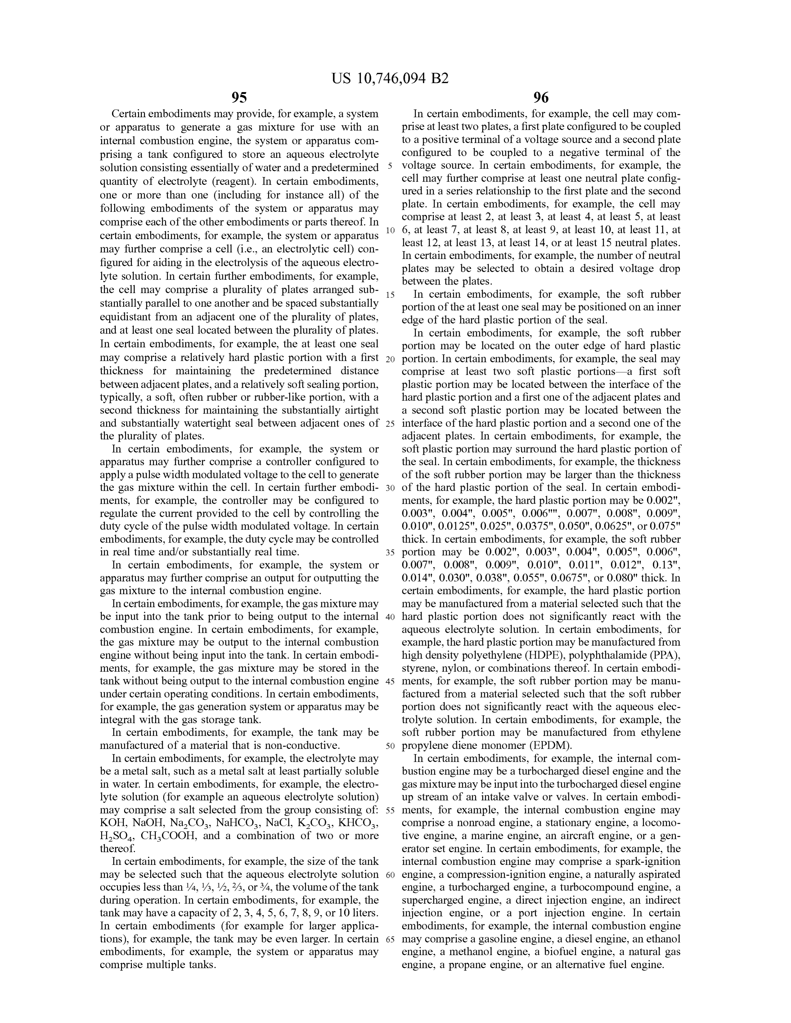
Page 64
In certain embodiments, for example, apparatus, methods, hydroxide radical, peroxide radical, ionic peroxide, combi or systems may comprise a scrubber. In certain embodi nations of one or more of these and /or mixtures of the same. ments, for example, the scrubber may comprise a switch In certain embodiments , for example, the gas mixture may configured to sense excess liquid and /or moisture in the form be a gas mixture comprising at least hydrogen ions and of foam in the gas stream and shut - off the electrolysis 5 oxygen ions , or diatomic oxygen and diatomic hydrogen, or process to prevent the excess moisture from entering the oxygen ion and diatomic oxygen , etc. In certain embodi internal combustion engine, and / or the accumulation of the ments , for example, the oxygen -hydrogen gas mixture may gas mixture . In certain embodiments, for example, the be an oxygen -rich gas mixture, an oxygen -hydrogen gas apparatus , methods, or systems may be exclusive of a mixture , or a hydrogen -rich oxygen -hydrogen gas mixture. scrubber. For example, HHO gas may be generated and / or 10 In certain embodiments, for example, the gas mixture may stored at a temperature ( for example a temperature in the comprise approximately two parts hydrogen to one part range of 100-110 ° F. ) that avoids excess and /or moisture and oxygen ( for example a ratio of hydrogen to oxygen of 2 : 1 ) therefore makes a scrubber unnecessary . or less than 2 : 1 ( for example a ratio of hydrogen to oxygen Certain embodiments may provide, for example, HHO of less than 1.75 : 1 , less than 1.5 : 1 , less than 1.25 : 1 , less than gas that is generated and distributed moisture - free. Mois- 15 1 : 1 , less than 0.75 : 1 , or a ratio ofhydrogen to oxygen of less ture - free HHO gas includes HHO gas free of entrained water than 0.5 : 1 , etc. ). In certain embodiments, for example, the droplets wherein the HHO gas is saturated with water at a gas mixture produced may be modified before being deliv sufficiently low temperature (and /or high pressure) such that ered to the internal combustion engine. In certain embodi no water condenses from the HHO gas during distribution ments, for example, the gas mixture may be combined with from an electrolysis unit to an internal combustion engine. 20 an additive and / or the composition of the gas mixture may In certain embodiments, for example, the moisture - free be modified by adding or removing portions of the gas HHO gas may have no more than 0.062 g / cmº ( for example mixture. In certain embodiments, for example, an electroly no more than 0.06 g /cm ", no more than 0.05 g / cm ", or no sis process may generate a gas mixture having a hydrogen to more than 0.04 g / cmº) water. In certain embodiments, for oxygen ratio in the range of between 1.8 : 1 to 2.3 : 1 , for example, the moisture - free HHO gas may be saturated with 25 example a hydrogen to oxygen ratio of 2 :1 , and an apparatus, water at a temperature of no more than 120 ° F. ( for example system , or method may be capable of delivering a gas no more than 110 ° F. or no more than 100 ° F. ) at a pressure mixture having a hydrogen to oxygen ratio of less than 2 : 1 , in the range of 40-60 psig ( for example a pressure in the for example a ratio of 1.8 : 1 or less , 1.7 : 1 or less , 1.5 : 1 or range of 45-50 psig) . less , 1.3 : 1 or less , by removing, or recycling, a portion of the Certain embodiments may provide, for example, appara- 30 hydrogen from the gas mixture prior to delivery. Alterna tus, methods, or systems to realize a fuel economy increase tively, in certain embodiments , for example, the apparatus, of at least 1 % , for example at least 2 % , at least 5 % , at least system , or method may be capable of generating a 2 : 1 ratio 10%, least 15 %, least 20 % , at least 25 % , at least 30 % , of hydrogen to oxygen but some of the hydrogen or oxygen , at least 35 % , at least 40 % , at least 45 % , at least 50% , or for example oxygen , may be trapped in bubbles, and the more . In certain embodiments, for example, the fuel 35 apparatus, system , or method may be configured to enable economy increase may be in the range of between 1-50 % , the release of the trapped oxygen to effectively deliver more for example between 1-5 % , between 5-10% , between oxygen to the internal combustion engine. Certain embodi 5-25 % , between 7-12 % , between 10-20% , between 15-25 % , ments, for example , may comprise methods capable of between 20-25 % , between 20-30 % , between 20-50 % , producing a gas mixture that is approximately two parts between 30-35 % , between 30-38 % , between 40-50 % , 40 oxygen to one part hydrogen ( for example 2 : 1 ) or less than between 40-45 % , or between 44-50 % . 2 : 1 ( for example 1.75 : 1 , 1.5 : 1 , 1.25 : 1 , 1 : 1 , etc. ) . In certain Certain embodiments may provide, for example, appara embodiments, for example, an electrolysis process may tus , methods, or systems to improve the operation of an generate between an oxygen to hydrogen ratio in the range internal combustion engine. In certain embodiments, for of between 1.8 : 1 to 2.3 : 1 , for example a 2 : 1 ratio of oxygen example, the internal combustion engine may operate at a 45 to hydrogen and the apparatus, system , or method may be cooler temperature and / or may run cleaner. capable of delivering a gas mixture having an oxygen to Certain embodiments may provide, for example, appara hydrogen ratio of less than 2 : 1 , for example an oxygen to tus, methods, or systems to produce an oxygen -hydrogen gas hydrogen ratio of 1.8 : 1 or less , 1.7 : 1 or less , 1.5 : 1 or less , mixture, such as an oxygen - rich, oxygen -hydrogen gas 1.3 : 1 or less . In certain embodiments, for example, the mixture , or a hydrogen -rich oxygen -hydrogen gas mixture . 50 apparatus, system , or method may be capable of delivering In certain embodiments, one or more than one ( including fora gas mixture having an oxygen to hydrogen ratio of less instance all ) of the following embodiments of the system or than 3.5 : 1 , less than 3 : 1 , less than 2.75 : 1 , less than 2.5 : 1 apparatus may comprise each of the other embodiments or oxygen to hydrogen .
parts thereof. In certain embodiments, for example, the gas Certain embodiments may provide, for example, appara mixture may be a low temperature plasma . In certain 55 tus, methods, or systems to more reliably controlled gas embodiments , for example, the plasma may be a cleaner mixture generation process . In certain embodiments, for plasma than that produced by other systems and / or methods. example, the current provided for gas generation may be In certain embodiments, for example, the plasma may be an continually or continuously regulated or controlled , for oxygen rich plasma . In certain embodiments, for example, example, in real time ( or substantially real time ) , so a the gas mixture may be an oxygen -rich or a hydrogen - rich 60 predetermined quantity of gas is consistently produced . gas mixture . In certain embodiments , for example, the gas Certain embodiments may provide, for example, appara mixture may comprise at least one or more of the following: tus , methods, or systems to utilize a substantially closed aqueous electrolyte solution electrolysis components : mona loop method of electrolysis that recycles a water -reagent (or tomic oxygen, diatomic oxygen, monatomic hydrogen, water -electrolyte or aqueous electrolyte solution electrolysis diatomic hydrogen, hydrogen ions , oxygen ions , mononu- 65 component) mixture in an effort to reduce its consumption. clear oxygen , mononuclear, ozone, singlet oxygen, hydrox Certain embodiments may provide, for example , appara ide ions , hydronium ions , superoxide, hydrogen superoxide, tus , methods, or systems capable of altering combustion ( for
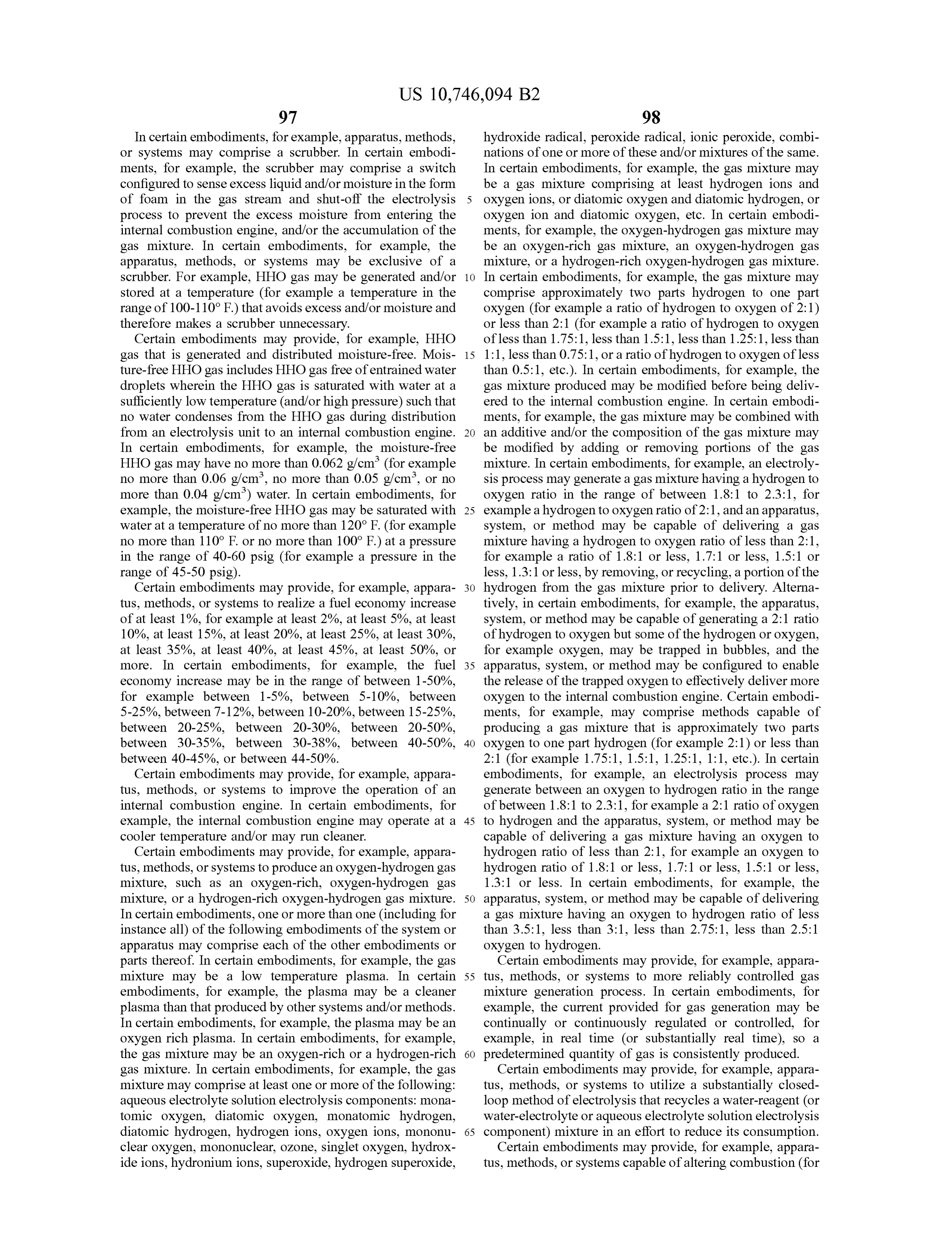
Page 65
example diesel combustion) chemistry to reduce particulate internal combustion engine during operation of the internal formation . In certain embodiments , for example, the meth combustion engine. In certain embodiments , for example, ods may be capable of achieving a reduction in particulate the gas mixture may be generated in substantially real time formation from an internal combustion engine of greater relative to the consumption of the gas mixture. In certain than 5 % , for example greater than 10 % , greater than 15 % , 5 embodiments, for example, the gas mixture may be gener greater than 20 % , greater than 25 % , greater than 30 % , ated onboard the vehicle during operation of the internal greater than 35 % , greater than 40 % , greater than 50 % , combustion engine.
greater than 60 % , greater than 75 % , greater than 80 % , Certain embodiments may provide, for example, appara greater than 90 % , greater than 95 % or close to 100 % . In tus, methods, or systems wherein a tank may be at least certain embodiments, for example, the concentration of an 10 oxidizer in an internal combustion engine may be increased . partially ing filled with an aqueous electrolyte solution consist essentially of water and a predetermined quantity of
In certain embodiments, for example, the increase in the electrolyte ( reagent ). In certain embodiments, for example, amount of oxidizers may be at least 5 % , for example at least the apparatus, methods , or systems may perform electrolysis 10 % , at least 15 % , at least 20 % , at least 25 % , at least 30 % , of the aqueous electrolyte solution within a cell (i.e. , an at least 35 % , at least 40 % , at least 45 % , or at least 50 % . In 15 certain embodiments, for example, the increase in the electrolytic cell) configured for aiding in the electrolysis of amount of oxidizers may be in the range of between 5-50 % , the aqueous electrolyte solution .
such as between 5-25 % , between 10-20 % , between 10-40 % , EXAMPLES
between 35-45 % , or between 40-50 % . Example 1 Certain embodiments may provide, for example, appara tus, methods, or systems to distribute the oxidizer for more A series of electrolysis cells were studied with different even air / fuel mixture . plates . In one cell , uncoated stainless steel plates were used Certain embodiments may provide, for example, appara- 25 and in a second cell platinum - coated stainless steel plates tus, methods, or systems to generate a gas mixture that is an were used . The electrolyte concentration , of potassium car accelerant to speed combustion and / or increase combustion bonate in water, was adjusted in the cell with uncoated plates completion. such that the current draw was essentially identical. All other Certain embodiments may provide, for example, appara conditions were essentially identical. The following table tus, methods, or systems to displace air with oxygen and /or 30 reports the results.
hydrogen within the engine's intake system .
Certain embodiments may provide, for example, appara TABLE 1 tus, methods, or systems to create a shorter combustion process that lowers the engine temperature thereby reducing Performance Feature Uncoated versus Coated Plates
Electrolyte Uncoated plates required approximately 3 times
Certain embodiments may provide, for example, appara Concentration greater concentration . tus , methods, or systems to generate an optimized or par HHO Gas Uncoated plates produced approximately 50 % less tially optimized quantity of a gas mixture, such as a gas Production HHO gas. After 4 hours of testing , the cells with uncoated mixture having one or more aqueous electrolyte solution Current Draw plates had a noticeably lower electrolyte level electrolysis components, into the engine's intake for 40 resulting in lower current draw . improved combustion . In certain embodiments , for example, the apparatus, methods, or systems may be capable of Experimental Note : Iridium- coated plates performed similar to platinum coated plates producing in the range of between 1-7.5 liters of gas per minute , such as 1.2 , 1.7 , 2.0 , 2.9 , 3.5 , 5.0 , or 7.0 liters of gas Example 2 per minute, and / or produce in the range of between 0.08- 45 0.75 liters of gas per minute per liter of engine displacement, A series of electrolysis cells were studied with different such as 0.1 , 0.12 , 0.17 , 0.20 , 0.25 , 0.29 , 0.3 , 0.32 , 0.35 , 0.4 , plates . In a first cell , 7 platinum coated stainless steel plates 0.45 , 0.50 , 0.6 , or 0.70 liters of gas per minute per liter of engine displacement. In certain embodiments, for example, were used and in a second cell 5 platinum coated stainless steel plates were used . The current draw was kept essentially the apparatus, methods, or systems may be capable of 50 the producing in the range of between 0.25-3 liters of gas per ing same the for both cells during the test procedure , by adjust concentration of the electrolyte in the 7 -plate cell to minute , such as between 0.25-2.5 , between 0.25-2 , between almost twice the concentration of the 5 -plate cell . All other 0.25-1.5 , between 0.25-1 , between 0.25-0.50 , between 0.50 conditions were essentially identical . The following table
between 1-2 , between 1-3 , between 1-1.5 , between 1.25- 55 reports the results.
1.75 , between 1.5-2 , between 2-2.5 , between 2.5-3 liters of TABLE 2 gas per minute.
Certain embodiments may provide, for example, appara Performance Feature 5 Plates Versus 7 Plates tus, methods, or systems to reduce the particulate emissions HHO Gas Production 5 plates produced 20-25 % more HHO gas . of an internal combustion engine. In certain embodiments, 60 for example, a method may comprise the steps of generating a gas mixture for use within the internal combustion engine and providing the gas mixture to the internal combustion Example 3 engine during operation of the internal combustion engine.
In certain embodiments , for example, a method may com- 65 A series of experiments was conducted with and without prise: generating a gas mixture for use within the internal HHO gas injection . In the experimental setup , a vehicle combustion engine, and providing the gas mixture to the powered by a PACCAR MX - 13 diesel engine underwent
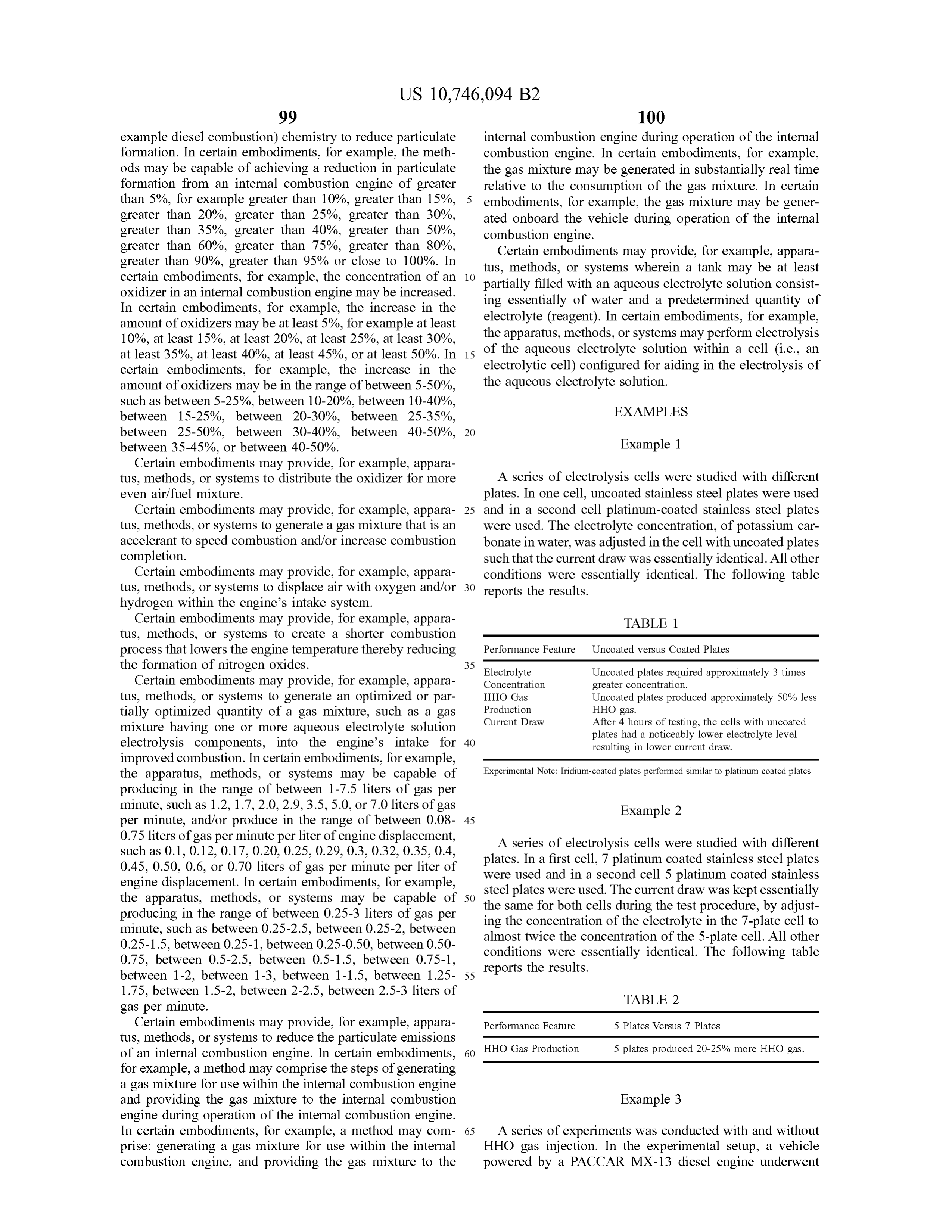
Page 66
snap acceleration from 0 to 80 mph in a chassis dynamom addition , any combination of two or more such features , eter test cell and exhaust emissions measured . Results are systems , articles, materials, and / or methods, if such features, recorded in Table 3 . systems , articles, materials , and/ or methods are not mutually inconsistent, is included within the scope of the present
The indefinite articles " a " and " an ,” as used herein in the
Emissions Reduction ( results in PPM ) when HHO specification and in the claims , unless clearly indicated to Gas Injected Into PACCAR MX - 13 Diesel Engine .
the contrary, should be understood to mean “ at least one . "
Exhaust Component With HHO Injection Without HHO Injection The phrase " and / or, ” as used herein in the specification
NOX 40 295 and in the claims , should be understood to mean “ both or
either or in a series having more than two elements all or a
HC 0 0 subset of all elements or just one of the elements” Thus, as 02 8.9 8.6 a non - limiting example, a reference to " A , B and / or C ,” is 15 understood to include A , B and C , A and B , A and C , B and
C , and A or B or C. As used herein in the specification and
Example 4 in the claims , the phrase “ at least one,” in reference to a list of one or more elements , should be understood to mean at
A series of experiments was conducted with and without least one element selected from any one or more of the HHO gas injection. In the experimental setup , a vehicle 20 elements in the listof elements, but not necessarily including at least one of each and every element specifically listed powered by a PACCAR MX - 13 diesel engine was run at a within steady state speed of 60 mph for 5 minutes in a chassis tions oftheelements list of elements and not excluding any combina in the list of elements . This definition also dynamometer test cell , and fuel economy and exhaust emis allows that elements may optionally be present other than sions measured . The experiment was repeated without HHO 25 the elements specifically identified within the list of ele gas injection . Results are recorded in Table 4 . ments to which the phrase “ at least one” refers, whether
TABLE 4
related or unrelated to those elements specifically identified .
Thus, as a non -limiting example, “ at least one of A and B ”
Increased Fuel Economy and Emissions Reduction (results in ( or, equivalently, “ at least one of A or B ,” or, equivalently “ at PPM ) when HHO Gas Injected Into PACCAR MX -13 Diesel Engine. 30 least one of A and / or B ” ) can refer, in one embodiment, to at least one , optionally including more than one , A , with no
With HHO Injection Without HHO Injection B present (and optionally including elements other than B ) ; Fuel Economy (GPH ) 6.46 7.73 in another embodiment, to at least one, optionally including NOX
more than one , B , with no A present and optionally includ
35 ing elements other than A ) ; in yet another embodiment, to at
HC 0 1 least one, optionally including more than one , A , and at least 02 14.5 14.2 one , optionally including more than one , B ( and optionally including other elements ); etc.
In the claims
All publications and patent applications mentioned in this 40 transitional , assuch phrases wellasas“in the specification comprising above ," " including,” “ , car all specification are herein incorporated by reference to the rying, " " having, " " containing , " “ involving , " " holding, " and same extent as if each individual publication or patent the like are to be understood to be open - ended , i.e. , to mean application was specifically and individually indicated to be including but not limited to . Only the transitional phrases incorporated by reference. " consisting of" and " consisting essentially of " shall be While several embodiments of the present invention have 45 closed or semi - closed transitional phrases, respectively, as been described and illustrated herein , those of ordinary skill set forth in the United States Patent Office Manual of Patent in the art will readily envision a variety of other means Examining Procedures , Section 2111.03 .
and / or structures for performing the functions and / or obtain The features disclosed in this specification ( including ing the results and / or one or more of the advantages accompanying claims , abstract, and drawings ) may be described herein , and each of such variations and / or modi- 50 replaced by alternative features serving the same , equivalent fications is deemed to be within the scope of the present or similar purpose , unless expressly stated otherwise. Thus, invention . More generally, those skilled in the art will unless expressly stated otherwise , each feature disclosed is readily appreciate that all parameters , dimensions , materials, one example of a generic series of equivalent or similar and configurations described herein are meant to be exem features.
plary and that the actual parameters, dimensions , materials , 55 The subject headings used in the detailed description are and /or configurations will depend upon the specific appli included for the ease of reference of the reader and should cation or applications for which the teachings of the present not be used to limit the subject matter found throughout the invention is/ are used . Those skilled in the art will recognize, disclosure or the claims . The subject headings should not be or be able to ascertain using no more than routine experi used in construing the scope of the claims or the claim mentation, many equivalents to the specific embodiments 60 limitations.
the invention described herein . It is , therefore, to be under The disclosure has been described with reference to stood that the foregoing embodiments are presented by way particular embodiments. However, it will be readily appar of example only and that, within the scope of the appended ent to those skilled in the art that it is possible to embody the claims and equivalents thereto , the invention may be prac disclosure in specific forms other than those of the embodi ticed otherwise than as specifically described and claimed . 65 ments described above . The embodiments are merely illus The present invention is directed to each individual feature, trative and should not be considered restrictive . The scope of system , article, material, and / or method described herein . In the disclosure is given by the appended claims , rather than
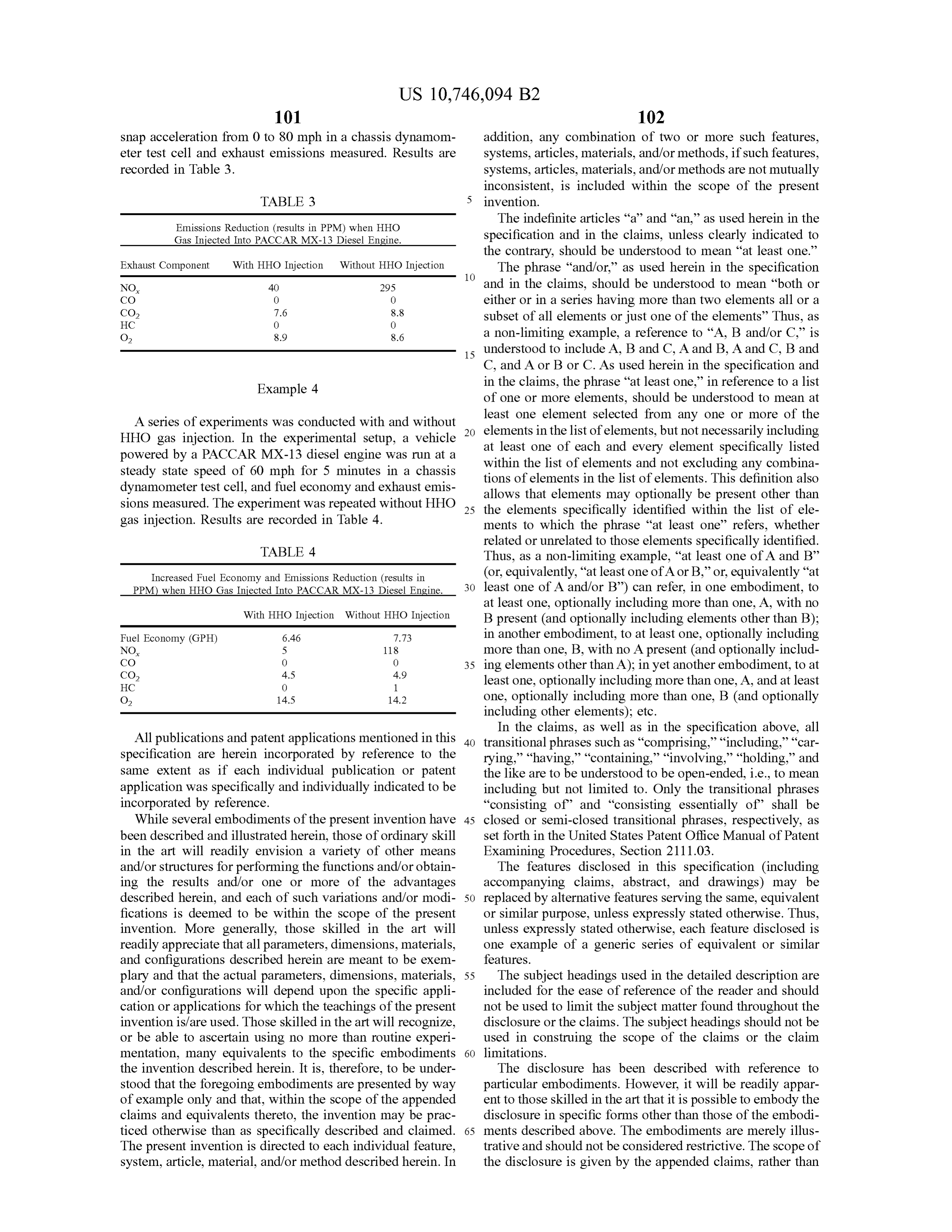
Page 67
the preceding description, and all variations and equivalents 14. The onboard HHO generator of claim 12 , wherein the that fall within the range of the claims are intended to be controller is configured to control the power supply to embraced therein . maintain the second chamber at a pressure of between 45 What is claimed is : psig and 50 psig .
1. An onboard HHO generator for an over - the - road truck 5 15. The onboard HHO generator of claim 12 , wherein the powered by a diesel engine, comprising: controller is configured to operate the electrolysis cell to a dual - chamber vessel in communication with the diesel maintain a temperature of the quantity of the electrolyte engine, comprising:
i . an electrolysis cell in a first chamber of the dual solution and a pressure in the second chamber. chamber vessel , the first chamber containing a quan- 10 maintainedonboard 16. The HHO generator of claim 15 , wherein the pressure is between 45 psig and 50 psig .
tity of electrolyte solution and a plurality of elec 17. The onboard HHO generator of claim 1 , wherein the trodes, the quantity of electrolyte solution sufficient second chamber is cooperatively configured with the first to produce a supply of HHO gas for 60,000,000 chamber to receive the supply of HHO gas from the first crankshaft rotations of the diesel engine; and ii . a second chamber containing HHO gas and a quan- 15 chamber
and to contain a portion of the supply of HHO gas .
onboard HHO generator of claim 1 , wherein the tity of replacement electrolyte solution , the con second chamber is configured to contain 30 minute supply of tained HHO gas and the quantity of replacement HHO gas for use by the diesel engine based on an average electrolyte solution sharing a free surface , the first load of 200 hp, the diesel engine having a displacement chamber and the second chamber in continuous liquid communication, the second chamber disposed 20 between 10 liters and 24 liters.
19. The onboard HHO generator of claim 1 , wherein a between the first chamber and the diesel engine, total volume of the first chamber is less than or equal to a wherein the plurality of electrodes are fully immersed in total volume of the second chamber. the quantity of electrolyte solution throughout all ori 20. The onboard HHO generator of claim 1 , wherein the entations of the dual -chamber vessel .
2. The onboard HHO generator of claim 1 , which is in 25 21.chamber first
The is cooled by engine coolant.
onboard HHO generator of claim 1 , wherein the communication with at least one combustion chamber of the diesel engine, the diesel engine having between 6 combus the plurality of electrodes comprise iridium coated on tita nium .
tion chambers and 20 combustion chambers.
3. The onboard HHO generator of claim 2 , wherein the 22. The onboard HHO generator of claim 1 , wherein the diesel engine has a displacement of between 11 liters and 16 30 tion supplyof oftheHHO gas is sufficient for 10,000 miles of opera truck .
liters .
23. The onboard HHO generator of claim 1 , which is in 4. The onboard HHO generator of claim 2 , wherein the communication diesel engine can operate at an engine speed of between deliver at least a with an injector, the injector configured to portion of the supply of HHO gas to a diesel
5. The onboard HHO generator of claim 2 , wherein the 35 particulate filter ( DPF ) regenerator system . 24. The onboard HHO generator of claim 1 , which is in diesel engine provides a peak torque of between 1600 ft - lb communication with a plurality of injectors, the plurality of
6. The onboard HHO generator of claim 2 , wherein the injectors configured to introduce at least a portion of the supply of HHO gas to at least one combustion chamber inlet diesel engine can produce between 400 hp and 700 hp.
7. The onboard HHO generator of claim 2, wherein a first 40 of the diesel engine. , the diesel engine having in the range of injector is configured to deliver at least a portion of the 6 to25.20Thecylinders supply of HHO gas during a portion of an intake stroke of plurality ofonboard injectors
HHO generator of claim 24 , wherein the comprises :
a first combustion cylinder of the diesel engine, the first i ) a first injector configured to deliver a first portion of the combustion cylinder comprising a first combustion chamber supply of HHO gas to within 3 inches of a first of the at least one combustion chamber. 45 combustion chamber inlet of the diesel engine;
8. The onboard HHO generator of claim 7 , wherein the ii ) a second injector configured to deliver a second portion during a portion of an intake stroke is when the intake stroke of the supply of HHO gas to a second combustion is at an angle of between 0 ° and 40 ° from top -dead -center. chamber inlet of the diesel engine; and 9. The onboard HHO generator of claim 1 , wherein the iii ) a third injector configured to deliver a third portion of over -the - road truck is a Class 8 vehicle . 50 the supply of HHO gas to a third combustion chamber 10. The onboard HHO generator of claim 1 , wherein the inlet of the diesel engine. quantity of electrolyte solution is sufficient for 30,000 miles 26. The onboard HHO generator of claim 1 , which is in of driving.
11. The onboard HHO generator of claim 1 , wherein the communication with a heat exchanger, the heat exchanger first chamber is configured to contain 1 gallon of the 55 configured to receive at least a portion of the supply of HHO gas .
electrolyte solution .
12. The onboard HHO generator of claim 1 , further heat27.exchanger
The onboard HHO generator of claim 26 , wherein the comprising a controller, the controller configured to control stream and / or anis engine configured to receive an engine exhaust coolant stream .
a power supply to the electrolysis cell . 28. The onboard HHO generator of claim 1 , wherein the 13. The onboard HHO generator of claim 12 , wherein the 60 supply of HHO gas is sufficient for 60,000,000 crankshaft controller is configured to control the power supply to rotations of the diesel engine at an average load of 200 hp . maintain the quantity of the electrolyte solution at a tem perature of between 100 ° F. and 110 ° F.
Provenance
- Collection
- Patents citing this work
- Original assignee
- Hytech Power LLC
- Pages
- 67
- Method
- pdftotext (the PDF's own text layer) + pdftoppm 300dpi page scans
- Patent office record
- patents.google.com →
- Source
- Google Patents citing-documents table
- Inventors
- Evan Charles Johnson; William A. Woods; Hytech Power LLC
- Published
- 2020-08-18
- Transcribed from
- patentimages.storage.googleapis.com →