patent · US4761958
Fuel lance for the combustion chamber of a gas turbine
9 August 1988
Page 1 — bibliographic record
United States Patent (19) (11 Patent Number: 4,761,958 Hellat 45 Date of Patent: Aug. 9, 1988 54 FUEL LANCE FOR THE COMBUSTION 3,234,731 2/1966 Dermody et al. .................... 60/741 CHAMBER OF A GASTURBINE 3,664,124 5/1972 Fehler ......... ... 60/741
(75) Inventor: Jaan Hellat, Baden-Riitihof, 3,726,088 4/1973 Kretschmer et al. ................. 60/741 Switzerland Primary Examiner-Carlton R. Croyle 73 Assignee: BBC Brown, Boveri & Company, Assistant Examiner-Timothy S. Thorpe Ltd., Baden, Switzerland Attorney, Agent, or Firm-Burns, Doane, Swecker & Mathis (21) Appl. No.: 802,604 57 ABSTRACT
Self-excited vibrations can occur in the combustion
Related U.S. Application Data chambers of gas turbines, which vibrations are due to modulation of the quantity of gaseous fuel or fuel/air 63 Continuation of Ser. No. 596,607, Apr. 4, 1984, aban mixture as the fuel is injected through a nozzle and into doned. the combustion chamber. The modulation results from 30 Foreign Application Priority Data pressure fluctuations that occur in the plane of the noz Apr. 13, 1983 ICH Switzerland ......................... 1988/83 zle. The new fuel lance simultaneously permits both de-coupling of the fuel line in order to avoid combus 51) Int. Cl." ................................................ FO2C 1/00 tion chamber vibrations and the possibility of fuel quan 52 U.S. C. ...................................................... 60/737 tity control. The fuel lance comprises an adjustable 58 Field of Search ................. 60/737, 740, 741, 738, throttle body that is provided with fuel passage open 60/742, 749 ings and a plunger, the penetration depth of which (56) References Cited plunger relative to that of the throttle body is a measure of the fuel quantity flowing therethrough.
2,775,484 12/1956 Fox ....................................... 60/741 4. Claims, 1 Drawing Sheet
NYNYYNNNNN N N ANN NNNNNY NNNNN
ZZZZZZZZZZZZZZZZZIZIZZZZZZZ
N star N N N N N INNAN NNN N N Ya N N N N N N N N
Page 2
Drawing sheet — no readable text.
Page 3
In the case of a supply of premixed fuel, an additional
FUEL LANCE FOR THE COMBUSTION advantage of the present invention lies in the fact that CHAMBER OF A GASTURBNE the throttle body simultaneously acts as a flame trap. Embodiment examples of the subject matter of the
This application is a continuation of application Ser. 5 invention are shown in simplified form and explained in No. 596,607, filed Apr. 4, 1984 now abandoned. more detail below using the accompanying drawings. Those elements which are not required in order to ob
BACKGROUND AND SUMMARY OF THE tain an understanding of the invention are not depicted.
INVENTION
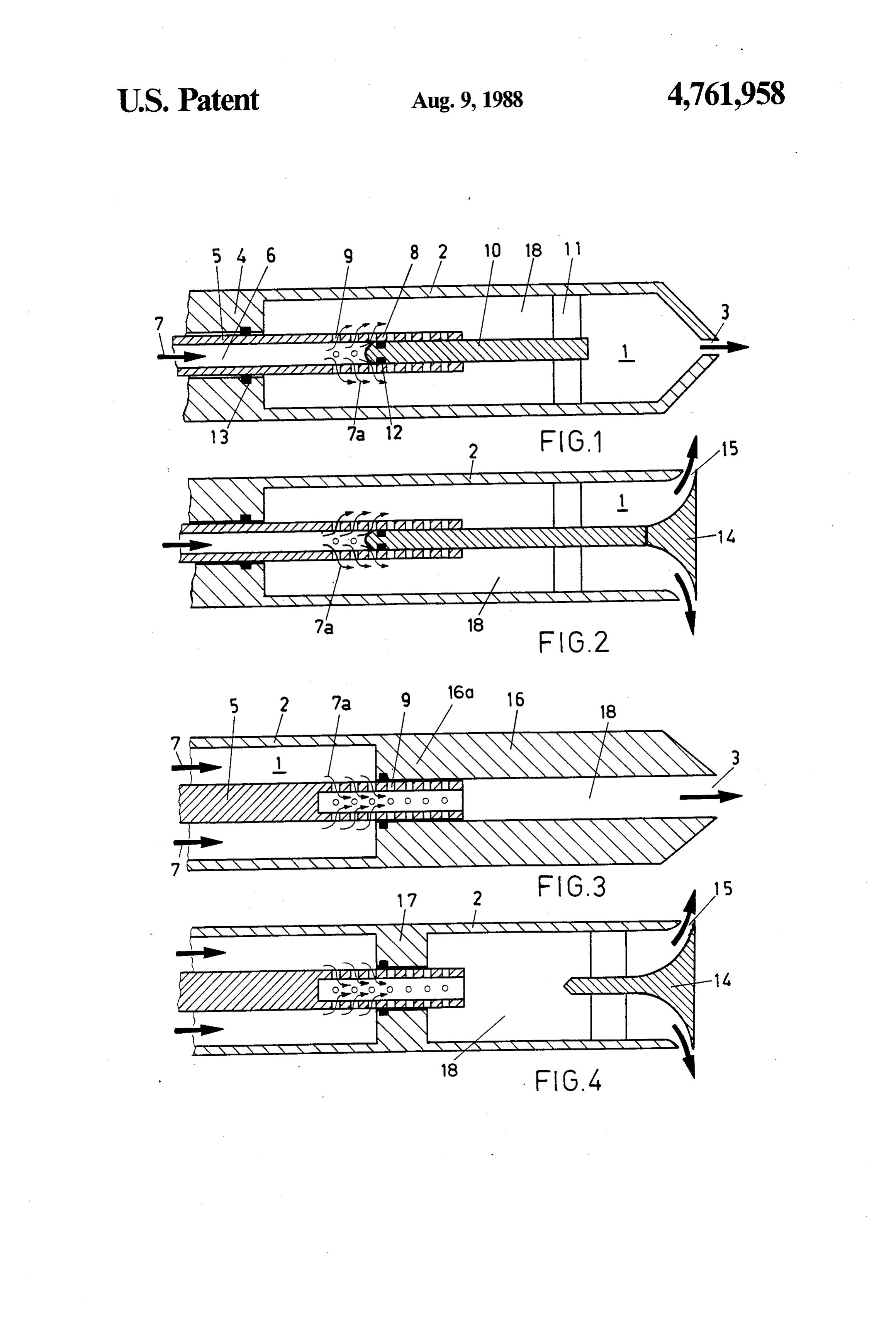
BRIEF DESCRIPTION OF THE DRAWINGS
Self-excited vibrations can occur in combustion 10 chambers. These vibrations are due to a modulation of FIG. 1 shows a fuel lance with fuel supply through an the quantity of gaseous fuel or fuel/air mixture injected inner pipe and a central nozzle outlet; into the combustion chamber through a nozzle, the inner FIG. 2 shows a fuel lance with fuel supply through an modulation being caused by pressure fluctuations in the pipe and a radial nozzle outlet; plane of the nozzle. The feedback circuit necessary for 15 theFIG. 3 shows a fuel lance with fuel supply through lance pipe and a central nozzle outlet;
self-excitation is closed whenever the changes in the fuel consumption in the flame caused by the supply theFIG. 4 shows a fuel lance with fuel supply through lance pipe and a radial nozzle outlet.
fluctuations satisfy a phase condition with the chamber pressure. A classical example of this is the so-called 20 DETALED DESCRIPTION OF THE "singing flame'. INVENTION
Such vibrations can be dealt with, essentially, in two FIG. 1 shows, in a simplified manner, the concept of ways:
1. By modification of the acoustic properties, i.e., of burner,lance a fuel 1, which lance is a constituent part of a the impedances of the fuel supply or the chamber. 25 part of a combustionwhich not shown, burner in turn is a constituent chamber, again not shown, of, for
These measures, however, are only effective within a example, a gas turbine. The burner certain frequency band, as the impedances depend upon a diffusion burner with swirled airmay, for example, be supply.
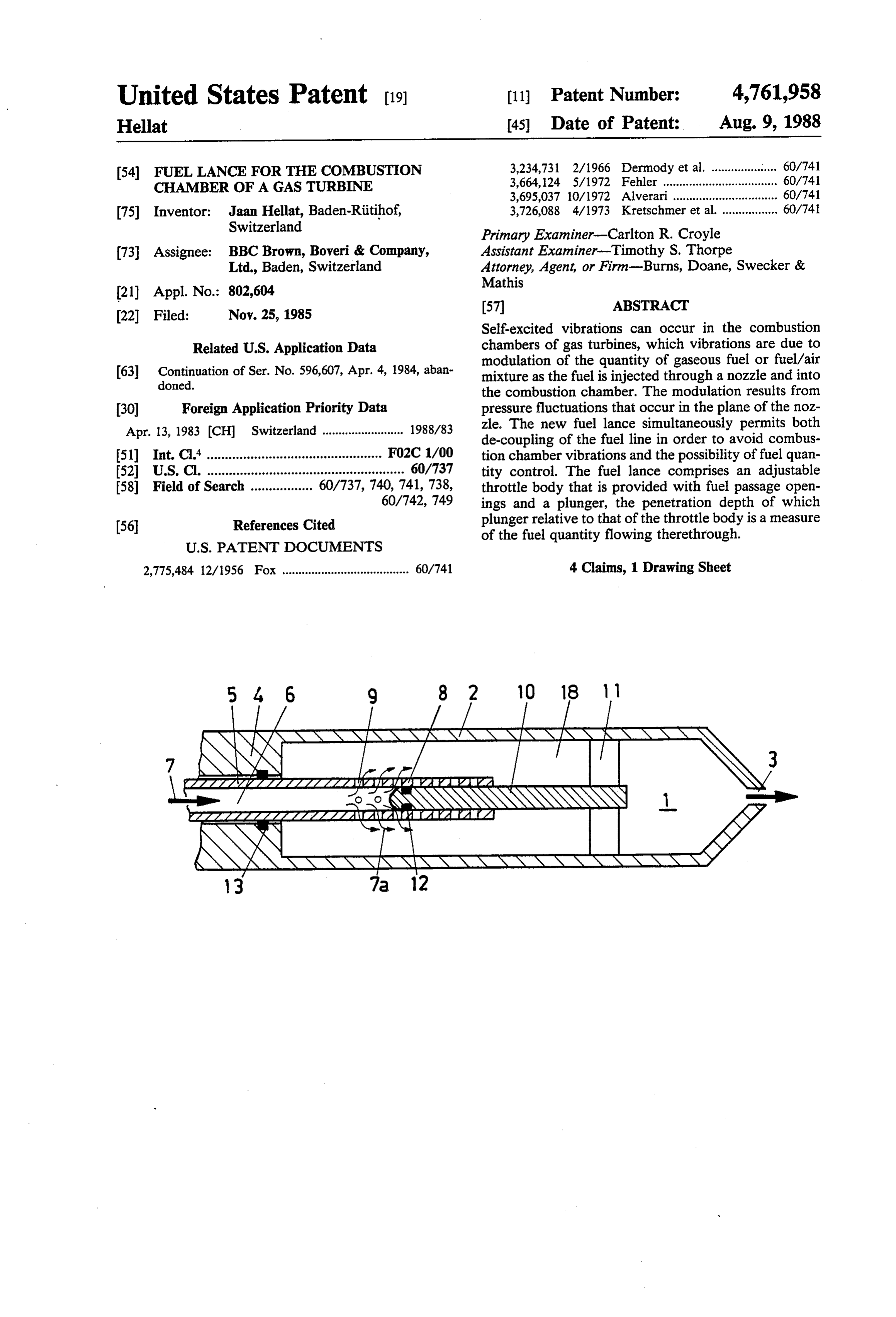
the frequency. The fuel lance 1 consists of a lance pipe 2 with a 2. By acoustic decoupling of the fuel supply system central nozzle outlet 3. Upstream of the lance pipe 2, the through the use of an infinitely large inlet impedance. 30 fuel lance 1 is formed by a bush 4, in which is guided an This impedance is attained by means of strong throttling axially adjustable tubular throttle body 5. Fuel 7 is sup of the fuel supply in the vicinity of the combustion plied through the inside of a pipe 6. On the downstream chamber inlet, as provided for example, by sonic noz side of the fuel lance, the pipe wall 8 in the unguided zles. This assumes that the fuel is supplied with a suffi part of the throttle body 5 is provided with fuel passage ciently high pressure, which is actually the case, or may 35 openings 9 in the peripheral and in the axial direction. be achieved in most cases. This measure acts indepen Both the number and the arrangement of the fuel pas dent of frequency; However, the application of this sage opening is arbitrary; as far as the shape is con procedure does not make it possible to vary the fuel cerned, holes or slots may, for example, be provided. As quantity over a wide range. A conventional control far as the number and size of the fuel passage openings valve, which provides throttling and quantity adjust 9 is concerned, this depends on the maximum through ment, can only be applied outside of the total burner put required for the particular burner. A nozzle channel system in burners of conventional type. In this case, 18 directs the fuel from the openings 9 to the nozzle however, there still remains a supply system between outlet 3. The lance pipe 2 carries a plunger 10 inside the the control valve and the combustion chamber inlet pipe 6, which plunger 10 is centrally supported within and, under certain circumstances, this supply system 45 the pipe 6 of the throttle body 5 by means of struts 11, may participate in a vibration. as struts are conventionally used for supporting internal The objective of the invention is to produce a burner bodies in cross-sections through which a fluid flow which combines in itself the decoupling, described passes. A seal 12 also placed in this location ensures that above, of the fuel supply line in order to avoid combus the fuel passage openings 9 positioned over the plunger tion chamber vibrations with the possibility of control 50 10 for the given axial position of the throttle body 5 are ling the quantity of fuel. closed in a gas-tight manner. A gas-tight seal between In accordance with the invention, this objective is the throttle body 5 and the bush 4 is provided by a seal achieved by means of a fuel lance of the type mentioned 13. The free cross-section, such as the number of fuel at the beginning having the characterising above. passage openings 9 still being used, and, therefore, the The advantage of the invention is substantially to be 55 fuel quantity 7a flowing through the fuel passage open seen in that a fuel lance is produced in a relatively sim ings may be varied by axial displacement of the throttle ple manner, which fuel lance combines in itself in a body 5 relative to the plunger 10. The free flow cross compact manner both a decoupling of the fuel line in section therefore depends upon the penetration depth of order to avoid combustion chamber vibrations and the the plunger 10 relative to the throttle body 5 at any possibility of fuel quantity control. given time. If the ratio between the fuel pressure in the The decoupling is effective by virtue of the compact supply line and the pressure at the nozzle outlet 3 ex construction of the fuel lance, the distance between the ceeds a critical value, the fuel 7 flows through the fuel throttle body and the nozzle outlet may be kept substan passage openings 9 of the throttle body 5 with sonic tially shorter than the wavelength of typical natural velocity such that pressure disturbances passing up vibrations of the combustion chamber system. 65 stream from the nozzle outlet 3 no longer will influence A further advantage of the invention is that the fuel the fuel quantity 7a emerging from the fuel passage lance may be provided with a central or radial nozzle openings 9. With respect to design of the fuel lance, it is outlet. important to ensure that the distance between the fuel
Page 4
passage openings 9 and the nozzle outlet 3 or 15 is sub a tubular throttle body, means mounting said throttle stantially shorter than the wavelength of typical natural body in said lance pipe for axial movement relative vibrations of the combustion chamber system. to said pipe, said body extending into said interior FIG. 2, like FIG. 1, also shows a simplified represen chamber, a source of gaseous fuel and means for tation of a fuel lance 1. This embodiment is character conducting gaseous fuel from said source to the ised by the difference, relative to FIG. 1, of fuel flow in interior of said throttle body, said plunger being that the fuel quantity 7a flowing from the fuel lance 1 received in said tubular body and said throttle body now emerges radially. The lance pipe 2 remains cylin having a plurality of fuel openings spaced longitu drical and open on the nozzle outlet side. The plunger dinally along said body in said chamber through 10 is extended beyond the struts 11 and carries on its end O which gaseous fuel passes from the interior of said a central body 14. The opening between the end of the throttle body into said chamber, said plunger in lance pipe 2 and the inner, outwardly-curved portion of cluding means for progressively closing off prede the central body 14 forms a radial nozzle outlet 15. termined members of said plurality of fuel openings In FIG. 3, the fuel 7 is supplied directly through the according to the relative longitudinal position of fuel lance 1. The lance pipe 2 changes downstream into 15 said throttle body relative to said plunger, the lon a bush 16 that extends as far as the central nozzle outlet gitudinal position of said throttle body regulating 3. The throttle body 5 is a spindle which has a tubular the quantity of fuel passing into said combustion recess or bore at one end only and only over a certain chamber while limiting the position of any fuel length. The fuel passage openings 9 are also located in opening relative to said nozzle outlet to a predeter this part. The inner diameter of the bush 16 also forms 20 mined distance that is less than the wavelength of the nozzle channel 18 to the central nozzle outlet 3 and the natural vibration of the combustion chamber includes a bush portion 16a which receives the throttle system.
body 5. The free cross-section, i.e., the number of fuel 2. The fuel lance as claimed in claim 1, wherein said passage openings 9 still in use, and, therefore, the fuel means supporting said plunger includes struts extending quantity 7a flowing therethrough may be altered by 25 radially from said plunger to said lance pipe, said throt axial displacement of the throttle body 5 relative to the tle body sliding over said plunger, said means mounting bush 16. The fuel 7 flows around the throttle body 5 in said throttle body in said lance pipe including a bush at the region of the lance pipe portion 2. At the point of the other end of said interior chamber and a seal posi the throttle body 5 where the lance pipe 2 becomes the tioned between said bush and said throttle body. bush 16, the fuel flows through those fuel passage open 30 3. A fuel lance for supplying gaseous fuel to a com ings 9 which, because of the fuel quantity control, are bustion chamber of a gas turbine without interference still in use, i.e., those fuel passage openings which have from a natural vibration of said combustion chamber, not yet been enveloped by the bush 16. In contrast to said sonic fuel lance comprising:
FIGS. 1 and 2, the fuel 7, in this case, flows along the a lance pipe having an interior chamber with a nozzle exterior of the throttle body, into the interior of the 35 outlet adjacent one end of said chamber; throttle body and passes therefrom to the nozzle outlet a source of gaseous fuel; and 3 a tubular throttle body, means mounting said throttle FIG. 4 shows a lance pipe 2 open on both sides, body in said lance pipe for axial movement relative which lance pipe is divided by a throat 17 in the center. to said pipe, said body extending into said interior The throat performs the same function as that of the chamber, passage means in said lance pipe to con bush portion 16a, described in the discussion of FIG. 3 duct gaseous fuel from said source to the exterior above. The central body 14 makes possible a radial of said throttle body, said throttle body having a nozzle outlet 15 through which fuel passes, as discussed plurality of fuel openings spaced longitudinally with the description of FIG. 2 above. along said body, sealing means in said chamber It is to be understood that the present invention may 45 spaced from said nozzle outlet for progressively be embodied in other specific forms without departing closing off predetermined members of said plural from the spirit or essential characteristics of the present ity of fuel openings according to the relative longi invention. The preferred embodiments are therefore to tudinal position of said throttle body relative to be considered illustrative and not restrictive. The scope said nozzle outlet, the longitudinal position of said of the invention is indicated by the appended claims 50 throggle body regulating the quantity of fuel pass rather than by the foregoing descriptions and all ing from the exterior of said throttle body into said changes or variations which fall within the meaning and combustion chamber while limiting the position of range of the claims are therefore intended to be em any fuel opening relative to said nozzle outlet to a braced therein. predetermined distance that is less than the wave What is claimed is: 55 length of the natural vibration of the combustion 1. A fuel lance for supplying gaseous fuel to a com chamber system.
bustion chamber of a gas turbine without interference 4. The fuel lance as claimed in claim 3, wherein said from a natural vibration of said combustion chamber, means for mounting said throttle body in said lance pipe said fuel lance comprising: includes a bush at the other end of said interior cham a lance pipe having an interior chamber with a nozzle 60 ber, said throttle body having a longitudinal bore open outlet adjacent one end of said chamber; to said interior chamber, said plurality of fuel openings a plunger in said interior chamber, means supporting communicating said passage means in said lance pipe said plunger at a fixed location spaced from said with said bore. - nozzle outlet;
Provenance
- Collection
- Cited prior art
- Original PDF
- patentimages.storage.googleapis.com →
- Filed
- 1985-11-25
- Pages
- 4
- Method
- pdftotext (the PDF's own text layer) + pdftoppm 300dpi page scans
- Source
- Google Patents bibliographic record
- Granted
- 1988-08-09
- Inventors
- Jaan Hellat; BBC Brown Boveri AG Switzerland
- Transcribed from
- patentimages.storage.googleapis.com →