patent · US4004554
Fuel converting method and apparatus
25 January 1977
Page 1 — bibliographic record
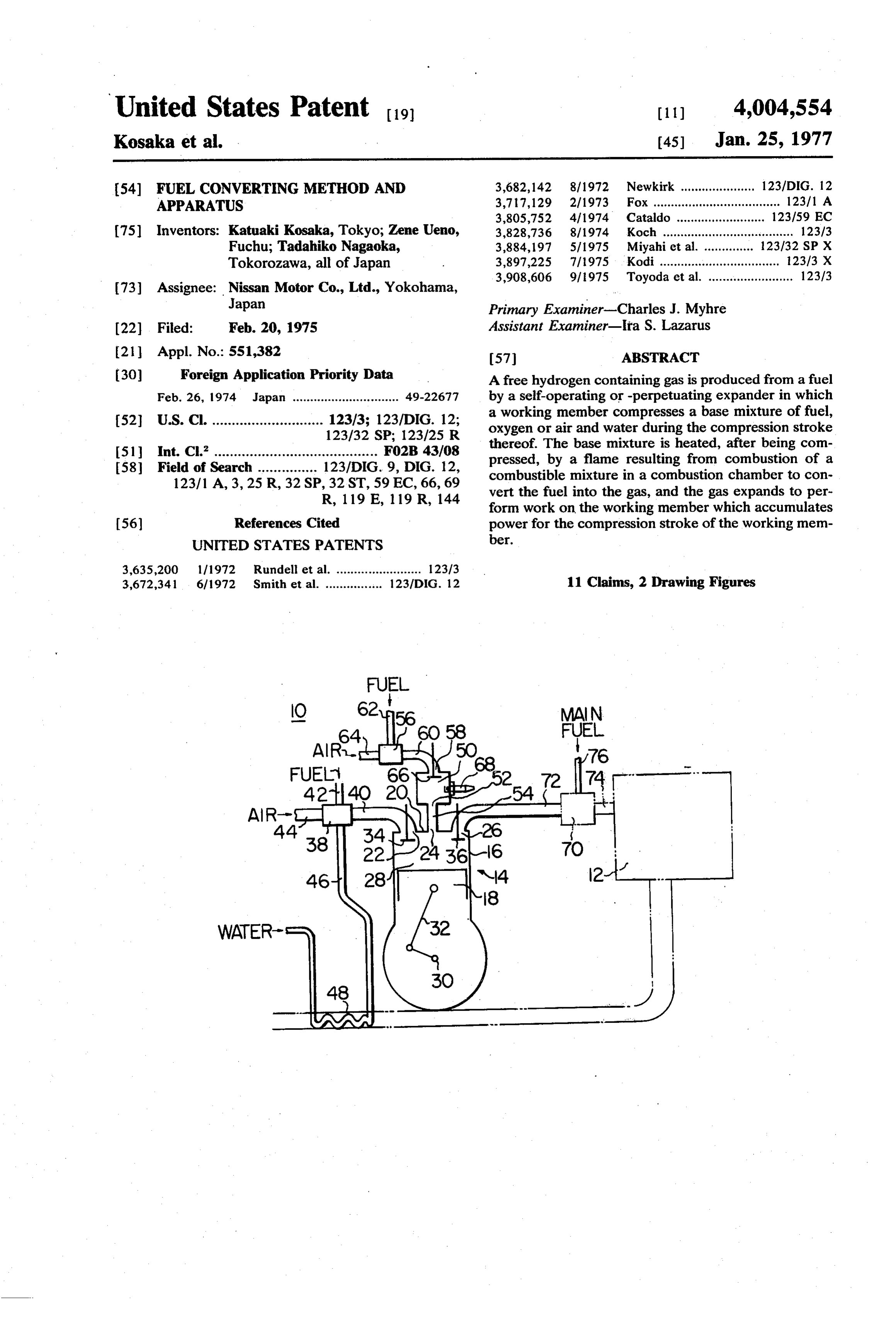
United States Patent to (11) 4,004,554 Kosaka et al. 45 Jan. 25, 1977 54) FUEL CONVERTING METHOD AND 3,682,142 8/1972 Newkirk ..................... 123/DIG. 12 APPARATUS 3,717, 129 2/1973 Fox .................................... 123/1 A 3,805,752 4/1974 Cataldo ..... ... 123/59 EC (75) Inventors: Katuaki Kosaka, Tokyo; Zene Ueno, 3,828,736 8/1974 Koch ..................................... 123/3 Fuchu; Tadahiko Nagaoka, 3,884,197 5/1975 Miyahi et al. .............. 123132 SP X Tokorozawa, all of Japan 3,897,225 7/1975 Kodi .................................. 123/3 X 3,908,606 9/1975 Toyoda et al. ........................ 123/3 73) Assignee: Nissan Motor Co., Ltd., Yokohama,
Japan Primary Examiner-Charles J. Myhre (22) Filed: Feb. 20, 1975 Assistant Examiner-Ira S. Lazarus 2 Appl. No.: 551.382 57 ABSTRACT 30 Foreign Application Priority Data A free hydrogen containing gas is produced from a fuel Feb. 26, 1974 Japan .............................. 49.22677 by a self-operating or -perpetuating expander in which 52 U.S. C. ............................ 123/3; 123/DIG. 12; a working member compresses a base mixture of fuel, 123/32 SP; 123/25 R oxygen or air and water during the compression stroke 51 int. Cl. ......................................... F02B 43/08 thereof. The base mixture is heated, after being com 58 Field of Search ............... 123/DIG. 9, DIG. 12, pressed, by a flame resulting from combustion of a combustible mixture in a combustion chamber to con 123/1 A, 3, 25 R, 32 SP, 32 ST, 59 EC, 66, 69 vert the fuel into the gas, and the gas expands to per R, 1 19 E, 119 R, 144 form work on the working member which accumulates (56) References Cited power for the compression stroke of the working mem UNITED STATES PATENTS ber.
3,635,200 111972 Rundell et al. ........................ 123/3 3,672,341 6/1972 Smith et al. ................ 123/DIG. 12 11 Claims, 2 Drawing Figures
Page 2
Drawing sheet — no readable text.
Page 3
to heat the same to a high temperature necessary to
FUEL CONVERTING METHOD AND APPARATUS accomplish fuel converting reaction, and so make it unnecessary to adiabatically compress the base mix
The present invention relates generally to a method ture.
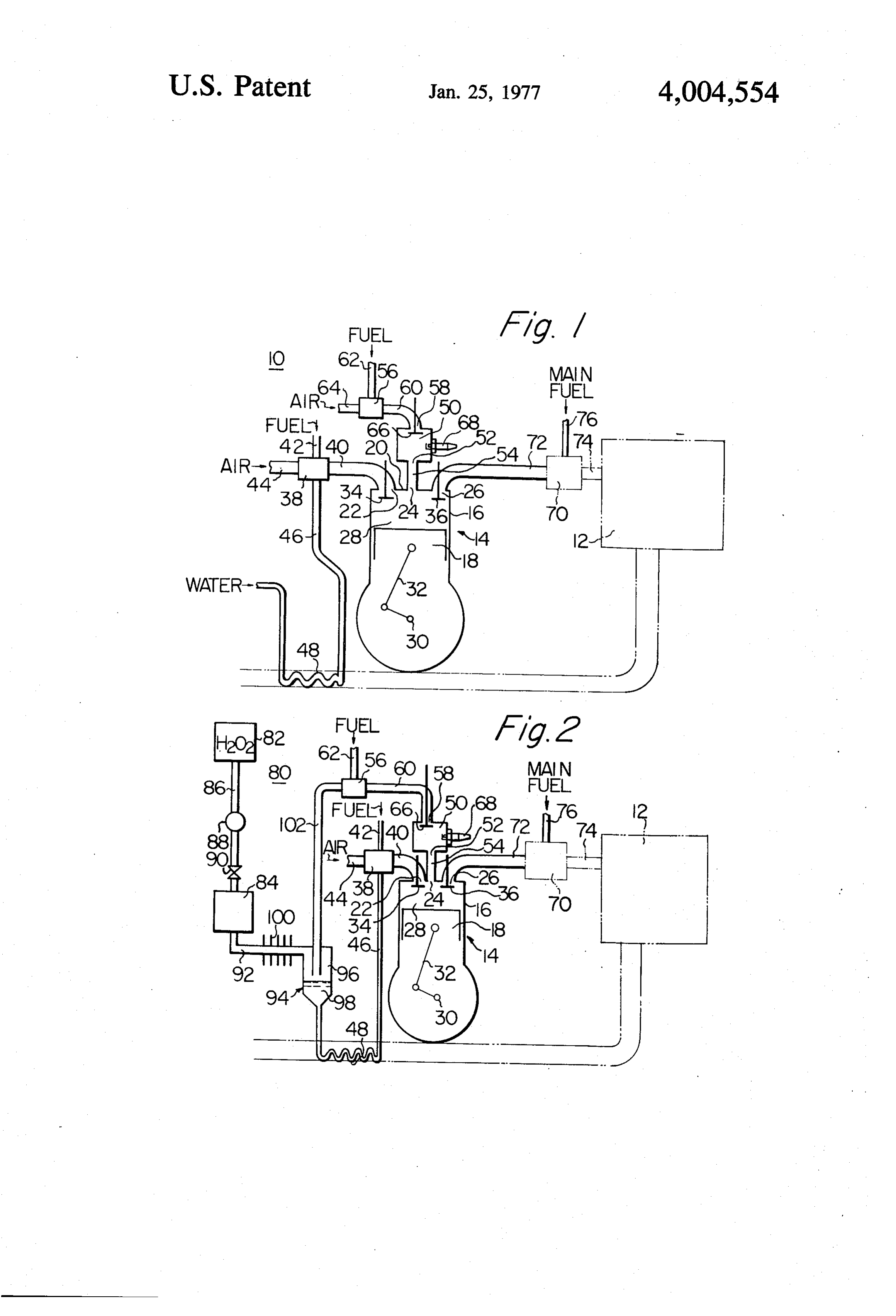
of and a apparatus for producing hydrogen and particu These and other objects and advantages of the inven larly to a method of converting or cracking a hydrocar tion will become more apparent from the following bon fuel into a free hydrogen containing gas and an detailed description taken with reference to the accom apparatus for accomplishing the same. panying drawings in which: It is recognized in the art that if hydrogen is added to FIG. 1 is a schematic view of a first preferred em a hydrocarbon fuel which is supplied into an internal 10 bodiment of a fuel converting or cracking apparatus combustion engine, the engine can use an air-fuel mix according to the invention; and ture containing more air than is stoichiometrically re FIG. 2 is a schematic view of a second preferred quired for complete combustion. This is because the embodiment of a fuel converting or cracking apparatus mixture is activated by hydrogen added thereto. As a according to the invention.
result, the engine discharges an exhaust gas which con 5 Referring to FIG. 1, there is shown a fuel converting tains considerably low concentrations of harmful com or cracking apparatus according to the invention gen ponents such as hydrocarbons, carbon monoxide and erally designated by the reference numeral 10, and an nitrogen oxides. internal combustion engine 12 of a motor vehicle (not In the application of such a technique to an engine of shown). The fuel converting apparatus 10 is shown to an ordinary motor vehicle such as a passenger car, it is 20 comprise a displacement expander 14 of a four-cycle dangerous to equip the vehicle with a hydrogen storing reciprocating piston type. The expander 14 comprises a container as there is a possibility of explosion. Thus, for cylinder 16 and a piston 18 which is axially reciprocally safety purposes it is desirable to provide the vehicle slidably fitted in the cylinder 16. The cylinder 16 has a with an apparatus which produces hydrogen to be cylinder head 20 which is formed with an intake port added to a fuel of the engine as required. Thus to pro 25 22, a flame spouting port 24 and an exhaust port 26 duce hydrogen, it is desirable to utilize the so-called therethrough. The piston 18 performs intake, compres "partial oxidation or combustion process' which pro sion, expansion and exhaust strokes in sequence to duces a free hydrogen containing gas from hydrocar define a variable volume main or expander chamber 28 bons. According to this process, hydrocarbons are in the cylinder 16. The expander chamber 28 serves as mixed with one third of the oxygen or air stoichiometri 30 a reaction or fuel converting chamber during the ex cally required for complete combustion. The resultant pansion stroke of the piston 18. The piston 18 is opera mixture of hydrocarbons and oxygen or air is then tively connected to a crankshaft 30 by means of a con partially oxidized under a high pressure, high tempera necting rod 32. A flywheel (not shown) is mounted on ture environment. The hydrocarbons are thus decom the crankshaft 30 at one end thereof. The intake and posed or converted or cracked into a free hydrogen and 35 exhaust ports 24 and 26 are provided therein with in carbon monoxide rich gas in the presence of water. The take and exhaust valves 34 and 36, respectively. The above reaction is exothermic and the free hydrogen intake and exhaust valves 34 and 36 are normally containing gas produced has a high temperature. closed and are operated by cams (not shown) on a shaft Accordingly, the following three problems are en (not shown) driven by the crankshaft 30, so that the countered in executing the partial oxidation process: 40 intake valve 24 is opened during the intake stroke of 1. Power is required for highly compressing the mix the piston 18 and the exhaust valve 26 is opened during ture of hydrocarbons and oxygen or air. Thus in a car the exhaust stroke of the piston 18. this results in an increase in the load demand on the The expander 14 is provided with a main mixing engine or power loss of the engine or requires provision chamber or device 38 which communicates with the for compression. 45 intake port 22 by way of a main intake conduit 40. A 2. It is necessary to maintain a constant supply of source (not shown) of hydrocarbon fuel is provided to hydrogen to the engine. Thus the fuel converting or communicate with the mixing chamber 38 by way of a cracking reaction must take place at a high rate. There conduit 42 for supply of fuel thereto. The fuel may be fore to achieve this rate in the presence of such a lean a liquid fuel. A source (not shown) of air is provided to oxygen supply it is necessary to compress and heat the 50 communicate with the mixing chamber 38 by way of a mixture to a considerably high level. However if adia conduit 44 for supply of air thereto. A source of water batic compression is used, the weight of the apparatus or water vapour such as a water tank (not shown) is is so great that it is of no practical use. provided to communicate with the mixing chamber 38 3. It is necessary to reduce the temperature of the by way of a conduit 46 for supply of water or water free hydrogen containing gas so that it may be safely 55 vapour thereto. The source of air may be the outside fed into an engine. Thus a cooler is necessary. atmosphere to which the conduit 44 is vented by way of It is, therefore, an object of the invention to provide an air cleaner (not shown). The mixing chamber 38 a method of and an apparatus for converting or crack may be formed therein with a venturi section (not ing hydrocarbon fuel into a free hydrogen containing shown) through which air passes to the expander cham gas in which the gas expands to perform work which is 60 ber 28 and into which the conduits 42 and 46 open. accumulated for use in the subsequent operations, and The flow of air passing through the venturi section in which the temperature is simultaneously reduced. during the intake stroke of the piston 18 produces a Thus power and heat losses are reduced, for example, vacuum in the venturi section to draw or induct fuel down to zero. and water vapour from the conduits 42 and 46, respec It is a further object of the invention to provide a 65 tively. Pumps (not shown) may be disposed in the con method and apparatus in which a combustible mixture duits 42, 44 and 46 to inject or spray fuel, air and water is ignited to produce a flame which is spouted into a under pressure, respectively, therefrom into the mixing base mixture of hydrocarbons, oxygen or air and water chamber 38. In this instance, the venturi section in the
Page 4
mixing chamber 38 may be dispensed with. The fuel, port 26 by way of an exhaust conduit 72 for supply of air and water or water vapour supplied into the mixing the free hydrogen containing gas thereto. The mixing chamber 38 are mixed with each other to produce a chamber 70 also communicates with an intake port base mixture which is supplied into the expander cham (not shown) of the engine 12 by way of a conduit 74. A ber 28 for compression and conversion thereof into a source (not shown) of hydrocarbon fuel for the engine free hydrogen containing gas. Suitable control means 12 is provided to communicate with the mixing cham such as a flow control valve (not shown) may be pro ber 70 by way of a conduit 76 for supply of the main vided in each of the conduits 42, 44 and 46 to meter the fuel thereto. The mixing chamber 70 may be formed flow of fluid passing therethrough in such a manner therein with a venturi section (not shown) through that the base mixture has a predetermined fuel-air 10 which the free hydrogen containing gas passes and into water ratio. A heat exchanger 48 may be disposed in which the conduit 76 opens. The flow of the free hydro the conduit 46 so that exhaust gas from the engine 12 gen containing gas passing through the venturi section heats water supplied to the mixing chamber 38 to pro during the exhaust stroke of the piston 18 and/or an duce water vapour. As a result, the thermal efficiency intake stroke of the engine 12 produces vacuum in the of the engine 12 is increased. 15 venturi section to draw or induct fuel from the conduit The expander 14 is also provided with an auxiliary or 76 thereinto. A pump may be provided in the conduit combustion chamber 50 which communicates at an 76 to inject fuel under pressure from the source of fuel outlet port 52 with the port 24 by way of a conduit 54 into the mixing chamber 70. In this instance, the ven and an auxiliary mixing chamber or device 56 which turi section in the mixing chamber 70 may be dispensed communicates with an inlet port 58 of the combustion 20 with. The fuel and the free hydrogen containing gas chamber 50 by way of an auxiliary intake conduit 60. A supplied into the mixing chamber 70 are mixed with source (not shown) of hydrocarbon fuel is provided to each other to produce a mixture which is supplied to a communicate with the auxiliary mixing chamber 56 by combustion chamber or chambers (not shown) of the way of a conduit 62 for supply of fuel thereto. The fuel engine 12. Suitable control means such as a flow con may be a liquid fuel. A source (not shown) of air is 25 trol valve (not shown) may be provided in the conduit provided to communicate with the auxiliary mixing 76 to meter the flow of fuel passing therethrough in chamber 56 by way of a conduit 64 for supply of air such a manner that the fuel has a predetermined pro thereto. The source of air may also be the outside at portion with respect to the free hydrogen containing mosphere to which the conduit 64 is vented by way of gas. The amount of the base mixture produced in the an air cleaner (not shown). The auxiliary mixing cham 30 main mixing chamber 38 is controlled by the control ber 56 may be formed therein with a venturi section means mentioned hereinbefore in such a manner that (not shown) through which air passes to the combus the free hydrogen containing gas has a predetermined tion chamber 50 and into which the conduit 62 opens. proportion to the main fuel which is supplied to the The flow of air passing through the venturi section engine.
during the intake stroke of the piston 18 produces a 35 The operation of the fuel converting system 10 ac vacuum in the venturi section to draw or induct fuel cording to the invention thus constructed and arranged from the conduit 62 thereinto. Alternatively pumps is as follows.
(not shown) may be disposed in the conduits 62 and 64 The expander 14 is started by suitable means such as to inject fuel and air under pressure, respectively, a starter motor (not shown). During the intake stroke therefrom into the auxiliary mixing chamber 56. In this 40 of the piston 18, the intake valve 34 is opened with the instance, the venturi section in the auxiliary mixing exhaust valve 36 closed so that the base mixture is chamber 56 may be dispensed with. The fuel and air drawn from the main mixing chamber 38 into the ex supplied into the mixing chamber 56 are mixed with pander chamber 28 through the conduit 40 by the each other to produce a combustible mixture which is suction movement of the piston 18. Concurrently, the supplied into the combustion chamber 50 for combus 45 inlet valve 66 is opened so that the combustible mixture tion thereof. Suitable control means such as a flow is drawn from the auxiliary mixing chamber 56 into the control valve (not shown) may be provided in each of combustion chamber 50 through the conduit 60 by the the conduits 62 and 64 to meter the flow of fluid pass suction movement of the piston 18. Next, during the ing therethrough in such a manner that the combustible compression stroke of the piston 18, the valves 34 and mixture has a predetermined air-fuel ratio. The com 50 66 are closed and the base mixture drawn into the bustible mixture may have, for example, an air-fuel expander chamber 28 is compressed by the compres ratio near the stoichiometric air-fuel ratio, but it is sion movement of the piston 18 so that the temperature preferable to avoid same in order to avoid production of the base mixture is elevated to a high level. The of large quantities of nitrogen oxides in combustion of spark plug 68 is energized to produce a spark in the the combustible mixture in the combustion chamber 55 combustion chamber 50 to ignite the combustible mix 50. The inlet port 58 of the combustion chamber 50 is ture immediately before the top dead center of the provided with an inlet valve 66 therein. The inlet valve compression stroke of the piston 18. As a result, the 66 is normally closed and is operated by a cam (not combustible mixture is quickly burned in the combus shown) on a shaft (not shown) driven from the crank tion chamber 50 to produce a flame of a high tempera shaft 30 so that it is synchronously opened with the 60 ture and at a high pressure. The flame is spurted from intake valve 34. A spark plug 68 is provided in the the combustion chamber 50 into the expander chamber combustion chamber 50 and, when energized, pro 28 through the conduit 54. The base mixture is agitated duces a spark therein to ignite the combustible mixture and heated to a higher temperature by the flame. As a to produce a flame. result, a rapid fuel converting reaction takes place in The expander 14 is also provided with a mixing 65 the base mixture to decompose and convert hydrocar chamber or device 70 for mixing of the free hydrogen bons of the base mixture into a gas which contains high containing gas with the main fuel for the engine 12. The concentrations of free hydrogen and carbon monoxide. mixing chamber 70 communicates with the exhaust The resultant gas expands to force the piston 18 to
Page 5
cause the expansion stroke of the piston 18. Thus a disposed in the conduit 92 at a location between the large portion of heat energy of the free hydrogen con decomposition chamber 84 and the separator 94 to taining gas is converted into work energy during expan cool oxygen and steam supplied from the decomposi sion of the gas so that the temperature of the gas is tion chamber 84. The oxygen containing section 96 reduced, for example, to a level at which the gas has no communicates with the auxiliary mixing chamber 56 by detrimental effect on the operation of the engine 12 way of a conduit 102. The water containing section 98 when the gas is supplied thereto. Thus, heat loss is is employed as a source of water for the main mixing reduced, for example, down to zero. Accordingly, it is chamber 38 and communicates with a conduit 46 unnecessary to provide a radiator or cooler to cool the which communicates with the mixing chamber 38. free hydrogen containing gas. A radiator or cooler may 10 Oxygen supplied into the auxiliary mixing chamber be provided, of course. The work of expansion of the 56 is mixed with fuel supplied from the source of fuel to free hydrogen containing gas is accumulated in the produce a combustible mixture which is supplied to the flywheel and other working or moving components as combustion chamber 50 for combustion therein and for power which is employed to cause the subsequent ex formation of a flame. Since the auxiliary mixing cham haust, intake and compression strokes of the piston 18. 15 ber 56 is supplied with oxygen resulting from decompo As a result, the piston 18 is driven by the inertia of the sition of hydrogen peroxide in lieu of air in this manner, flywheel and other working members, during the ex the combustible mixture is not diluted by nitrogen haust, intake and compression strokes of the piston 18. forming a part of air. As a result, fuel molecules will Thus, the expander 14 does not increase the load de rapidly find and react with oxygen molecules to pro mand on the engine 12 or cause power loss of the en 20 duce rapid and complete combustion in the combus gine nor does it require provision for driving the piston tion chamber 50. Accordingly, a flame will be pro 18, and is thus self operating or perpetuating except duced which has a higher temperature and is under during starting. - higher pressure than the flame produced from the com During the exhaust stroke of the piston 18, the ex bustible mixture formed from fuel and air which is haust valve 36 is opened with the valves 34 and 66 25 described above with reference to FIG. I. Conse closed so that the free hydrogen containing gas is dis quently, a more complete fuel converting or cracking charged from the expander chamber 28 into the mixing reaction in the expander chamber 28 is promoted dur chamber 70 through the conduit 72 by the exhaust ing the expansion stroke of the piston 18 to convert the movement of the piston 18 where it is mixed with fuel. base mixture into a free hydrogen containing gas. Fur Referring to FIG. 2, there is shown a second pre 30 thermore, production of nitrogen oxides is reduced to ferred embodiment of a fuel converting or cracking AcO.
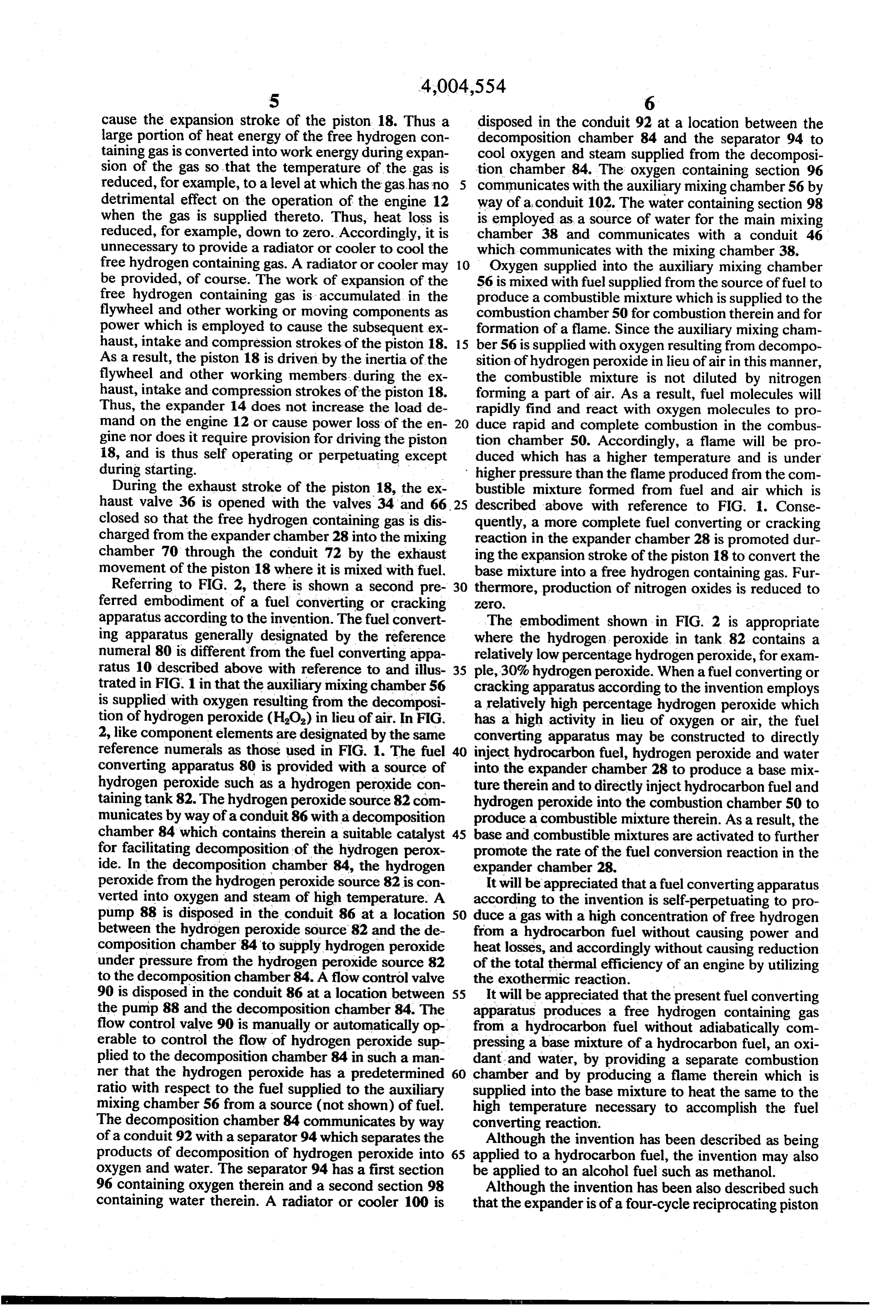
apparatus according to the invention. The fuel convert The embodiment shown in FIG. 2 is appropriate ing apparatus generally designated by the reference where the hydrogen peroxide in tank. 82 contains a numeral 80 is different from the fuel converting appa relatively low percentage hydrogen peroxide, for exam ratus 10 described above with reference to and illus 35 ple, 30% hydrogen peroxide. When a fuel converting or trated in FIG. 1 in that the auxiliary mixing chamber 56 cracking apparatus according to the invention employs is supplied with oxygen resulting from the decomposi a relatively high percentage hydrogen peroxide which tion of hydrogen peroxide (HO) in lieu of air. In FIG. has a high activity in lieu of oxygen or air, the fuel 2, like component elements are designated by the same converting apparatus may be constructed to directly reference numerals as those used in FIG. 1. The fuel 40 inject hydrocarbon fuel, hydrogen peroxide and water converting apparatus 80 is provided with a source of into the expander chamber 28 to produce a base mix hydrogen peroxide such as a hydrogen peroxide con ture therein and to directly inject hydrocarbon fuel and taining tank 82. The hydrogen peroxide source 82 com hydrogen peroxide into the combustion chamber 50 to municates by way of a conduit 86 with a decomposition produce a combustible mixture therein. As a result, the chamber 84 which contains therein a suitable catalyst 45 base and combustible mixtures are activated to further for facilitating decomposition of the hydrogen perox promote the rate of the fuel conversion reaction in the ide. In the decomposition chamber 84, the hydrogen expander chamber 28.
peroxide from the hydrogen peroxide source 82 is con It will be appreciated that a fuel converting apparatus verted into oxygen and steam of high temperature. A according to the invention is self-perpetuating to pro pump 88 is disposed in the conduit 86 at a location 50 duce a gas with a high concentration of free hydrogen between the hydrogen peroxide source 82 and the de from a hydrocarbon fuel without causing power and composition chamber 84 to supply hydrogen peroxide heat losses, and accordingly without causing reduction under pressure from the hydrogen peroxide source 82 of the total thermal efficiency of an engine by utilizing to the decomposition chamber 84. A flow control valve the exothermic reaction.
90 is disposed in the conduit 86 at a location between 55 It will be appreciated that the present fuel converting the pump 88 and the decomposition chamber 84. The apparatus produces a free hydrogen containing gas flow control valve 90 is manually or automatically op from a hydrocarbon fuel without adiabatically com erable to control the flow of hydrogen peroxide sup pressing a base mixture of a hydrocarbon fuel, an oxi plied to the decomposition chamber 84 in such a man dant and water, by providing a separate combustion ner that the hydrogen peroxide has a predetermined 60 chamber and by producing a flame therein which is ratio with respect to the fuel supplied to the auxiliary supplied into the base mixture to heat the same to the mixing chamber 56 from a source (not shown) of fuel. high temperature necessary to accomplish the fuel The decomposition chamber 84 communicates by way converting reaction.
of a conduit 92 with a separator 94 which separates the Although the invention has been described as being products of decomposition of hydrogen peroxide into 65 applied to a hydrocarbon fuel, the invention may also oxygen and water. The separator 94 has a first section be applied to an alcohol fuel such as methanol. 96 containing oxygen therein and a second section 98 Although the invention has been also described such containing water therein. A radiator or cooler 100 is that the expander is of a four-cycle reciprocating piston
Page 6
type, it can be also of a two-cycle reciprocating piston member to accumulate power for causing said working type or a rotary piston type. member to perform said compression stroke thereof. What is claimed is: 6. A fuel converting apparatus as claimed in claim 5, 1. A method of converting a fuel into a free hydrogen in which said means for filling said expander chamber containing gas, comprising the steps of filling a first with said base mixture comprises a main mixing cham space with a base mixture of fuel, oxidant and water ber which communicates with fuel supply means, oxi having a predetermined ratio to each other, compress dant supply means and water supply means for supply ing said base mixture, filling separately a second space of fuel, oxidant and water, respectively, thereto and for with a combustible mixture of fuel and oxidant having formation of said base mixture therein and which com a predetermined ratio to each other, igniting said com O municates with said expander chamber for supply of bustible mixture to produce a flame, spurting said said base mixture thereto, and said means for filling flame into said compressed base mixture, causing con said combustion chamber with said combustible mix version of said base mixture into a free hydrogen con ture comprises an auxiliary mixing chamber which taining gas and expansion of said free hydrogen con communicates with fuel supply means and oxidant taining gas by heat of said flame, making said free hy 15 supply means for supply of fuel and oxidant, respec drogen containing gas perform work during expansion tively, thereto and for formation of said combustible of said gas, accumulating said work performed by said mixture therein and which communicates with said free hydrogen containing gas as power for compressing combustion chamber for supply of said combustible mixture thereto.
said base mixture.
2. A method as claimed in claim 1, in which the step 20 in 7.which A fuel converting apparatus as claimed in claim 6, said water supply means comprises a heat of filling said first space with said base mixture is ef exchanger receiving engine exhaust gas thus heating fected by forming said base mixture, and supplying said water supplied base mixture into said first space, and the step of filling water vapour. to said main mixing chamber to produce said second space with said combustible mixture is effected by forming said combustible mixture, and 25 in 8.which A fuel converting apparatus as claimed in claim 7, said water supply means and said oxidant supplying said combustible mixture into said second supply means for said auxiliary mixing chamber com space.
prises a source 3. A method as claimed in claim 1, in which the step chamber communicating of hydrogen peroxide, a decomposition of igniting said combustible mixture is performed im 30 peroxide to decompose hydrogen with said source of hydrogen mediately before termination of the step of compress source, and a separator communicating peroxide from said ing said base mixture. with said de composition chamber to separate the products of de 4. A method as claimed in claim 1, further compris composition of hydrogen peroxide therefrom into oxy ing the steps of discharging said free hydrogen contain gen ing gas to a third space, filling said third space with fuel 35 and and
water and having an oxygen containing section water containing section, in which said water for an engine and mixing said free hydrogen containing containing section communicates with said main mix gas with said fuel for said engine. ing chamber for supply of water thereto, and said oxy 5. A fuel converting apparatus for converting fuel gen containing section communicates with said auxil into a free hydrogen containing gas, comprising a dis iary mixing chamber for supply of oxygen placement expander having a housing and a working 40 9. A fuel converting apparatus as claimedthereto. in claim 8, member performing compression and expansion in which said water supply means further comprises a strokes in said housing to define a variable volume heat exchanger disposed between said main mixing expander chamber therein, means for filling said ex chamber and said water containing section to receive pander chamber with a base mixture of fuel, oxidant engine exhaust gas and to heat water supplied to said and water having a predetermined ratio to each other, 45 main mixing chamber to produce water vapour. said working member compressing said base mixture 10. A fuel converting apparatus as claimed in claim during said compression stroke thereof, a combustion 5,in which said combustible mixture is ignited immedi chamber communicating with said expander chamber, ately before termination of said compression stroke of means for filling said combustion chamber with a com said working member.
bustible mixture of fuel and oxidant having a predeter SO 11. A fuel converting apparatus as claimed in claim mined ratio to each other, means for igniting said com 5, further comprising a mixing chamber communicat bustible mixture in said combustion chamber to pro ing with said expander chamber, and means for causing duce a flame, means for causing ejection of said flame discharge of said free hydrogen containing gas to the from said combustion chamber into said expander last-mentioned mixing chamber, the last-mentioned chamber so that heat of said flame causes conversion of 55 mixing chamber communicating with fuel supply said base mixture into a free hydrogen containing gas means for supply of fuel thereto and for mixing of fuel and causes expansion of said free hydrogen containing with said free hydrogen containing gas and communi gas to make said working member perform said expan cating with an engine for supply of a mixture of said sion stroke thereof, means driven by said working free hydrogen containing gas and said fuel thereto. member during said expansion stroke of said working 60 sk sk sk sk xk
Provenance
- Collection
- Cited prior art
- Original PDF
- patentimages.storage.googleapis.com →
- Filed
- 1975-02-20
- Pages
- 6
- Method
- pdftotext (the PDF's own text layer) + pdftoppm 300dpi page scans
- Source
- Google Patents bibliographic record
- Granted
- 1977-01-25
- Inventors
- Katuaki Kosaka; Zene Ueno; Tadahiko Nagaoka; Nissan Motor Co Ltd
- Transcribed from
- patentimages.storage.googleapis.com →