patent · US4033133
Start up system for hydrogen generator used with an internal combustion engine
5 July 1977
Page 1 — bibliographic record
United States Patent (19) 11) 4,033,133 Houseman et al. 45) July 5, 1977 54) START UP SYSTEM FOR HYDROGEN 3,635,200 1/1972 Rundell et al. ........................ 123/3 GENERATOR USED WITH AN INTERNAL 3,717,129 2/1973 Fox .................................... 12311 A COMBUSTION ENGINE 3,732,690 5/1973 Meijer ............................... 123/1 A 3,908,606 9/1975 Toyoda et al. ....................... 23/3 75 Inventors: John Houseman, Pasadena; Donald 3,911,675 10/1975 Mondt ................................. 60/300 J. Cerini, Flintridge, both of Calif. 3,954,423 5/1976 Hamper et al. ... ... 48/107
(73) Assignee: California Institute of Technology, Primary Examiner-Robert L. Lindsay, Jr. Pasadena, Calif. Assistant Examiner-George C. Yeung 22 Filed: Mar. 22, 1976 Attorney, Agent, or Firm-Frielich, Lindenberg (21) Appl. No.: 668,783 57 ABSTRACT (52) U.S. Cl. ............................... 60/606; 23/288 R; A hydrogen generator provides hydrogen rich product 48/61; 48/102 A; 48/103; 48/107; 48/117; gases which are mixed with the fuel being supplied to 48/DIG. 8; 60/300; 12313; 123/179 R; an internal combustion engine for the purpose of en 123/DIG. 12; 423/650 abling a very lean mixture of that fuel to be used, 51 int. Cl'......................................... FO2B 33/44 whereby nitrous oxides emitted by the engine are mini 58) Field of Search ...... 48/61, 1 16, 117, 102-103, mized. The hydrogen generator contains a catalyst 48/107, DIG. 8, 197 R, 199 R, 212, 213; which must be heated to a pre-determined temperature 12313, 1 A, 179R, DIG. 12; 60/300, 606; before it can react properly. To simplify the process of 23/281, 288 R; 252/373; 431/DIG. 68; heating up the catalyst at start-up time, either some of 423/650 the energy produced by the engine such as engine ex (56) References Cited haust gas, or electrical energy produced by the engine, or the engine exhaust gas may be used to heat up air
UNITED STATES PATENTS which is then used to heat the catalyst.
2,803,295 8/1957 Ambrose et al. .................... 48/103 2,897,073 7/1959 Shipp ................................... 48/103 9 Claims, 6 Drawing Figures
ENGINE
THROTTLE
ENGINE
ARATOMZER
BOOSTER PUMP
SENSING
CONTROL
ATM
EXHAUST
Page 2
Drawing sheet — no readable text.
Page 3
SUPER
ATM
EXHAUST
CHARGER
ATM
EXHAUST
------- res w- - - - - - - -w m arow - we anal wu- - amwo mo -- - HYDROGEN RICH GAS N/
F G. 2 76 VENT
SOURCE
OF FUEL
Page 4
Drawing sheet — no readable text.
Page 5
Drawing sheet — no readable text.
Page 6
Drawing sheet — no readable text.
Page 7
Drawing sheet — no readable text.
Page 8
less operation within the catalyst bed. Switching the
START UP SYSTEM FOR HYDROGEN air/fuel ratio from 10 to 5.2 during start-up requires an GENERATOR USED WITH AN INTERNAL appropriate control system which adds to the overall COMBUSTON ENGINE complexity and which reduces the overall reliability. ORIGIN OF THE INVENTION Accordingly, a start-up system which would avoid overheating the catalyst and the need for apparatus for
The invention described herein was made in the per changing the air/fuel ratio from a start-up value to an formance of work under a NASA contract and is sub operating value would result in a less expensive cata ject to the provisions of Section 305 of the NASA Act lytic converter, as well as one which avoids the possibil of 1958, Public Law 85-568 (72 Stat. 435; 42 USC 2457). 10 ity of damage or plugging of the catalytic converter 2457). bed.
BACKGROUND OF THE INVENTION
OBJECTS AND SUMMARY OF THE INVENTION
This invention relates to internal combustion en gines, and more particularly to a system for supplying 15 It is an object of this invention to provide a catalytic fuel to the engine. converter start-up system which eliminates the need for In an application Ser. No. 487,156 filed July 10, a start-up burner as well as the need for changing the 1974, now U.S. Pat. No. 3,982,910, by these inventors, air/fuel ratio from one value used at start-up to another which is entitled Hydrogen Rich Gas Generator, there value used during regular operation.
is described and claimed a generator for producing 20 It is another object of the present invention to pro hydrogen rich gas from hydrocarbon fuels. The genera vide a new and improved start-up system for a hydro tor has a catalytic bed containing particles of a partial gen fuel generator using a catalytic converter. oxidation catalyst, such as nickel, or platinum or silver Yet another object of this invention is the provision oxide. A hydrocarbon fuel is mixed with air and then of a start-up system for a hydrogen generator using a injected into a chamber where the mixture is ignited 25 catalytic converter, which avoids the possibility of using a means, such as a spark.plug. The ignited mix ture produces a flame and gases which flow through the damaging the catalytic converter. The foregoing and other objects of the invention are catalytic bed to heat it up to a required operating tem achieved perature. As the catalytic bed heats up beyond 900°F, which theinhydrogen an arrangement wherein the engine with generator is associated is initially the flame gradually moves into the catalytic bed and 30 when a steady state temperature of 1800° F is reached started in its usual manner. Energy generated by the there is no visible flame present and the requirement engine is used to heat up the catalytic bed. The engine for igniting the air and hydrocarbon fuel mixture is no produces exhaust gas which is sufficiently hot so that it longer necessary, since ignition is caused to occur by can be either applied directly to the catalytic bed of the the hot catalytic bed. 35 hydrogen generator to rapidly heat it to the required The catalytic bed converts the air and fuel mixture start-off temperature, at which point the exhaust gas is passing therethrough into hydrogen rich product gases no longer used, or the exhaust gas may be used to pre which are then collected and mixed with fuel and air heat air which is then applied to the catalytic bed to which is then fed into the cylinders of the internal com cause its temperature to rise to the start-off tempera bustion engine. 40 ture. At that time the air can be turned off. Another A preferred catalyst is a nickel catalyst. However, the catalytic converter preheat system in accordance with manufacturer of this catalyst recommends that the nickel not be exposed to temperatures above 2200 F. this invention is to imbed electrical heater wires in the It was previously indicated that start up requires first until the bed catalytic bed and apply electrical current to the wires reaches the required temperature.
igniting gases with a burner, which gases are passed 45 through the catalytic bed until it is heated to its light-off The novel features of the invention are set forth with temperature, (the temperature at which the reaction particularity in the appended claims. The invention will starts). To keep the combustion gas temperature down, best be understood from the following description a rich combustion mixture is used with the flame tem when read in conjunction with the accompanying draw peratures on the order of 3000°F (hence the possibility 50 Ings.
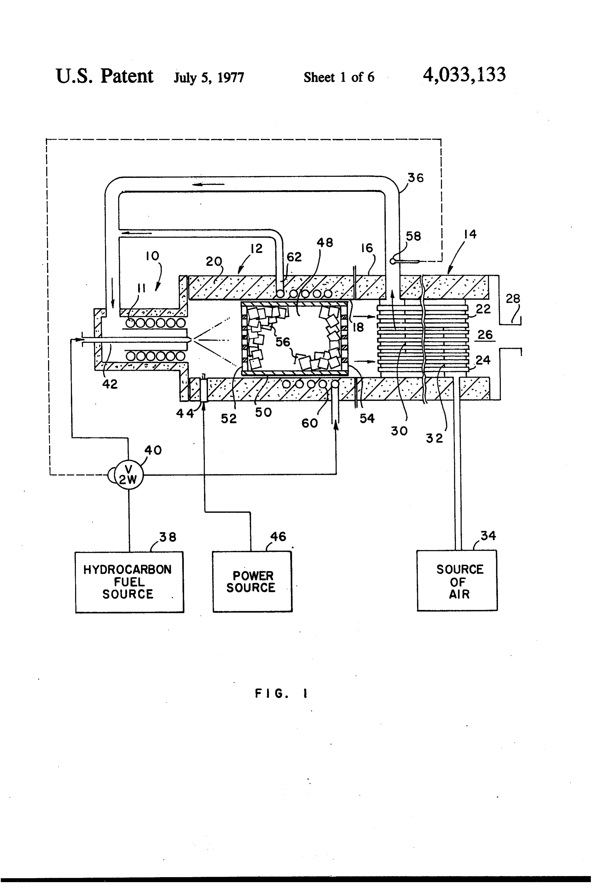
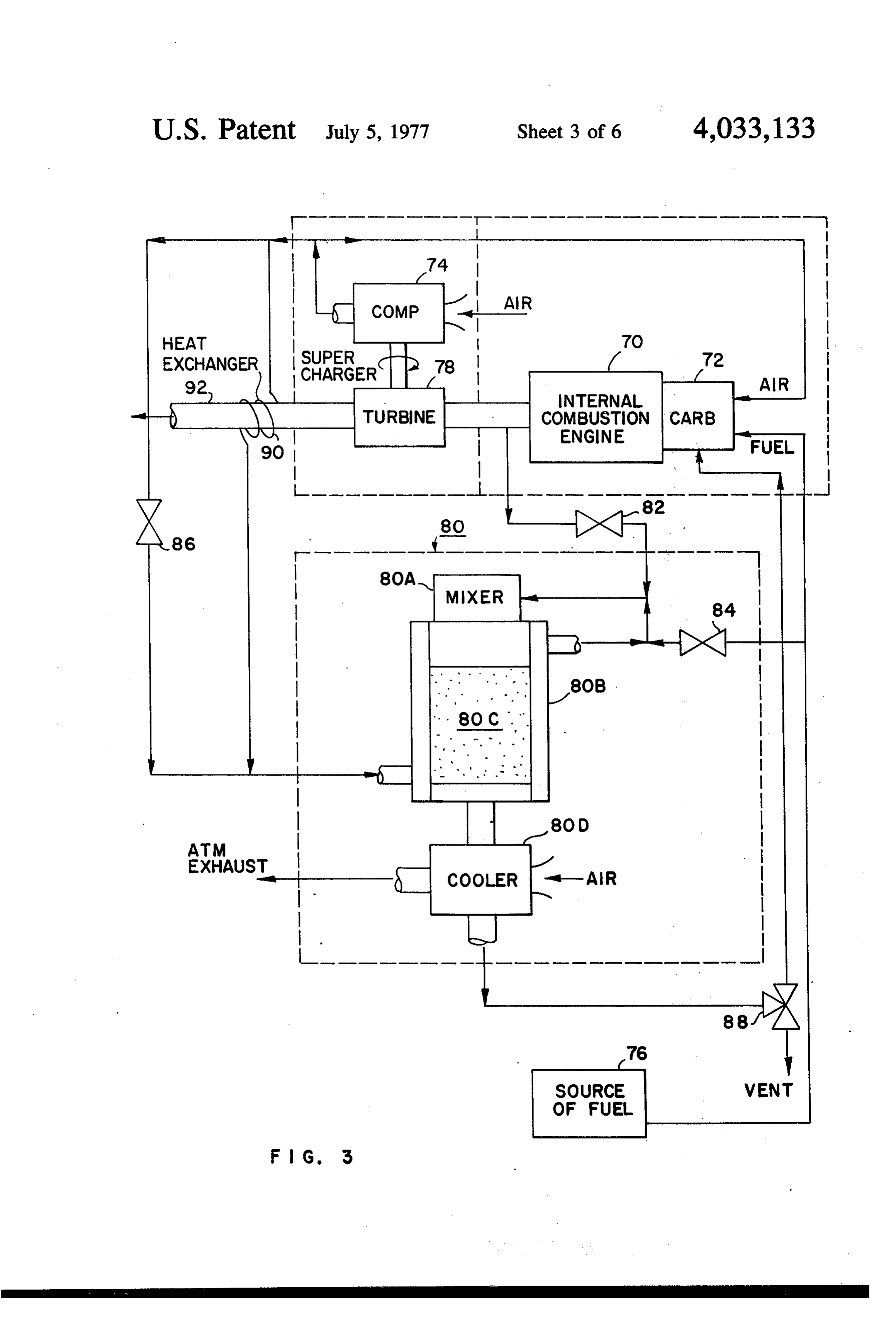
that some of the catalyst is heated to higher than the BRIEF DESCRIPTION OF THE DRAWINGS 2200 F maximum). The 3000 F corresponds to an air/fuel mass ratio of approximately 10. To produce a FIG. 1 is a schematic cross-sectional view of a hydro lower temperature combustion requires using a lower gen generator as described and shown in application air/fuel ratio. However, it is not feasible to use air/fuel 55 Ser. No. 487,156 filed July 10, 1974, now U.S. Pat. No. ratios below 10 as this results in soot formation. Soot 3,982,910, by these inventors. deposition on a catalyst, in turn, results in catalyst FIG. 2 is a schematic drawing illustrating one em deactivation and can also cause plugging of gas pas bodiment of this invention.
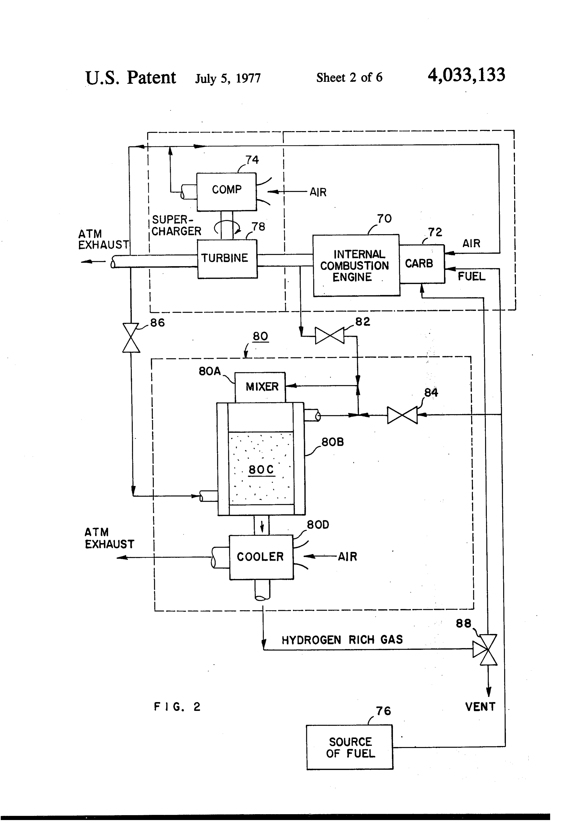
sages in the catalyst. Further, the temperature above FIG. 3 is a schematic drawing illustrating another 2300 F, causes a degradation of the catalyst active 60 embodiment of this invention. surface so that some capability is lost with each cold FIG. 4 is a schematic drawing illustrating still another start of the generator.
When a sufficient amount of catalyst surface has embodiment of this invention. FIG. 5 is a pictorial drawing of a hydrogen generator been heated above the light off temperature (800 -1000 F range for a nickel catalyst), the air/fuel ratio 65 suitable for use with the catalytic bed heating systems must be changed from the cold start value of 10 to the described, and operating value of 5.2. This procedure will then cause FIG. 6 is a schematic drawing of an improvement the transition from a luminous start-up flame to flame over FIG. 4.
Page 9
inner metal combustion shell or the inner wall 18 and is
DESCRIPTION OF THE PREFERRED embedded in the insulation 20.
EMBODIMENTS The vaporized fuel leaves the coil exit 62, and there FIG. 1 is a schematic drawing of a hydrogen genera after is mixed with the heated air stream coming out of tor using a catalytic converter and is identical with FIG. 5 the air exit flange 36. The pre-mixed vaporized fuel/air 10 in the previously mentioned application Ser. No. stream now passes through the mixer section 10 487,156. It is shown for the purpose of assisting in through the spiral tube 11, into the combustion cham providing a better understanding and appreciation of produce ber, where partial oxidation of the fuel takes place to this invention. The hydrogen generator basically com O when theatwo-way hydrogen rich gas. It should be noted that valve 40 is switched to the vaporized prises three sections, a mixer section 10, a combustion fuel position, the air/fuel section 12, and a preheater or heat exchange section ing value on the order ofratio is reduced to an operat 5.2. While air temperature 14. The combustion section and heat exchange section may be used to determine the propertime for operating together effectively constitutes a hollow cylinder hav ing an outer wall 16 and an inner wall 18 spaced there 15 the two-way valve so that the air/fuel mixture value is changed to the operating value, it is also possible to from. Suitable insulation 20, such as cast ceramic, is sense the catalytic temperature and when this reaches a positioned therebetween. The heat exchanging section predetermined value, the valve 40 may be operated to includes a plurality of hollow tubes, 22, 24, for exam the run mode, from the start-up mode. ple, which are spaced from one another and which In accordance with this invention, the construction of extend from the combustion section to a collection space 26, leading to the exhaust flange 28. 20 the catalytic converter is considerably simplified. Other A plurality of baffles, 30, 32, which are spaced from and lytic better means are provided for bringing the cata bed to its start-up temperature. The embodiments one another, extend from the opposite sides of the of the invention which are described subsequently inner walls in a manner so that the air, which is intro duced from a source of air 34, will follow a zigzag path herein include an aircraft piston type internal combus through the space between the tubes until the air 25 tion engine. However this should not be construed as a limitation on the invention, since those skilled in the art reaches an air exit passage 36, which is positioned at will the opposite end from the air entrance was to the heat any readily other understand how the invention may include type of internal combustion engine.
exchange region. In this manner the air comes in Referring now to FIG. 2, there may be seen a sche contact with the tubes through which hot hydrogen rich matic diagram of an arrangement in accordance with gases pass. The baffles 30, 32, provide for cross-flow of 30 this invention. An internal combustion engine, 70, has the air across these tubes and thus effectuate an effec tive heat transfer. a carburetor 72, to which air is supplied from an air The air leaves the exit flange 36 and is directed into compressor 74, and fuel is supplied from a source of fuel 76. The compressor 74 may be driven by a sepa the mixer section 10. The air circulates around a nozzle 42 and passes through spiral tubes 11 into the combus 35 rate electric motor, or may be driven by a turbine 78 tion section 12. At start-up, a liquid hydrocarbon fuel which in turn is driven by exhaust gases from the inter from a source 38, is pumped through a two-way valve nal combustion engine.
40, into the mixer section. The mixer section has the The hydrogen generator is included in the dotted start-up nozzle 42, which emits a spray of liquid drop 40 rectangle cludes a indicated by reference numeral, 80. It in mixer section 80A, a combustion section 80B, lets into the combustion chamber in combustion sec tion 12. The air/fuel mixture in the combustion cham having a catalytic bed 80C and a cooling section 80D. ber is ignited by a spark plug 44, which is powered from The combustion chamber as shown in FIG. 1 may be a source 46. A partial oxidation reaction then occurs. A omitted since it is not needed. The engine is started in its usual manner, without catalytic bed 48 is placed adjacent to the region where mixing combustion takes place during start-up. This bed com 45 valve 82anyis hydrogen rich gas with the incoming fuel. A opened to permit some of the exhaust gas prises a cylinder 50 which has a perforated top wall 52 from the internal combustion engine to enter into the and a perforated bottom wall 54, to permit hot gases to flow from the combustion region through the catalytic hydrogen generator by way of the mixer region 80A. A bed into the heat exchange section 14. The catalytic fuel valve 84, at this time, is closed, and an air valve 86, at this time, is also closed. A two-way valve 88, in one bed contains particles 56, of a partial oxidation catalyst 50 position vents the hydrogen gas generator, and in an such as nickel, deposited in a substrate such as alumi other position permits the hydrogen rich gas to be sup num pellets which serve to speed up the partial oxida plied to the carburetor of the internal combustion en tion reaction of the hydrogen carbon with air, to yield a hydrogen rich gas. Other partial oxidation catalysts, 55 gine. The fraction of the hot engine exhaust gas which enters the mixer 80A, by way of valve 82, has a temper such as palladium, platinum or silver oxide may also be ature on the order of between 1000 to 1200F and used for the reaction of hydrocarbon and air.
During start-up, the air/fuel ratio sprayed into the gas, whichthepasses heats up catalytic bed quickly. The engine exhaust through the hydrogen generator at combustion chamber is maintained above the vapor this time, is vented to the atmosphere through valve 88. ized fuel normal design value, such as 10. There is a temperature sensor 58, in the air exit flange, and when 60 When the catalytic bed has reached the temperature at this sensor detects the fact that a preset temperature which light-off occurs (approximately 900 F) the valve value has been exceeded by the preheated air, it con 82 of is closed, and valve 86 is opened to permit a fraction the air from the engine super charger to enter a trols the two-way valve 40 to prevent further applica heating tion of fuel to the start-up nozzle in the burner and 65 hydrogenjacket surrounding the catalytic bed of the generator. The jacket heats the air received instead supplies the fuel to a fuel vaporization coil 60. to a temperature, slightly higher than the ambient, Changes in the amount of fuel delivered to the burner which for steady state conditions is approximately 400' and to the vaporizer are determined by the sizes of the F. Fuel valve 84 is opened and valve 88 is operated at two way valve exit parts. The coil 64 is wound on the
Page 10
this time to the position which permits gas exiting from the light off temperature, valve 82 is turned from its the generator to enter the carburetor of the engine. The open to its closed position and valves 84 and 86 are fuel valve 84 is also opened at this time and the rate of opened from their closed positions. Valve 88 is oper fuel entering the mixer 80A is slowly increased. The ated from the vent position to the position at which it fuel is completely vaporized in the mixer by the heated feeds back hydrogen rich product gas to the carbure air. The vaporizer fuel/air mixture entering the cata tor. Alternatively, a sensing device in the catalytic bed lytic bed 80C will start to react with the catalyst and the can be used to control the valves, which may be sole subsequent temperature in the bed will reach a steady noid actuated, so that they can be electrically operated state at approximately 1800 F. between their closed and opened positions. The tech The exiting hydrogen-rich product gas passes O nique for controlling solenoid operated valves from a through the supplementary air cooled product-gas temperature sensing device is well-known and need not cooler 80D and exits the hydrogen generator at approx be shown here.
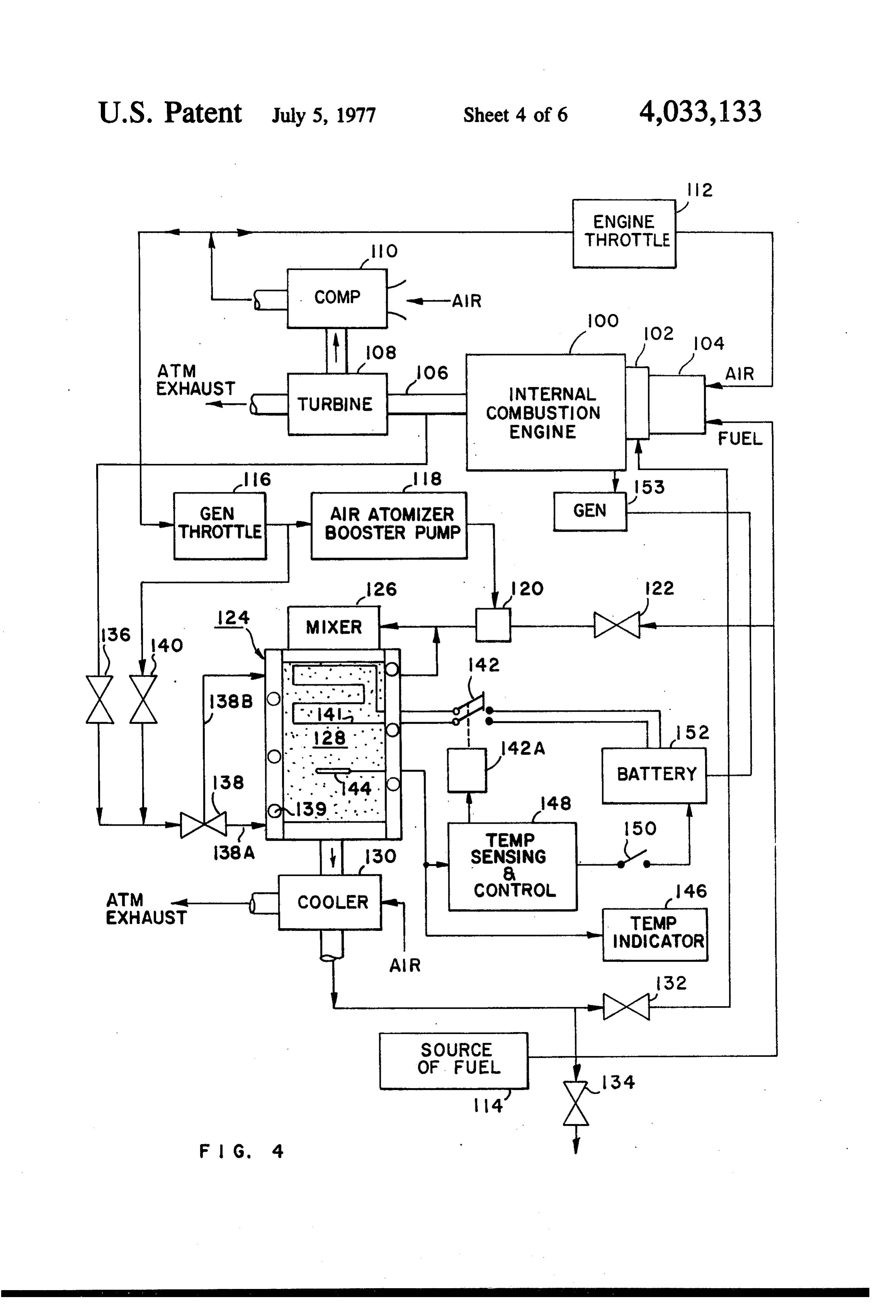
imately 500°F or below. It is fed to the engine carbure Referring now to FIG. 4, there may be seen a sche tor through the valve 88. matic diagram of another embodiment of the invention. By way of example, a carburetor suitable for use for 15 The systems shown can either use exhaust gases alone enabling engine start-up and for thereafter mixing the for preheating the catalytic bed, or a system using elec hydrogen rich product gas with the fuel and air in the trical heating wires in the bed for preheating, or a com proper proportions is shown and described in a patent bination of both if desired.
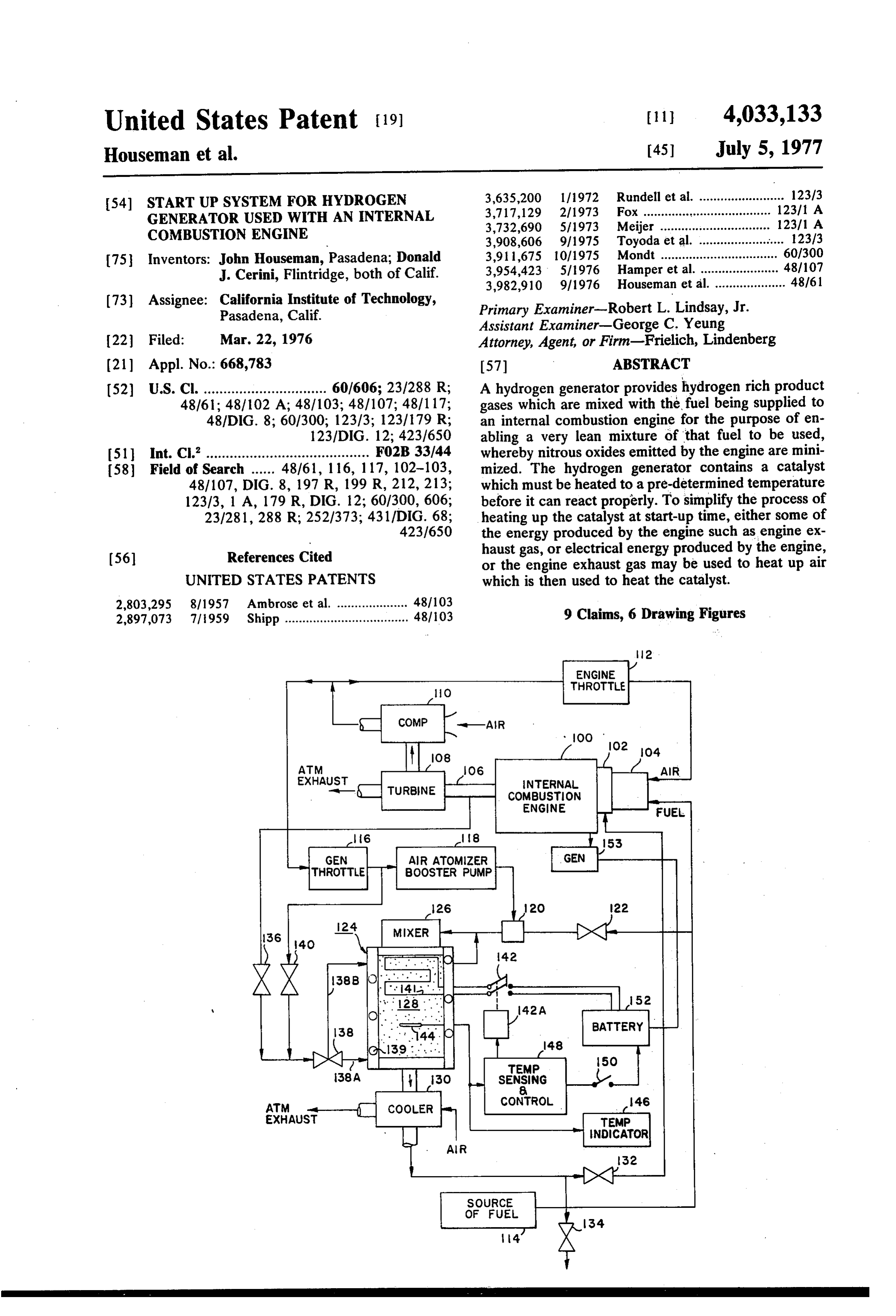
by J. Rupe U.S. Pat. No. 3,906, 913. Schematically represented in FIG. 4 is an internal FIG. 3 shows another arrangement for heating the 20 combustion engine 100, having a manifold 102 for catalytic bed, using a heat exchanger which extracts distributing a fuel/air mixture to the engine cylinder heat from the engine exhaust gas. Apparatus which and a carburetor 104. The engine exhaust gases are serves the same function as the apparatus shown in guided through a tube 106 to a gas turbine 108, which FIG. 2 has the same reference numerals applied drives an air compressor 110. Also represented is the thereto. During start-up, valves 84 and 86 are closed 25 engine throttle 112. Fuel, from a source 114 is fed to and valve 88 is set to its venting position. Some of the the carburetor of the engine, and air from the air com air from the compressor 74 passes through a heat ex pressor 110, is fed through the engine throttle into the changer, which may comprise pipe coils 90, wrapped carburetor to be mixed with the fuel.
around the exhaust pipe 92 through which the hot Air from the compressor is also fed to another throt combustion gas exhausted from the internal combus 30 tle 116, called the generator throttle. This controls the tion engine passes. The air passing through the wrap amount of air that is fed to an air atomizer booster around pipes 90, comprising the heat exchanger, is pump 118 and to a generator main air supply valve 140. delivered to the hydrogen generator heating jacket and The air output from the booster pump is fed to a fuel exits from the heating jacket into the mixer 10, as pre atomizer 120. The fuel atomizer 120 will receive fuel viously described. The air is at a temperature between 35 from a source of fuel 114 when a valve 122 is open. 900-1000F when it reaches the heating jacket. When Heated air which has circulated around the hydrogen the catalytic bed reaches the light-off temperature, generator, together with the atomized fuel are fed to valve 84 is opened to permit fuel to be added to the hot the mixer 126 where the heated air causes the atomized air, and the vaporized fuel/air mixture then starts to fuel to be vaporized. The mixture of vaporized fuel and react on the catalytic bed. At that time, valve 86 is 40 air is fed from the mixer 126 to the catalytic bed 128, opened so that air from the compressor will bypass the where the reaction converting the incoming air fuel heat exchanger and enter into the heating jacket of the mixture into a hydrogen rich product gas, takes place. catalyst to be heated by the catalyst. The air coming The output from the hydrogen generator is then passed out of the heating jacket is then mixed with the incom through an air cooled cooler 130. The hydrogen rich ing fuel. The air has a temperature on the order of 400 45 product gas which passes through the cooler back is F, while the temperature of the catalytic bed rises to then fed to the engine manifold 102, through a valve 1800 F. 132, when this valve is open. The output of the hydro The primary difference between the embodiments of gen generator can be fed to the exhaust when an atmo the invention shown in FIGS. 2 and 3 is that in FIG. 2, spheric exhaust valve 134 is opened and valve 132 is a catalytic bed is preheated with hot air rather than 50 closed. .:- with combustion gas as in FIG. 2. Exposure to air re For preheating the catalytic bed, exhaust gas from sults in adsorption of oxygen in the catalyst which re the engine is fed through a valve 136, to a second three sults in a somewhat lower light-off temperature com way valve 138. The three-way valve has two positions, pared to heating up with combustion gas. The advan one position opens a passageway, designated by 138A, tage of a lower light-off temperature can be balanced 55 which leads to a spiral passageway 139 circulating against the extra heat exchanger requirement. around the catalytic bed. The second position closes When it is desired to turn off the engine and the passageway 138A and opens a passageway 138B which catalytic converter, it is desirable to purge the catalytic leads to the top of the container holding the catalytic converter. While this may be done by turning off fuel bed. When the valve 138 is in the position 138A, ex valve 84 and turning valve 88 to its venting position, it 60 haust gas is permitted to flow through the spiral pas is more desirable to purge the catalytic bed with air sageway 139 then into the mixer 126. In this way the having a reduced oxygen content. This can be done by hot engine exhaust gas heats the bed up to the operat opening valve 82, which admits exhaust gas to the ing temperature. The exhaust gas passes then through mixer 80A. the bed, through the cooler and then out through valve The valves shown in FIGS. 2 and 3 can be operated 65 134 to the atmosphere.
between their open and closed positions either manu The air output of the generator throttle valve 116 is ally, by observing on a suitable indicator (not shown) also fed into the valve 138 through a valve 140, when it the temperature of the catalytic bed. When it reaches is opened. Valve 136 is closed and valve 140 is opened,
Page 11
when the catalytic bed reaches its operating tempera aWhen result, power is supplied to the heating wires 140. the catalytic bed 128 has reached the tempera ture. The air passing through valve 140 also passes ture required to sustain the reaction, the temperature through valve 138 and around the spiral passageway so sensor 144 actuates the temperature sensing and con that this air is preheated. This is the air that is then trol circuit to deactivate the solenoid 142A whereby delivered to the mixer.
Upon shutdown of the hydrogen generator, it is desir cated the switch 142 is open. The temperature is also indi able to purge the generator of hydrogen rich gas and switchon150a temperature indicator 146. At this time the cool the catalyst quickly. Purging with clean air, should shutdown themaydrop be opened so that when the engine is in temperature of the catalytic bed be avoided, and it can result in overheating the catalyst 10 will not cause the temperature sensing control circuit by too rapid oxidation of the catalytic agent (nickel or to operate the solenoid 142A again. The temperature platinum). In accordance with this invention, when sensor may be any known device which such as a thy purging is desired, just before engine shutdown, the ristor whose resistance changes with temperature. valve 140 which admits air from the compressor is can cause a predetermined voltage drop thereacrossThis or closed, and the valve 136 is opened. Valve 138 is 15 current flow therethrough to de-energize a relay in the turned to the position feeding passageway 138B. As a temperature sensing and control device which is ener result inert exhaust gas is passed directly through the catalytic bed, bringing its temperature down from the gized when switch 150 is closed.
operating temperature to the exhaust gas temperature. required In order to reduce the electrical power and time to reach start-up temperature, and also in
As a result, the engine exhaust gases can serve as both 20 order to reduce a start-up heating and inert cool down media. the impedance to air flow through the An alternative system to preheating with exhaust gas catalytic bed, instead of using a pellet type catalyst, a is to embed electrical heating wires, such as nichrome monolithic type catalyst is preferred. The monolithic wire coils 140, in the upstreams of the catalytic bed. type catalyst is a honeycomb or porous structure. The Application of power on the order of 1 kilowatt to the power of the and time required to reach start-up temperature monolithic type catalyst is reduced by as much as heating wires can heat enough of the catalyst above the 50% over the pellet
minimum temperature of 800 F in 20-30 seconds to duced mass required type catalyst, because of the re per unit of exposed catalytic sur sustain the reaction at the running air/fuel ratio of 5.2. face.
The healing wires 140 are connected to a solenoid oper The following table shows the settings for the various ated switch 142. The solenoid is represented by 142A.
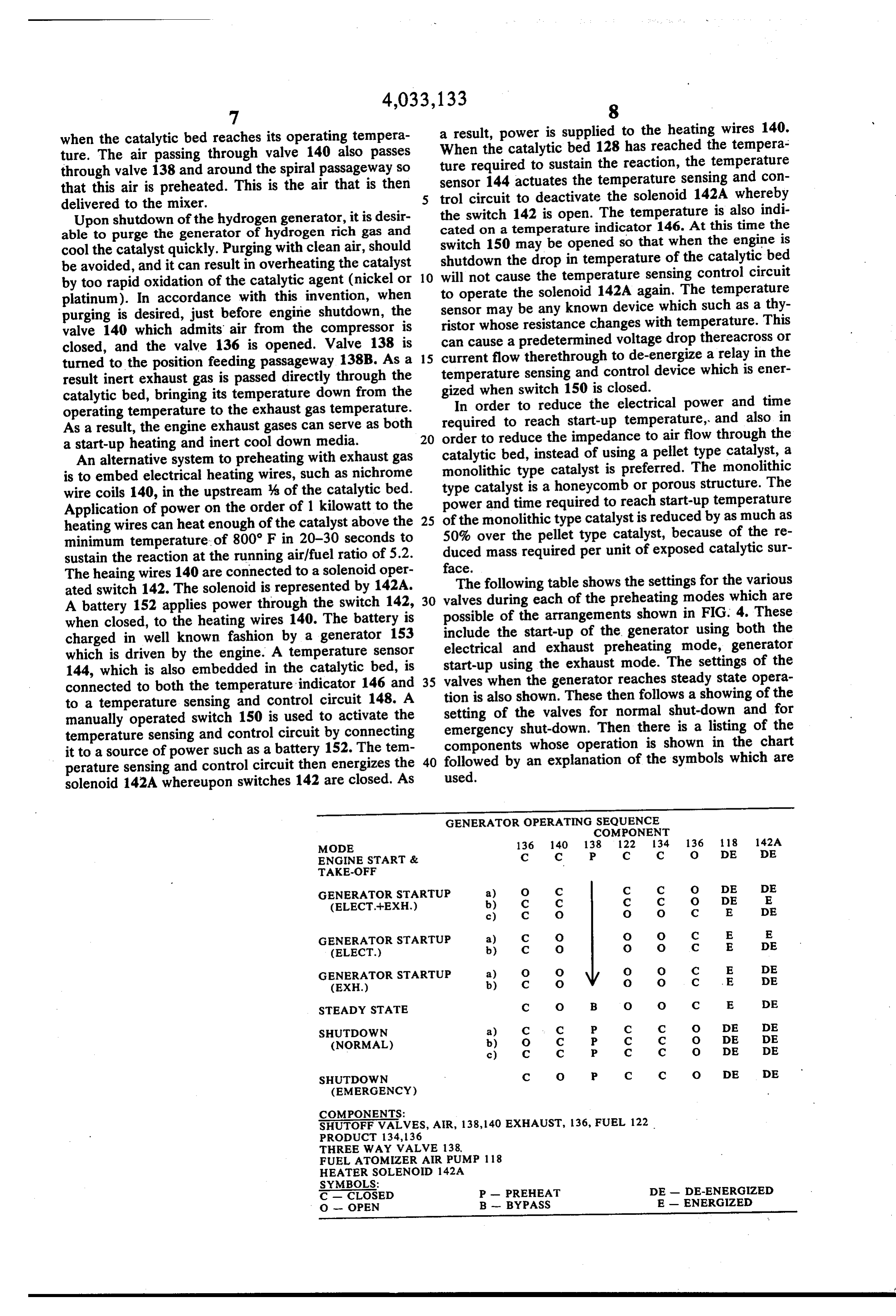
A battery 152 applies power through the switch 142, 30 valves during each of the preheating modes which are when closed, to the heating wires 140. The battery is possible of the arrangements shown in FIG. 4. These include the start-up of the generator using both the charged in well known fashion by a generator 153 electrical and exhaust preheating mode, generator which is driven by the engine. A temperature sensor start-up using the exhaust mode. The settings of the 144, which is also embedded in the catalytic bed, is connected to both the temperature indicator 146 and 35 valves when the generator reaches steady state opera to a temperature sensing and control circuit 148. A tion is also shown. These then follows a showing of the manually operated switch 150 is used to activate the setting of the valves for normal shut-down and for emergency shut-down. Then there is a listing of the temperature sensing and control circuit by connecting it to a source of power such as a battery 152. The tem 40 components whose operation is shown in the chart perature sensing and control circuit then energizes the followed by an explanation of the symbols which are solenoid 142A whereupon switches 142 are closed. As used.
GENERATOR OPERATING SEQUENCE
COMPONENT
MODE 136 1 40 138 122 134 136 118 142A
ENGINE START & C c P C C O DE DE
GENERATOR STARTUP a) O C C C O DE DE
(ELECT.--EXH.) b) C C C C O DE E
GENERATOR STARTUP a) C O O O C E E
(ELECT.) b) C O O O C E DE
GENERATOR STARTUP a) O O O O C E DE
(EXH.) b) C O O O C E DE
STEADY STATE C O B O O C E DE
SHUTDOWN a) C c P C C O DE DE
(NORMAL) b) O C P C C O DE DE
SHUTDOWN C O P C C O DE DE
(EMERGENCY)
COMPONENTS:
SHUTOFF VALVES, AIR, 138,140 EXHAUST, 136, FUEL 122
THREE WAY WALVE 138,
FUEL ATOMZERAIR PUMP 118
HEATER SOLENOID 142A
SYMBOLS:
C - CLOSED P - PREHEAT DE - DE-ENERGIZED
O - OPEN B - BYPASS E - ENERGIZED
Page 12
It will be noted that the engine start and take off In the case of engines which do not have turbines, the occurs first, thereafter there is a 3-step generator start override clutch 192 may be driven directly from the up process when a combined electrical and exhaust engine.
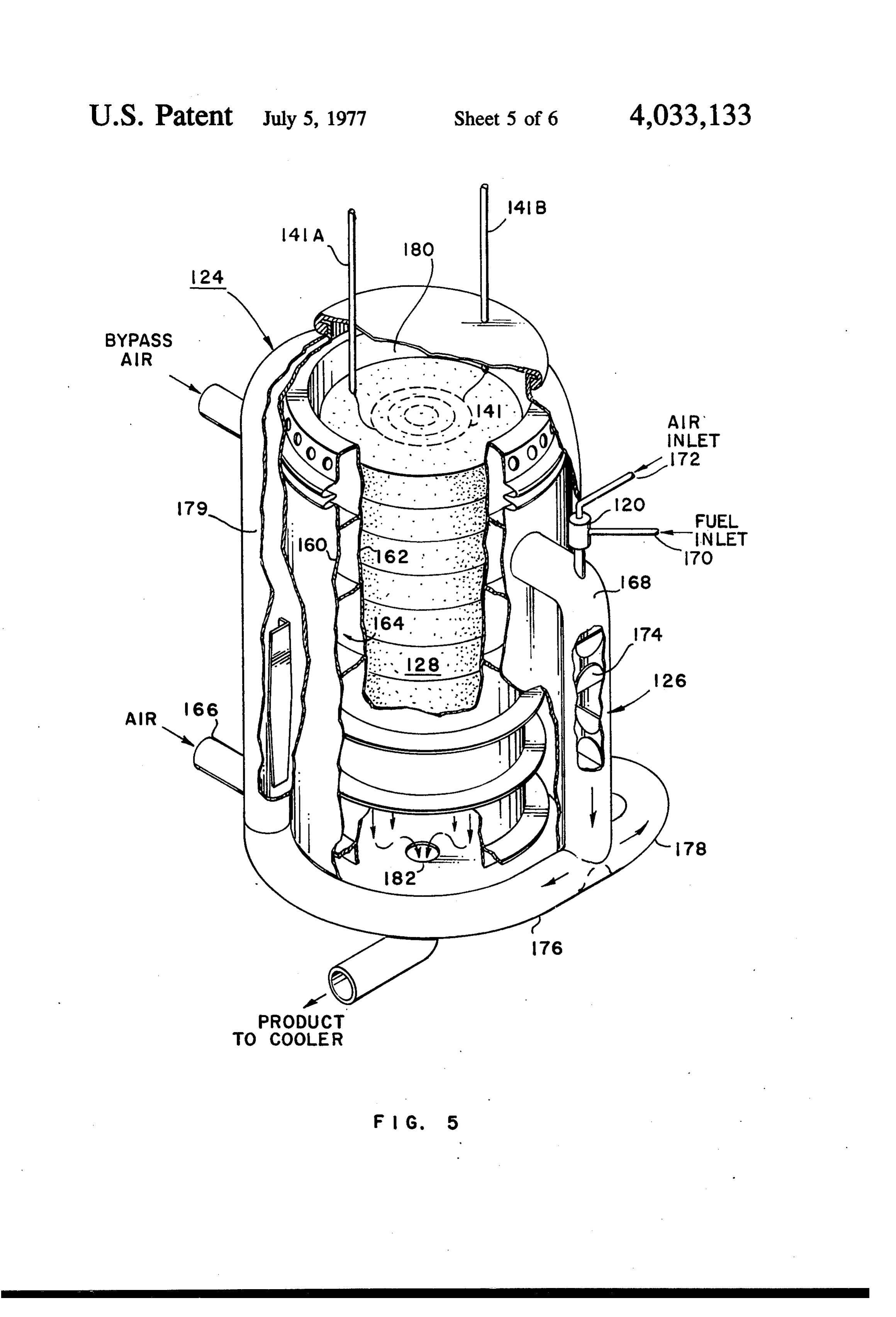
preheat process is used. A 2-step start-up is needed The advantages of the addition of a small turbine only when the electrical process is used. A 2-step start driven air compressor as shown in FIG. 6 are that it up is needed also only when the exhaust process is improves engine generator efficiency by eliminating used. A 3-step normal shutdown process is used also. the requirement for an engine driven air pump to sup As indicated previously, the valves can be solenoid ply air to the hydrogen generator at 10 psig, where operated and their opening and closing can be actuated there is not supercharger for the engine, and in those either manually or by automatic sequencing in re O cases where there is a supercharger, it eliminates the sponse to a stepper switch or electronic counter that is requirement for pumping the total air flow to a higher actuated either in response to catalytic bed tempera pressure, as required by the generator, whereas engine ture or time delay, or a combination of both. pressure requirements are significantly less. FIG. 5 is a drawing, in perspective and partially cut It enables an increase in the generator system operat away, of a hydrogen generator, in accordance with this 15 ing pressure level from 17 to 50 psia, which permits a invention. The parts of the generator which are similar reduction in generator size as a result of increased to the parts represented in FIG. 4 bear the same refer reactant density, and improves catalyst activity which is ence numerals. The electrical heating wires 140 are a fuction of operating pressure level. It also increases connected to two input terminals respectively 140A, the generator system efficiency by turbo-charger utili 140B. The top end of the chamber 124 is the input to 20 zation of 37% of the sensible heat in the generator the bed and the bottom end is the output 124. The product normally transferred to the engine cooling container includes an inner pair of walls respectively system by means of the product heat exchanger. 160, 162, with the catalytic bed 128 being adjacent to Thereby, a reduction in the size of coolant pumping the walls 162. A spiral passageway 164, is established power requirements for the hydrogen generator prod between the pair of walls, and incoming air exhaust 25 uct system is provided.
gases are directed from an inlet port 166 to the bottom While the description of the embodiments of the of the spiral passageway. It will flow upwardly along the invention are in connection with supercharged engines, catalytic bed, and will then flow out into a pipe which i.e. those using turbine driven air compressors, this not is part of the mixer 126. to be construed as a limitation on the invention since it At the top of this pipe is the fuel atomizer 120 with 30 is believed to be obvious to those skilled in the art how the two incoming pipes respectively 170, 172, serving this invention can be used with and for internal com as fuel inlet and air inlet pipes. The mixer pipes con bustion engines not having turbine driven air compres tains a plurality of baffles 174, which are disposed in a SOS.
manner to insure a through mixing of the air received There has accordingly been shown and described from the spiral passageway 164 with the atomized fuel 35 herein to insure vaporization of the atomized fuel. The air/fuel catalytica novel and useful system for startup heating the mixture then flows into two branching pipes respec energy developedabyhydrogen bed of
generator from heating internal combustion engine.
tively 176, 178, which lead into the passageway defined We claim:
between the wall 160 and an outer wall 179, which 1. In combination, an internal combustion engine, surrounds the entire generator, thus, insuring uniform 40 which produces hot exhaust gas when operative, and a flow to the catalytic bed. The passageway between the hydrogen product gas generator, walls leads into the input end or top end 180 of the said internal combustion engine having means for chamber 124 which adjacent the leading side of the applying an air/fuel mixture to said engine, and catalytic bed. The air/fuel mixture then passes through means attached to the engine for producing air the catalytic bed and then not through an exit port 182, 45 under pressure, to the cooler portion of the hydrogen generator, which said hydrogen product gas generator including is not shown here.
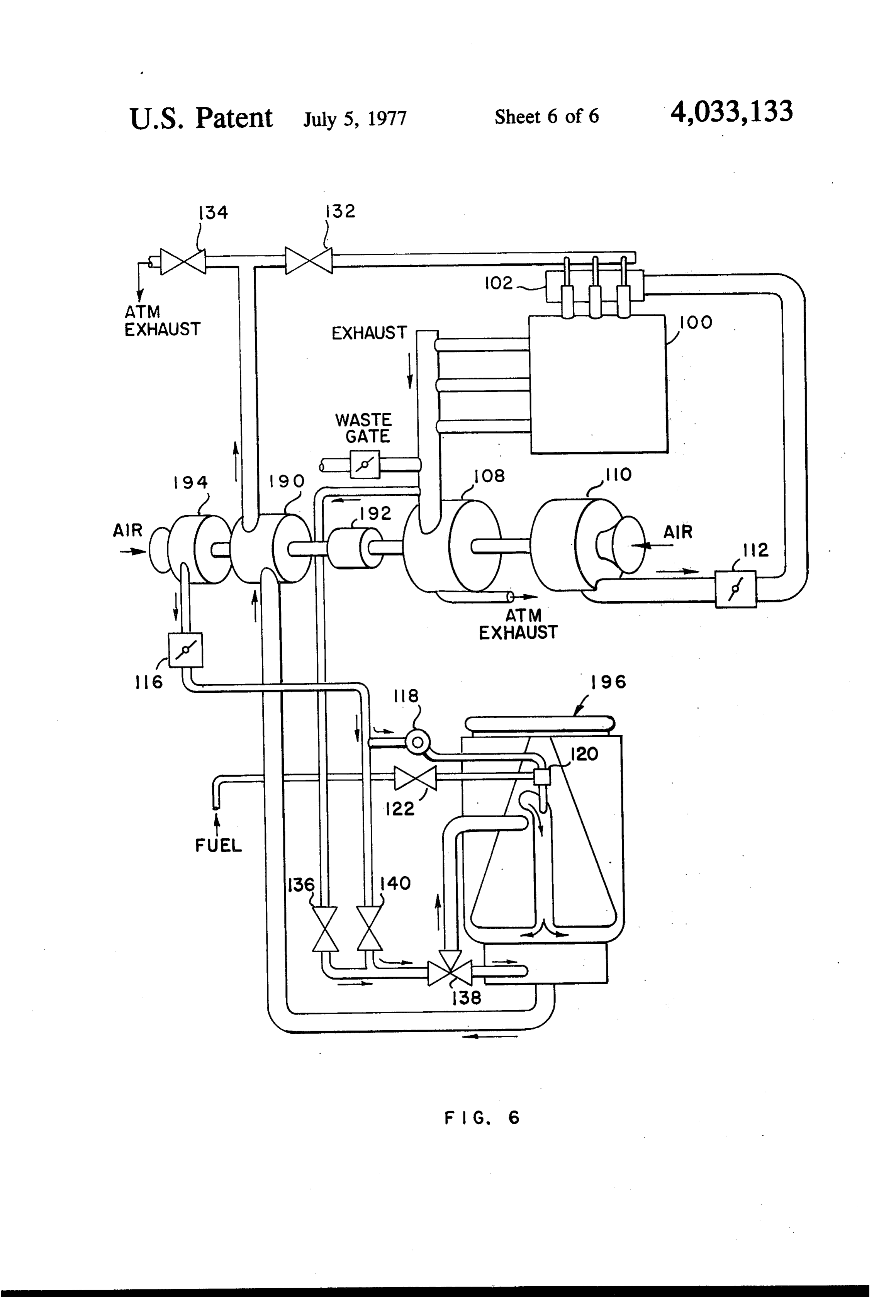
FIG. 6 is a schematic pictorialized drawing of a pre first walls defining a hollow chamber, said chamber ferred embodiment of the invention. It comprises a having an input end, an output end, and a center portion, modification of the arrangement represented by FIG. 4, 50 a catalytic or one of the preceding drawing figures, and therefore bed positioned in said center portion, structure having similar fuctions to the structures second walls forming a spiral passageway around said shown in FIG. 4 will bear the same reference numerals. first walls, said spiral passageway having an input The modification comprises the addition of a small end and an output end, turbine 190, which upon engine startup, is driven 55 fuel atomizer means having a fuel input, an atomizing air input, a vaporizing air input and output, through an overriding clutch 192 by the turbine 108 driven by the engine exhaust gas. The turbine 190 air/fuel mixer means having a first input connected to drives an air compressor 194 whose sole function is to said fuel atomizer output, a second input adjacent provide air for the hydrogen generator 196 and for sid first input connected to said spiral passageway driving the air atomizer booster pump. V 60 output end, and an output connecting to said hol The hydrogen generator outpt is first fed to the tur low chamber input end, bine 190 and after passing therethrough, is applied to first valve means having one position for permitting the atmospheric exhaust valve 134 and to the valve hot exhaust gas to be applied from said engine to determining feed of hydrogen product gas to the en said spiral passageway input end to thereby heat gine. When the hydrogen product gas becomes hot 65 the enclosed catalytic bed to an operating tempera enough to power the turbine i90, the turbine is driven ture, and a second position for blocking further gas by the hydrogen generator output and the drive from application, the turbine 108 is effectively disconnected. means defining a source of liquid hydrocarbon fuel,
Page 13
6. In combination, an second valve means having one position for applying which produces hot exhaust gas when internal combustion engine, fuel from said source to said fuel atomizer means operative, and a fuel input and a second position for blocking said hydrogen product gas generator, said internal combustion engine having means for fuel input, 5 applying an air/fuel mixture to said engine, and means for applying air from said means attached to means connected to the engine for producing air the engine to said fuel atomizer means atomizing under pressure, air input for atomizing fuel applied to said fuel said hydrogen product gas generator including atomizer means, first walls defining a hollow chamber, said chamber third valve means having a first position for applying O having an input end, an output end, and a center air from said means attached to the engine to said portion, spiral passageway input end and a second position a catalytic bed positioned in said center portion, for terminating the application of air, and heating wire means in said bed, fourth valve means having a first position for con 15 means for energizing said heating wire means to heat said catalytic bed to its operating temperature and necting said hollow chamber output end to said for de-energizing said heating wire means when it means for applying an air/fuel mixture to said en has reached its operating temperature, gine, and a second position for venting the hollow second walls forming a spiral passageway around said chamber output to the atmosphere whereby follow first wall, said spiral passageway having an input ing engine start up, said first valve means is placed 20 end and an output end, in its first position, said second, third and fourth fuel atomizer means having a fuel input, an atomizing valve means are placed in their second positions, air input, a vaporizing air input and an output, thereby hot engine exhaust gas can heat said cata air/fuel mixer means having a first input connected to lytic bed up to its operating temperature and then said fuel atomizer output, a second input adjacent be exhausted to the atmosphere, and upon the 25 said first input connected to said spiral passageway catalytic bed reaching its operating temperature, output end, and an output connecting to said hol said first valve means is placed in its second posi low chamber input end, tion and said second, third and fourth valve means means defining a source of liquid hydrocarbon fuel, are placed in their first positions whereby vapor 30 first valve means having a first position for applying fuel from said source to said fuel atomizer means ized hydrocarbon fuel and air are applied to said fuel input, and a second position for blocking said catalytic bed to produce a hydrogen rich product fuel input, gas which is applied to said engine. means for applying air from said engine to said fuel 2. In the combination recited in claim 1 wherein said atomizer means atomizing air input for atomizing means for applying an air/fuel mixture said engine in 35 fuel applied to said fuel atomizer means, cludes an intake manifold, and second valve means having a first position for apply said fourth valve means, when in its first position ing air from said engine to said spiral passageway connects said hollow chamber output end to said input end and a second position for terminating the intake manifold. application of air, and 3. In the combination recited in claim 1 wherein said 40 third valve means having a first position for connect catalytic bed is a monolithic catalytic bed. ing said hollow chamber output end to said means 4. In the combination recited in claim 1 wherein said for applying an air/fuel mixture to said engine, and means for producing air under pressure by said engine a second position for venting the hollow chamber comprises output to the atmosphere whereby following en gas driven turbine means including means for driving 45 gine start up, and after said catalytic bed has been heated to its operating temperature by said heating said turbine from said engine until it is gas driven, wire means, said first, second and third valve means for connecting said gas driven turbine means means are operated from their second to their first between said hollow chamber output end and said positions whereby the air from said engine is pre fourth valve means for driving said gas driven tur 50 heated by said catalytic bed vaporizes said atom bine means with the gas output from said hydrogen ized fuel and this is applied to said catalytic bed to generator and thereafter applying the gas output be converted to a hydrogen rich product gas which which has driven said turbine means to said fourth is fed to said means for applying an air/fuel mixture valve means, to said engine.
air compressor means driven by said gas driven tur 55 means 7. In the combination recited in claim 6 wherein said bine means, for applying an air/fuel mixture to said engine said means for applying air from said engine to said includes an intake manifold, and fuel atomizer means includes said third valve means when in its first position con means for applying output from said air compressor 60 nects said hollow chamber output to said intake manifold.
means to said fuel atomizer means, and 8. In the combination recited in claim 6 wherein said means for applying output from said air compressor catalytic bed is a monolithic catalytic bed. means to said third valve means. 9. In the combination recited in claim 6 wherein 5. In the combination recited in claim 1 wherein there is included:
there is included 65 means for purging said catalytic bed with hot exhaust means for purging said catalytic bed with hot exhaust gas for discontinuing the use of said hydrogen gas before discontinuing the use of said hydrogen product gas generator.
product gas generator.
Provenance
- Collection
- Cited prior art
- Original PDF
- patentimages.storage.googleapis.com →
- Filed
- 1976-03-22
- Pages
- 13
- Method
- pdftotext (the PDF's own text layer) + pdftoppm 300dpi page scans
- Source
- Google Patents bibliographic record
- Granted
- 1977-07-05
- Inventors
- John Houseman; Donald J. Cerini; California Institute of Technology
- Transcribed from
- patentimages.storage.googleapis.com →