patent · US3310483
Multicell oxyhydrogen generator
21 March 1967
Page 1
Drawing sheet — no readable text.
Page 2
United States Patent Office Patented Mar.3,310,483
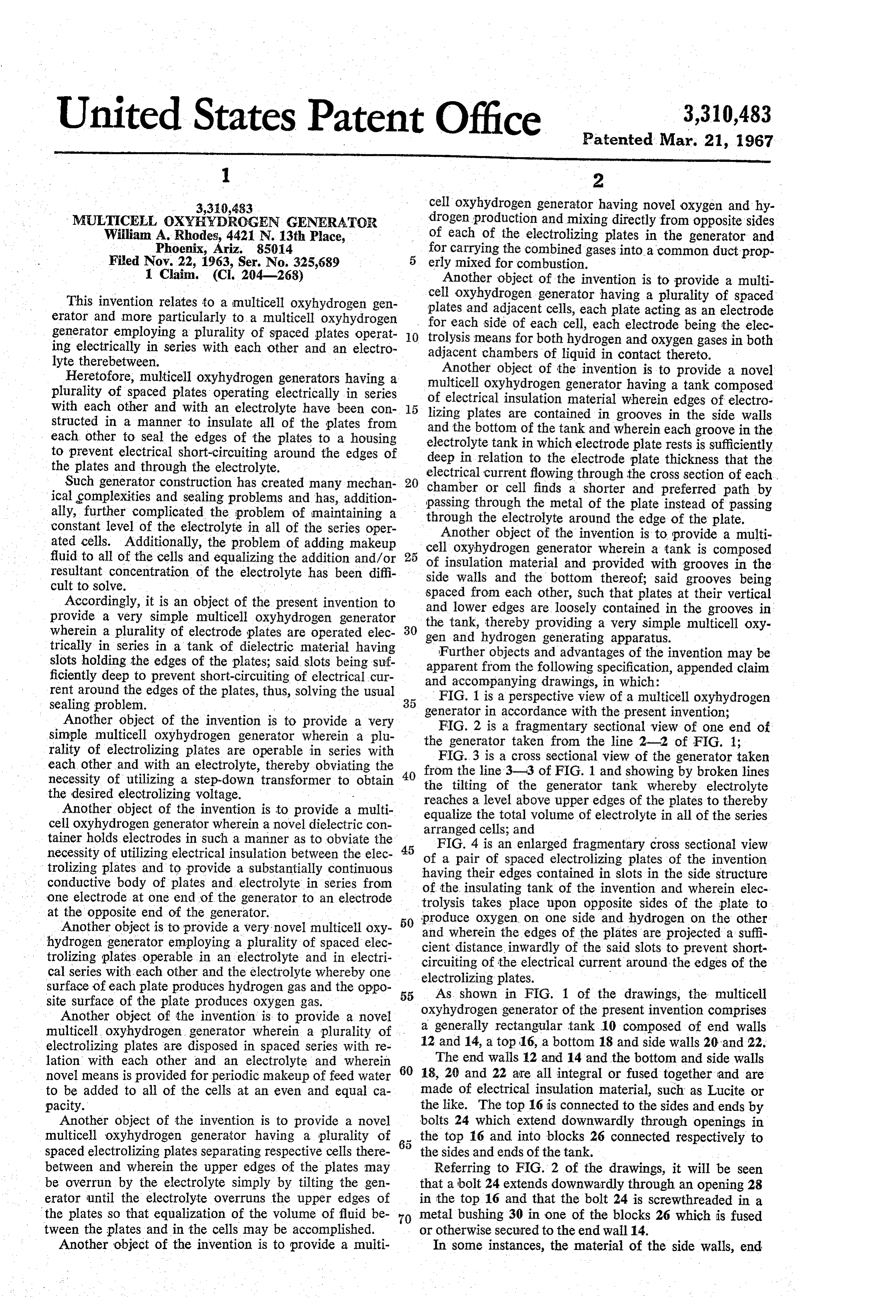
3,310,483 cell oxyhydrogen generator having novel oxygen and hy MULTICELL, OXYHYDROGEN GENERATOR drogen production and mixing directly from opposite sides William A. Rhodes, 4421 N. 13th Place, of each of the electrolizing plates in the generator and Phoenix, Ariz. 85014 for carrying the combined gases into a commonduct prop Filed Nov. 22, 1963, Ser. No. 325,689 erly mixed for combustion.
1. Claim. (CI. 204-268) Another object of the invention is to provide a multi cell oxyhydrogen generator having a plurality of spaced
This invention relates to a multicell oxyhydrogen gen plates erator and more particularly to a multicell oxyhydrogen and adjacent cells, each plate acting as an electrode for each side of each cell, each electrode being the elec generator employing a plurality of spaced plates operat O trolysis means ing electrically in series with each other and an electro for both hydrogen and oxygen gases in both lyte therebetween. adjacent chambers of liquid in contact thereto. Another object of the invention is to provide a novel
Heretofore, multicell oxyhydrogen generators having a multicell plurality of spaced plates operating electrically in series oxyhydrogen generator having a tank composed with each other and with an electrolyte have been con of electrical insulation material wherein edges of electro lizing plates are contained in grooves in the side walls structed in a manner to insulate all of the plates from and the bottom of the tank and wherein each groove in the each other to seal the edges of the plates to a housing electrolyte tank in which electrode plate rests is sufficiently to prevent electrical short-circuiting around the edges of deep in relation to the electrode plate thickness that the the plates and through the electrolyte.
Such generator construction has created many mechan chamber or cell flowing
electrical current through the cross section of each.
ical gomplexities and sealing problems and has, addition passing through the metalshorter finds a of the and preferred path by plate instead of passing ally, further complicated the problem of maintaining a constant level of the electrolyte in all of the series oper through the electrolyte around the edge of the plate. ated cells. Additionally, the problem of adding makeup cellAnother object of the invention is to provide a multi oxyhydrogen generator wherein a tank is composed fluid to all of the cells and equalizing the addition and/or 25 of insulation material and provided with grooves in the resultant concentration of the electrolyte has been diffi side walls and the bottom thereof; said grooves being
Accordingly, it is an object of the present invention to spaced from each other, Such that plates at their vertical provide a very simple multicell oxyhydrogen generator the and lower edges are loosely contained in the grooves in wherein a plurality of electrode plates are operated elec 30 gen tank,and thereby providing a very simple multicell oxy hydrogen generating apparatus.
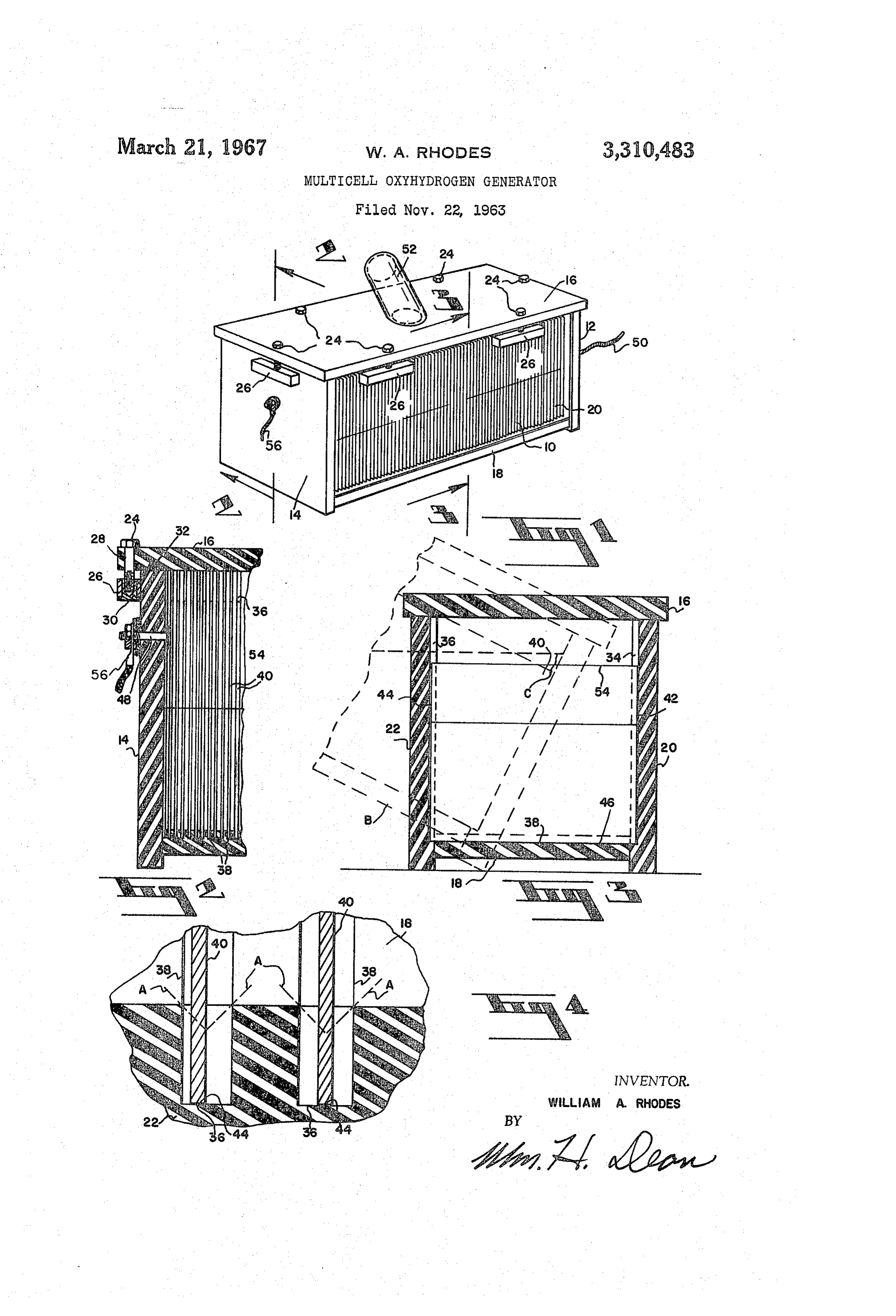
trically in series in a tank of dielectric material having Further objects and advantages of the invention may be slots holding the edges of the plates; said slots being suf apparent from the following specification, appended claim ficiently deep to prevent short-circuiting of electrical cur and accompanying drawings, in which: rent around the edges of the plates, thus, solving the usual FIG. 1 is a perspective view of a multicell oxyhydrogen sealing problem. 35 generator in accordance with the present invention;
Another object of the invention is to provide a very simple multicell oxyhydrogen generator wherein a plu theFIG. 2 is a fragmentary sectional view of one end of generator taken from the line 2-2 of FIG. 1;
rality of electrolizing plates are operable in series with FIG. 3 is a cross sectional view of the generator taken each other and with an electrolyte, thereby obviating the 40 from the line 3-3 of FIG. 1 and showing by broken lines necessity of utilizing a step-down transformer to obtain the tilting of the generator tank whereby electrolyte the desired electrolizing voltage. - reaches a level above upper edges of the plates to thereby Another object of the invention is to provide a multi equalize the total volume of electrolyte in all of the series cell oxyhydrogen generator wherein a novel dielectric con arranged cells; and tainer holds electrodes in such a manner as to obviate the FIG. 4 is an enlarged fragmentary cross sectional view necessity of utilizing electrical insulation between the elec 45 trolizing plates and to provide a substantially continuous having of a pair of spaced electrolizing plates of the invention conductive body of plates and electrolyte in series from of the insulating their edges contained in slots in the side structure one electrode, at one end of the generator to an electrode tank of the invention and wherein elec at the opposite end of the generator. trolysis takes place upon opposite sides of the plate to Another object is to provide a very novel multicell oxy 50 and produce oxygen on one side and hydrogen on the other hydrogen generator employing a plurality of spaced elec cientwherein the edges of the plates are projected a suffi trolizing plates operable in an electrolyte and in electri circuiting of theinwardly distance of the said slots to prevent short electrical current around the edges of the cal series with each other and the electrolyte whereby one electrolizing plates.
surface of each plate produces hydrogen gas and the oppo 55 As shown in FIG. 1 of the drawings, the multicell site surface of the plate produces oxygen gas.
Another object of the invention is to provide a novel oxyhydrogen a generally generator of the present invention comprises rectangular tank 10 composed of end walls multicell oxyhydrogen generator wherein a plurality of electrolizing plates are disposed in spaced series with re 12 and 14, a top 16, a bottom 18 and side walls 20 and 22. lation with each other and an electrolyte and wherein The end walls 12 and 14 and the bottom and side walls novel means is provided for periodic makeup of feed water 60 18, 20 and 22 are all integral or fused together and are to be added to all of the cells at an even and equal ca made of electrical insulation material, such as Lucite or pacity. the like. The top 16 is connected to the sides and ends by Another object of the invention is to provide a novel bolts 24 which extend downwardly through openings in multicell oxyhydrogen generator having a plurality of the top 16 and into blocks 26 connected respectively to spaced electrolizing plates separating respective cells there the sides and ends of the tank.
between and wherein the upper edges of the plates may Referring to FIG. 2 of the drawings, it will be seen be overrun by the electrolyte simply by tilting the gen that a bolt 24 extends downwardly through an opening 28 erator until the electrolyte overruns the upper edges of in the top 16 and that the bolt 24 is screwthreaded in a the plates so that equalization of the volume of fluid be 70 metal bushing 30 in one of the blocks 26 which is fused tween the plates and in the cells may be accomplished. or otherwise secured to the end wall 14. Another object of the invention is to provide a multi In some instances, the material of the side walls, end
Page 3
walls and bottom, may be Lucite or other equivalent in the upper edges 54 of the plates 40. The electrolyte is disposed in the tank below the upper edges 54 of the plates
Sulating material forming a float type container. and the level of the electrolyte in the tank may be varied The cover 16 is provided with a recessed gasket 32 to vary the effective area of the plates which correspond which bears on the upper edges of the side and end walls, ingly relates to power consumption and the amount of as shown in FIG. 2 of the drawings, to provide a gas seal gas yield of the generator.
at the upper end of the tank. When it is desired to add makeup water, it may be The side walls 20 and 22 are provided with spaced slots poured through the conduit 52 and the tank may be tilted 34 and 36, as shown on the enlarged scale in FIG. 4 as indicated by broken lines B in FIG. 3 of the drawings, of the drawings. The bottom 18 is provided with similar slots 38, these slots as shown in FIG. 2 of the drawings, IO So that the electrolyte level is disposed at C above upper edges 54 of the titled plates 40. Thus, the electrolyte are spaced from each other and electrolizing plates 40 are provided with edges 42, 44 and 46 disposed respectively volume equalized.
between each adjacent plate and in each cell is in the slots 34, 36 and 38 of the sides 20 and 22 and the The generator of the present invention when operated bottom 18. produces hydrogen and oxygen gas from opposite sides The slots 34, 36 and 38 are all of substantially similar of each of the plates 40 and these gases rise and mix in depth and correspond structurely to the description which timately at the upper edges 54 of the plates and may be will be hereinafter made in connection with FIG. 4 of the drawings. carried outwardly through the conduit 52 or any other As an example, the plates may be eighteen thousandths 20 suitable conduit to a use location, such as a torch or other of an inch thick and the slots may be 32 thousandths of combustion means.
It will be obvious to those skilled in the art that various an inch wide. These dimensions may be varied in propor modifications of the present invention may be resorted to tion to the size of the apparatus required and are only in a manner limited only by a just interpretation of the given by way of an example.
The plates 40 may be any suitable material known in 25 following I claim:
claim.
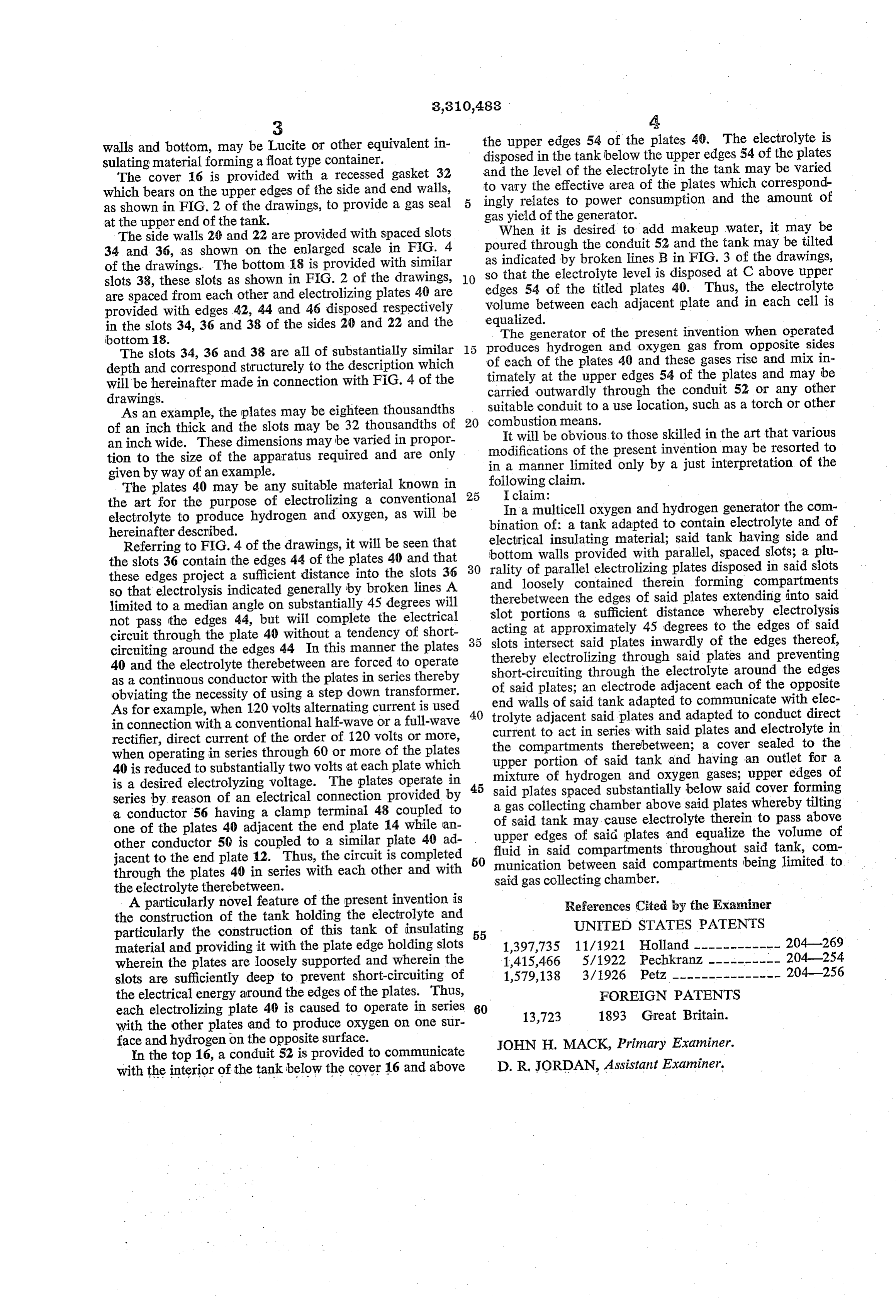
the art for the purpose of electrolizing a conventional In a multicell oxygen and hydrogen generator the com electrolyte to produce hydrogen and oxygen, as will be bination of: a tank adapted to contain electrolyte and of hereinafter described. electrical insulating material; said tank having side and Referring to FIG. 4 of the drawings, it will be seen that the slots 36 contain the edges 44 of the plates 40 and that 30 bottom rality of walls provided with parallel, spaced slots; a plu parallel electrolizing plates disposed in said slots these edges project a sufficient distance into the slots 36 and loosely contained therein forming compartments so that electrolysis indicated generally by broken lines A therebetween the edges of said plates extending into said limited to a median angle on substantially 45 degrees will slot portions a sufficient distance whereby electrolysis not pass the edges 44, but will complete the electrical acting at approximately 45 degrees to the edges of said circuit through the plate 40 without a tendency of short 35 slots intersect said plates inwardly of the edges thereof, circuiting around the edges 44. In this manner the plates thereby electrolizing through said plates and preventing 40 and the electrolyte therebetween are forced to operate short-circuiting through the electrolyte around the edges as a continuous conductor with the plates in series thereby of said plates; an electrode adjacent each of the opposite obviating the necessity of using a step down transformer. end walls of said tank adapted to communicate with elec As for example, when 120 volts alternating current is used 40 trolyte adjacent said plates and adapted to conduct direct in connection with a conventional half-wave or a full-wave current to act in series with said plates and electrolyte in rectifier, direct current of the order of 120 volts or more, when operating in series through 60 or more of the plates the upper compartments therebetween; a cover sealed to the portion of said tank and having an outlet for a 40 is reduced to substantially two volts at each plate which mixture of hydrogen and oxygen gases; upper edges of is a desired electrolyzing voltage. The plates operate in said plates spaced substantially below said cover forming series by reason of an electrical connection provided by a gas collecting chamber above said plates whereby tilting a conductor 56 having a clamp terminal 48 coupled to of said tank may cause electrolyte therein to pass above one of the plates 40 adjacent the end plate 14 while an other conductor 50 is coupled to a similar plate 40 ad upper edges of said plates and equalize the volume of jacent to the end plate 12. Thus, the circuit is completed 50 fluid in said compartments throughout said tank, com munication between said compartments being limited to through the plates 40 in series with each other and with said gas collecting chamber.
the electrolyte therebetween.
A particularly novel feature of the present invention is References Cited by the Examiner the construction of the tank holding the electrolyte and UNITED STATES PATENTS particularly the construction of this tank of insulating 55 material and providing it with the plate edge holding slots 1,397,735 11/1921 Holland ------------ 204-269 wherein the plates are loosely supported and wherein the 1,415,466 5/1922 Pechkranz --------- 204-254 slots are sufficiently deep to prevent short-circuiting of 1,579,138 3/1926 Petz --------------- 204-256 the electrical energy around the edges of the plates. Thus, FOREIGN PATENTS each electrolizing plate 40 is caused to operate in series 60 13,723 1893 Great Britain. with the other plates and to produce oxygen on one sur face and hydrogen on the opposite surface. JOHN H. MACK, Primary Examiner.
In the top 16, a conduit 52 is provided to communicate with the interior of the tank below the cover 16 and above D. R. JORDAN, Assistant Examiner.
Provenance
- Collection
- Cited prior art
- Original PDF
- patentimages.storage.googleapis.com →
- Filed
- 1963-11-22
- Pages
- 3
- Method
- pdftotext (the PDF's own text layer) + pdftoppm 300dpi page scans
- Source
- Google Patents bibliographic record
- Granted
- 1967-03-21
- Inventors
- William A Rhodes
- Transcribed from
- patentimages.storage.googleapis.com →