patent · US5272871
Method and apparatus for reducing nitrogen oxides from internal combustion engine
28 December 1993
Page 1 — bibliographic record
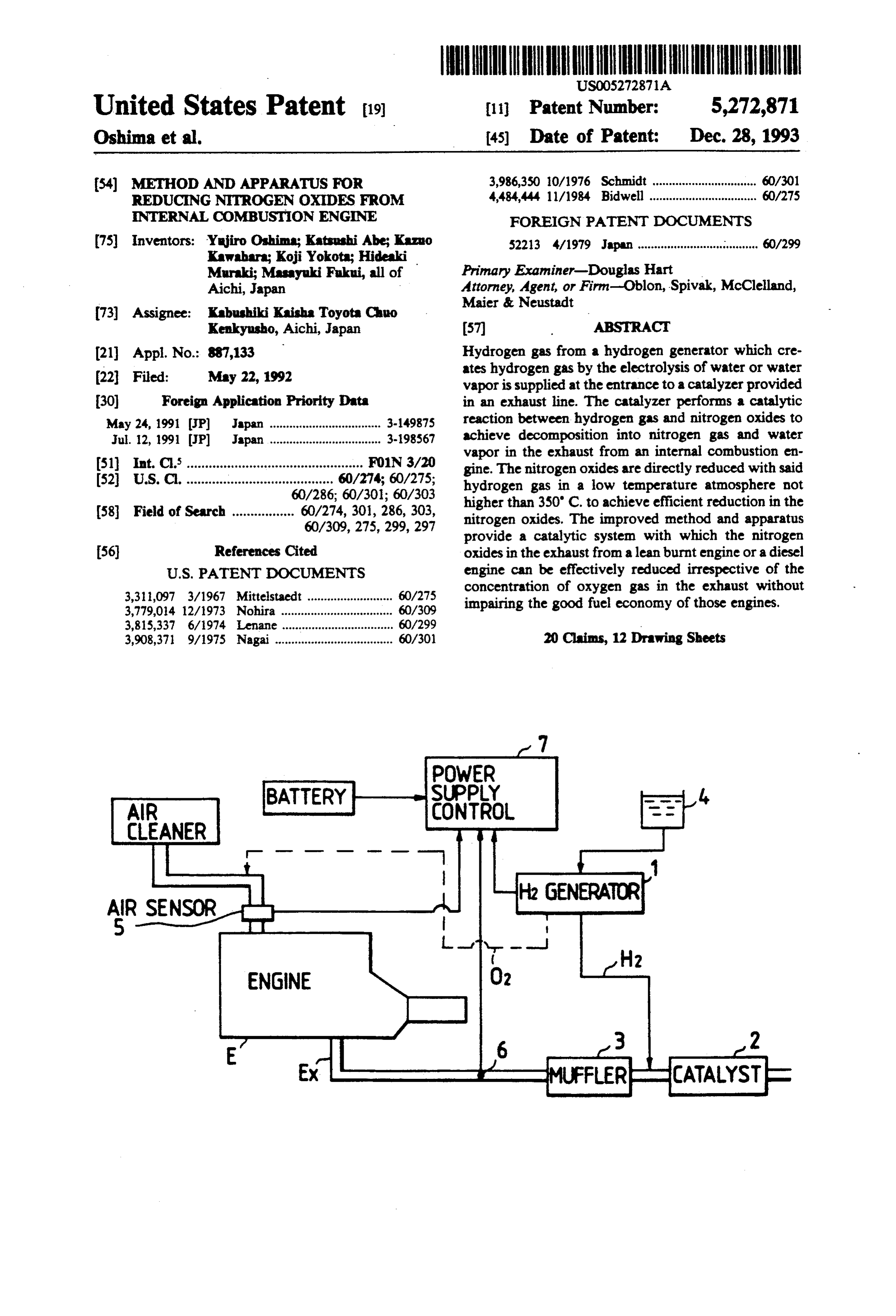
United States Patent (19) 11 Patent Number: 5,272,871 Oshima et al. - (45) Date of Patent: Dec. 28, 1993 (54) METHOD AND APPARATUS FOR 3,986,350 10/1976 Schmidt ................................ 60/301 REDUCING NTROGEN OXDES FROM 4,484,444 11/1984 Bidwell ................................. 60/275 NTERNAL COMBUSTON ENGINE FOREIGN PATENT DOCUMENTS 75) Inventors: Yujiro Oshima; Katsushi Abe; Kazuo 52213 4/1979 Japan ..................................... 60/299 Kawahara; Koji Yokota; Hideaki Primary Examiner-Douglas Hart
Muraki; Masayuki Fukui, all of
Aichi, Japan Attorney, Agent, or Firm-Oblon, Spivak, McClelland, Maier & Neustadt 73) Assignee: Kabushiki Kaisha Toyota Chuo
Kenkyusho, Aichi, Japan 57 ABSTRACT (21) Appl. No.: 887,133 Hydrogen gas from a hydrogen generator which cre (22 Filed: May 22, 1992 ates hydrogen gas by the electrolysis of water or water vapor is supplied at the entrance to a catalyzer provided 30 Foreign Application Priority Data in an exhaust line. The catalyzer performs a catalytic May 24, 1991 JP Japan .................................. 3-149875 reaction between hydrogen gas and nitrogen oxides to Jul. 12, 1991 JP Japan .................................. 3-198567 achieve decomposition into nitrogen gas and water vapor in the exhaust from an internal combustion en 51 int. C. ................................................ FO1N3/20 gine. The nitrogen oxides are directly reduced with said 52 U.S. C. ........................................ 60/274; 60/275; hydrogen gas in a low temperature atmosphere not 60/286; 60/301; 60/303 higher than 350' C. to achieve efficient reduction in the 58 Field of Search ................. 60/274, 301, 286, 303, nitrogen oxides. The improved method and apparatus 60/309, 275,299,297 provide a catalytic system with which the nitrogen (56) References Cited oxides in the exhaust from a lean burnt engine or a diesel
3,311,097 3/1967 Mittelstaedt .......................... 60/275 concentration of oxygen gas in the exhaust without 3,779,014 12/1973 Nohira . 60/309 impairing the good fuel economy of those engines. 3,815,337 6/1974 Lenane. 60/299 3,908,371 9/1975 Nagai .................................... 60/30 20 Claims, 12 Drawing Sheets
CLEANER
AR SENSOR
CATALYST
Page 2
Drawing sheet — no readable text.
Page 3
Drawing sheet — no readable text.
Page 4
Drawing sheet — no readable text.
Page 5
Drawing sheet — no readable text.
Page 6
Drawing sheet — no readable text.
Page 7
Drawing sheet — no readable text.
Page 8
Drawing sheet — no readable text.
Page 9
Drawing sheet — no readable text.
Page 10
Drawing sheet — no readable text.
Page 11
avas was a tarysva. Yar 8 yaraa as Y O 67 O N-O O O E asvava as why ava w x s as was waves a sa s. n
cascareer rvantayamvara
CAALYST
Page 12
Drawing sheet — no readable text.
Page 13
Drawing sheet — no readable text.
Page 14
satisfactory reduction in NOx content while using an
METHOD AND APPARATUS FOR REDUCNG air/fuel ratio that is capable of achieving maximum NTROGEN OXDES FROM INTERNAL improvement in the fuel economy of the engine has COMBUSTON ENGINE many problems to be solved before they are put to practical use.
BACKGROUND OF THE INVENTION
SUMMARY OF THE INVENTION
This invention relates to a method and apparatus for reducing the content of nitrogen oxides from internal The present invention has been accomplished under combustion engines. More specifically, the invention O these circumstances and has as an object providing a relates to a system for cleaning up lean burnt exhaust method for reducing nitrogen oxides in exhaust gases that is applicable to a "lean burnt engine' which uses a from an internal combustion engine, which method is dilute air-fuel mixture with a view to improving fuel capable of suppressing the release of NOx. economy, as well as a diesel engine, a hydrogen engine Another object of the present invention is to provide and a Stirling engine (the last-mentioned is an external 5 an apparatus for reducing nitrogen oxides in exhaust combustion engine) and which is capable of effectively gases from an internal combustion engine, which appa reducing and cleaning up nitrogen oxides (hereunder ratus is also capable of suppressing the release of NOX. sometimes abbreviated as NOx) in the exhaust irrespec The method and apparatus of the present invention tive of its concentration of oxygen gas (hereunder some provide a catalytic exhaust system with which the NOx times abbreviated as O2) without impairing the good in the exhaust from a lean burnt engine or a diesel en fuel economy of those engines.
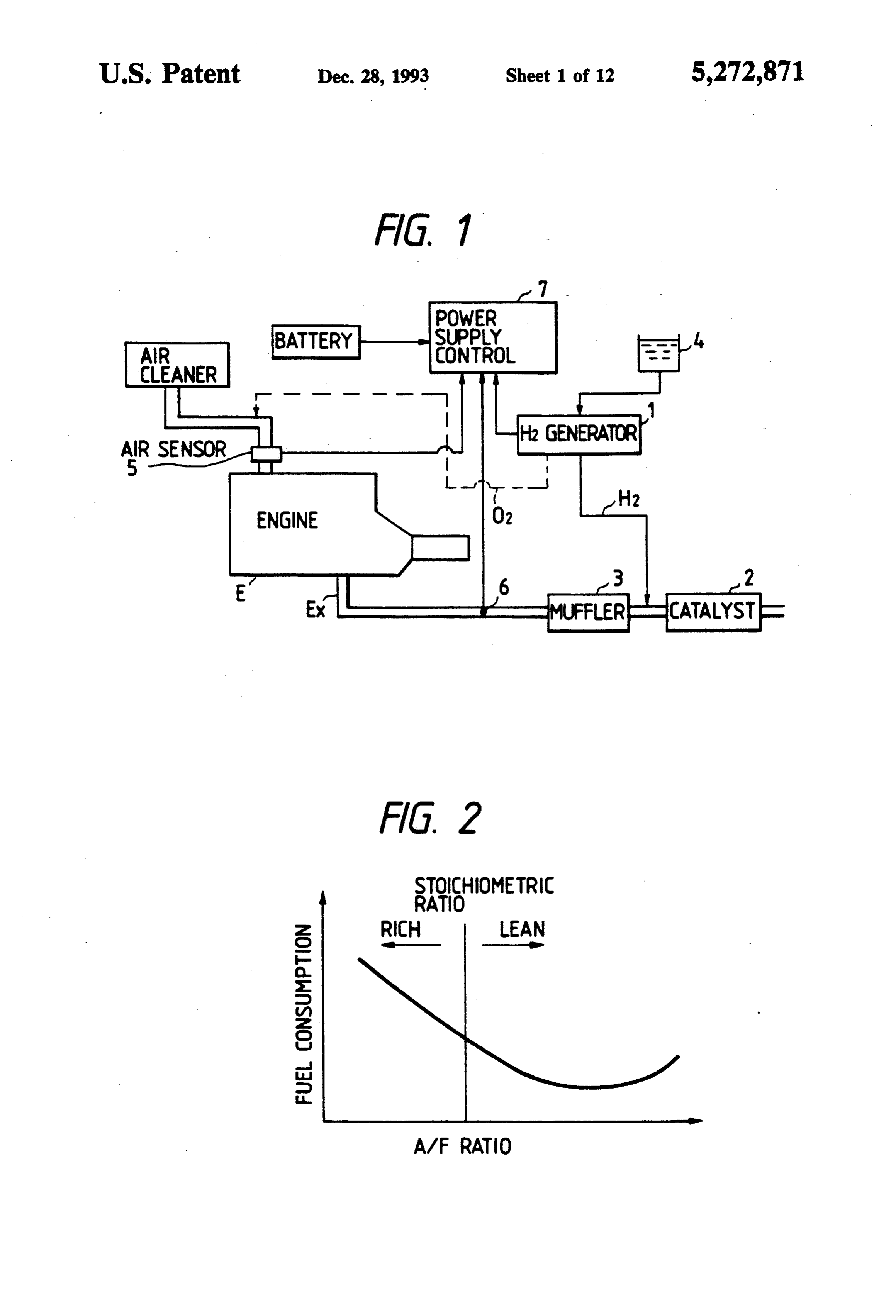
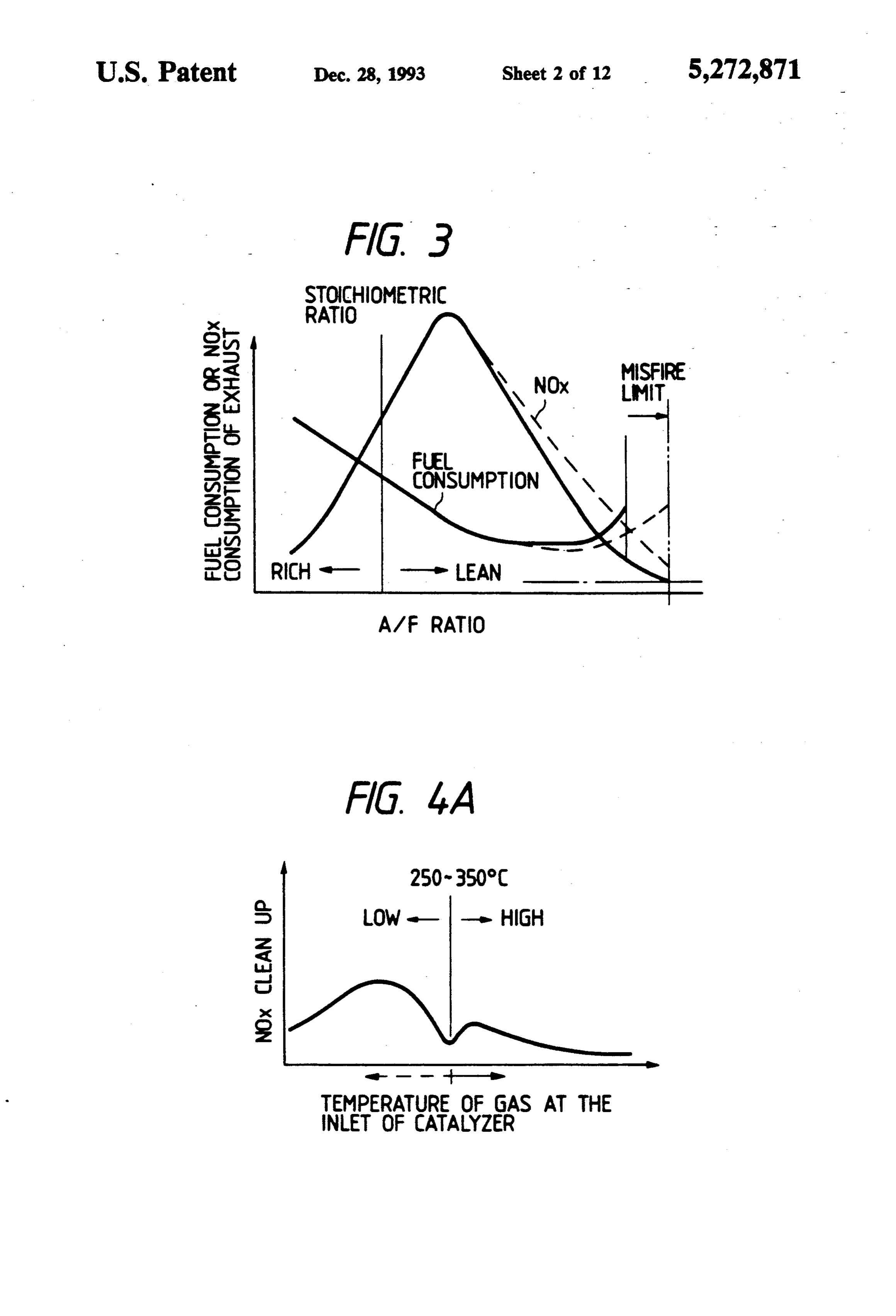
Conventionally, three methods have been proposed gine which always operates on the oxygen (air)-rich as means of reducing the content of NOx in the exhaust side can be effectively reduced and cleaned up in the presence of both NOx and O2 in the exhaust irrespective from internal-combustion engines, principally piston of the concentration of O2 in the exhaust without in engines and they are: pairing the good fuel economy of either type of engines. (1) use of a three-way catalyst; 25 (2) use of an ultra-lean air/fuel ratio; and The method of the present invention for reducing (3) use of a lean NOx catalyst. nitrogen oxides in exhaust gases from an internal com These methods have their own disadvantages. The bustion engine, comprises a step of supplying a hydro first method requires that the air and fuel mixture to be gen gas from a hydrogen generator for mixing into supplied to the engine should be precisely controlled to exhaust gases including nitrogen oxides and oxygen gas the stoichiometric air/fuel ratio (ca. 14.5:1). If the fuel is at an upstream position of a catalyzer provided in an leaner than the stoichiometric ratio, the content of NOx exhaust line, said hydrogen generator producing said is not reduced. However, it is known that fuel economy hydrogen gas by electrolysis of water or water vapor is promoted by operating the engine on the fuel-lean and said catalyzer causing a catalytic reaction between side as shown in FIG. 2. The second method is intended 35 the hydrogen gas and nitrogen oxides to decompose to achieve both lower NOx content and better fuel into nitrogen gas and water vapor, and a step of directly economy with a "lean burnt engine'. However, if one reducing said nitrogen oxides in said exhaust gases with wants to use an air/fuel ratio that is capable of satisfac said hydrogen gas under a low temperature atmosphere tory reduction in the NOx content, the fuel-air mixture of not higher than 350° C.
approaches the misfire limit of combustion and this The apparatus of the present invention for reducing deteriorates not only the fuel economy of the engine but nitrogen oxides in exhaust gases including nitrogen also the drivability of the vehicle. In order to avoid oxides and an oxygen gas from an internal combustion these problems, methods have been proposed by which engine, said apparatus comprises: a hydrogen generator the air stream in the cylinder is provided with turbu for producing the hydrogen gas by the electrolysis of lence or increased in flow rate so that the combustion 45 water or water vapor, thereby supplying said hydrogen speed is sufficiently increased to bring the misfire limit gas into said exhaust gases at an upstream position of to a further fuel-lean side. However, this is not expected said catalyzer; and a catalyzer for reducing said nitro to achieve a satisfactory effect because if the misfire limit is brought to a further fuel-lean side (see FIG. 3), gen oxides into a nitrogen gas and water vapor by a catalytic reaction between a hydrogen gas and nitrogen the NOx emission will decrease by a smaller degree as oxides, said indicated by the dashed line. To compensate for these whereby saidcatalyzer being provided in an exhaust line; problems of the second method, it has been proposed by said hydrogen gas fromoxides nitrogen said are directly reduced with hydrogen generator under the third method that the engine be operated at an air/f. a low temperature atmosphere of not higher than 350 uel ratio that is near the point where the fuel consump C.
tion is at minimum, which point is somewhat closer to 55 the stoichiometric ratio than the misfire limit. The NOx BRIEF DESCRIPTION OF THE DRAWINGS whose content tends to decrease by an insufficient de FIG. 1 is a block diagram showing the basic layout of gree in the second method is cleaned up with a zeolite the system of the present invention for reducing nitro based lean NOx catalyst in the third method. This ap proach can potentially provide a system of better fuel gen oxides in an internal combustion engine; economy. However, the lean NOx catalyst which re FIG. 2 is a graph showing the relationship between duces NOx in the presence of a large amount of O2 in air/fuel ratio and fuel economy;
the exhaust is required to meet strict temperature and FIG. 3 is a graph showing the relationship between other conditions and this presents one major practical the fuel economy of a lean burnt engine and NOx; problem to be solved in that it is difficult to achieve 65 FIG. 4A is a graph showing a characteristic of a lean satisfactory catalytic of NOx while using the catalyst NOx catalyst;
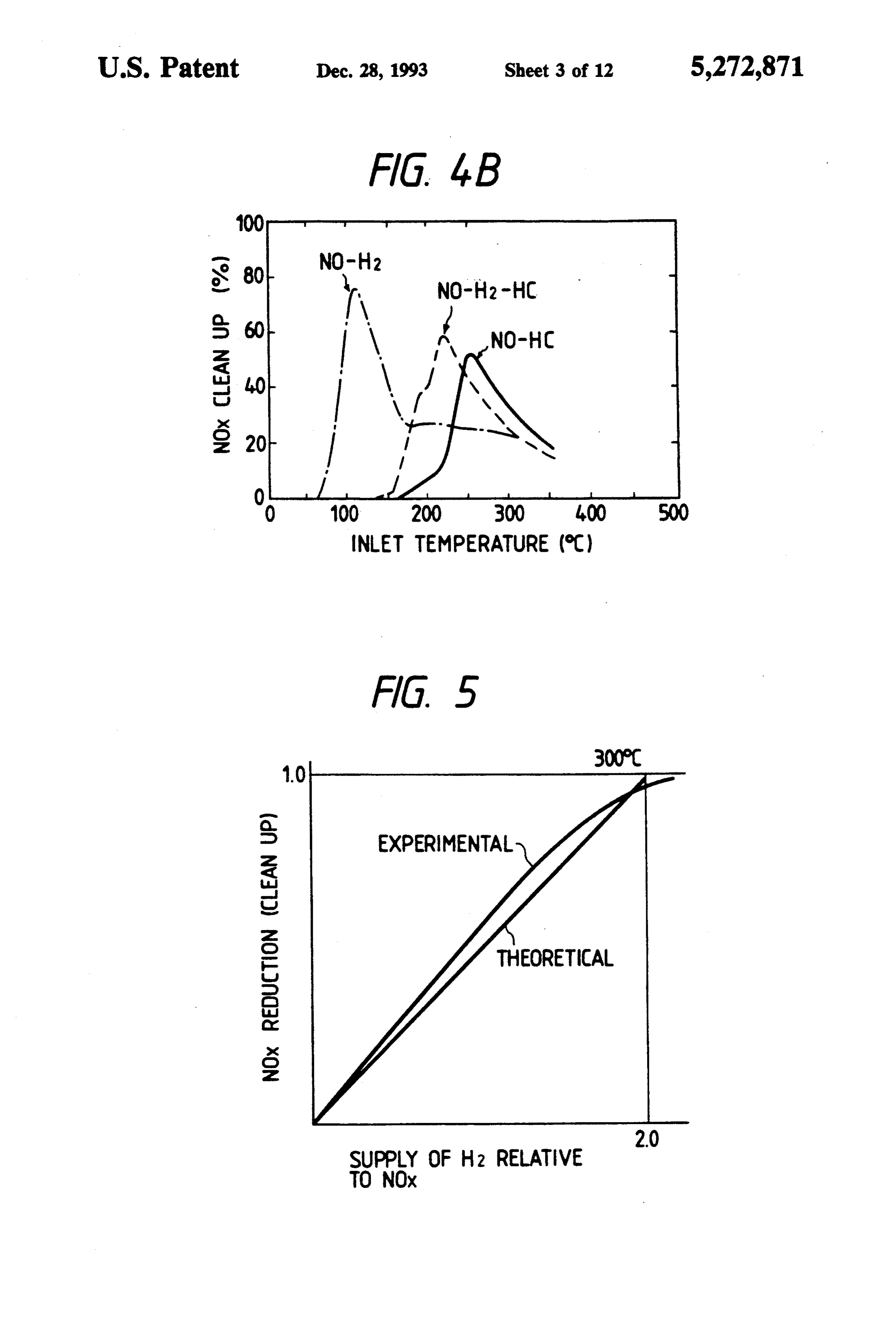
over an extended period (high catalyst durability). FIG. 4B is a graph showing another characteristic of Thus, each of the methods so far proposed for achieving a lean NOx catalyst;
Page 15
FIG. 5 is a graph showing the relationship between FIG. 28 is a block diagram showing the basic layout the relative supply of H2 and the relative cleanup of of the apparatus according to the tenth embodiment of NOx; the present invention.
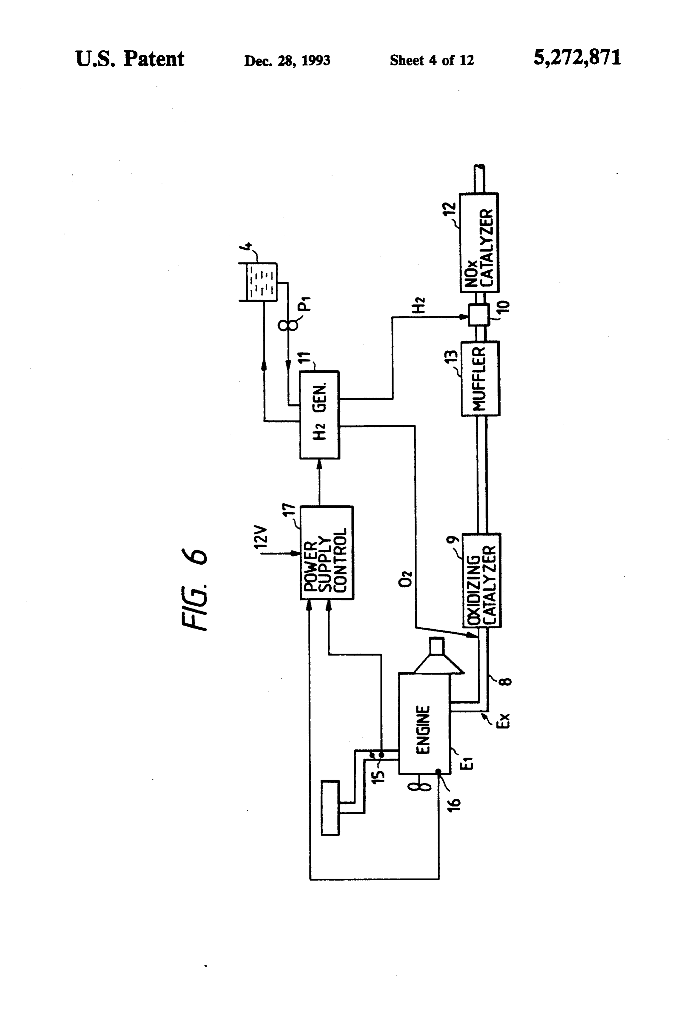
FIG. 6 is a block diagram showing the basic layout of DETALED DESCRIPTION OF THE an apparatus according to the first embodiment of the 5 NVENTION present invention;
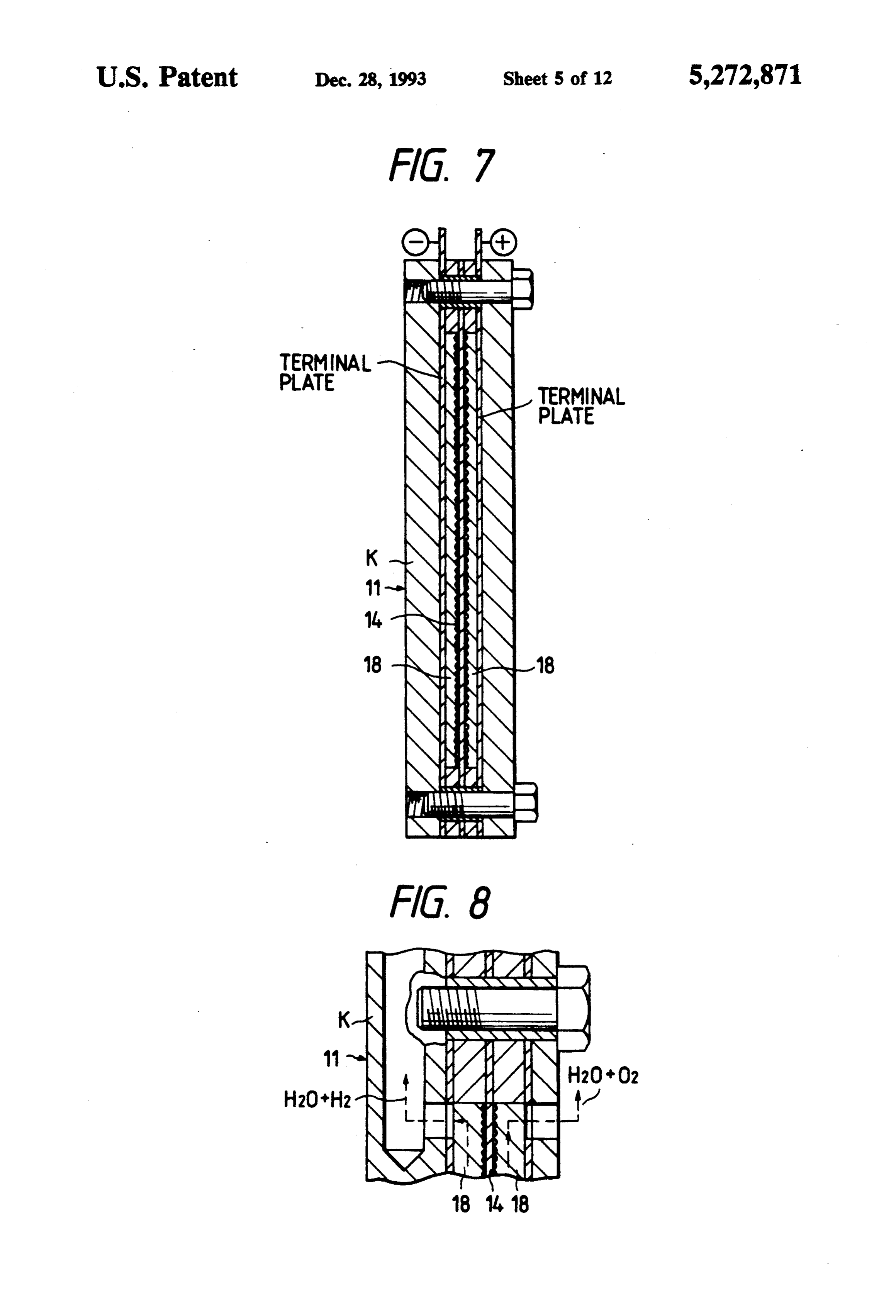
FIG. 7 is a longitudinal section of the H2 generator in In a preferred embodiment of the present invention, the apparatus shown in FIG. 6; the catalyzer may be packed with a NOx catalyst such FIG. 8 is a partial enlarged section of the essential as a zeolite-based catalyst. If desired, the electrolytic part of the H2 generator in the apparatus shown in FIG. O cell in the hydrogen generator may be supplied with 6; from a water tank or with water vapor that is contained FIG.9 is a block diagram showing the basic layout of in part of the exhaust or blow-by gases as introduced an apparatus according to the second embodiment of into the system, so that water electrolysis is effected to the present invention; generate H2.
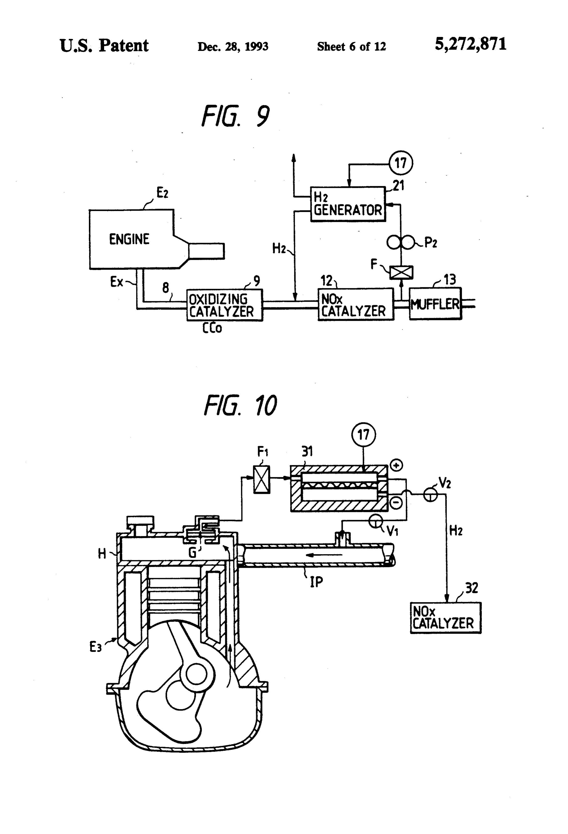
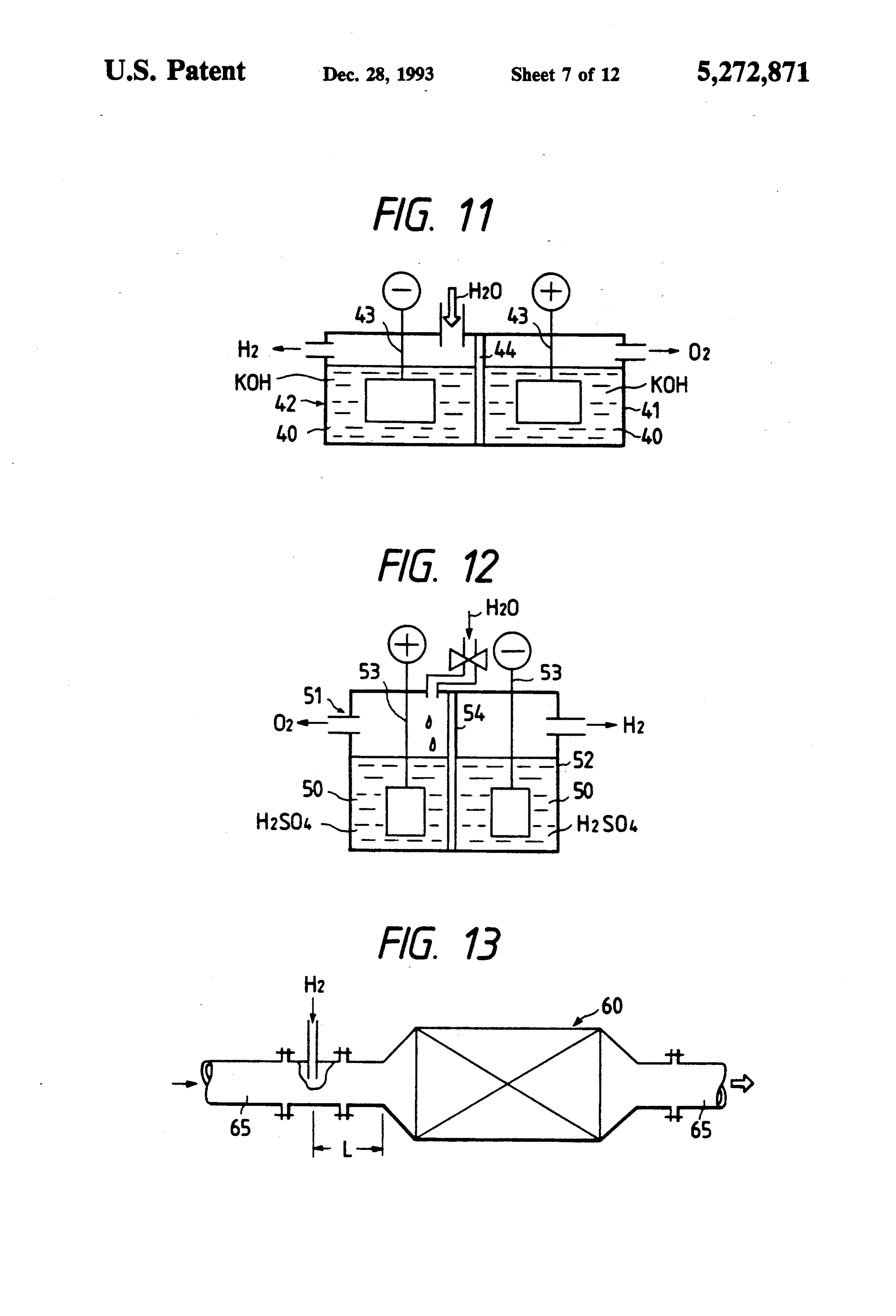
FIG. 10 is a diagram showing the basic layout of an 15 In addition to the solid electrolyte having a proton or apparatus according to the third embodiment of the hydroxyl ion conducting capability, various other elec present invention; trolytes may be used to effect water electrolysis in the FIG. 11 is a diagram showing the basic layout of the hydrogen generator and they include aqueous solutions H2 generator in an apparatus according to the fifth of alkalies such as NaOH and KOH, as well as aqueous embodiment of the present invention; solutions of acids such as H2SO4. Thus, one embodiment of the method of the present
FIG. 12 is a diagram showing the basic layout of the invention
H2 generator in an apparatus according to the sixth combustionforengine reducing nitrogen oxide from an internal is characterized in that hydrogen gas embodiment of the present invention;
FIG. 13 is a diagram showing the basic layout of the 25 a catalyzer provided in anis exhaust from a hydrogen generator supplied at the entrance to
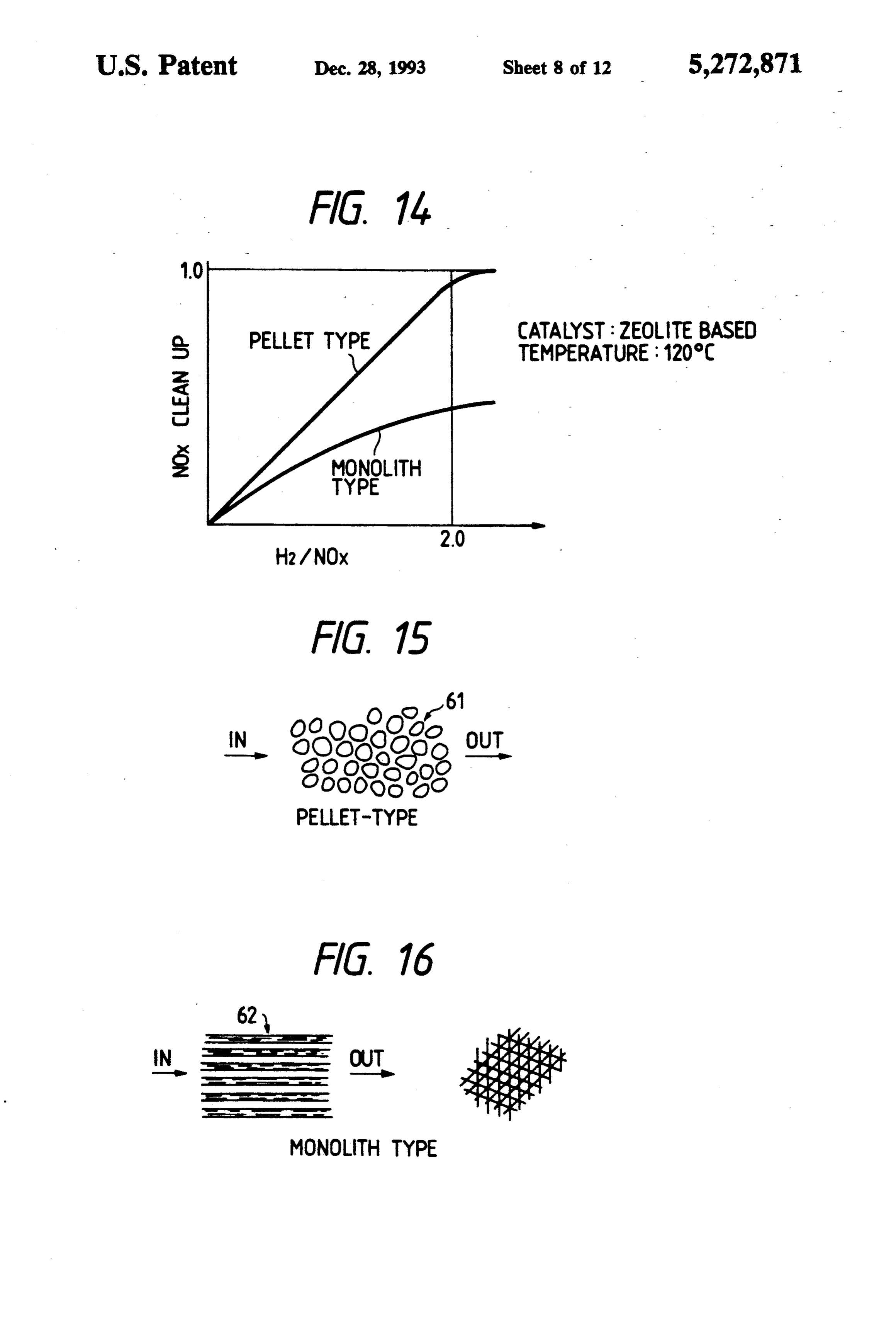
NOx converter in an apparatus according to the seventh nitrogen oxide in the exhaust emitted line by and that the the burning of embodiment of the present invention; a fuel feed in the combustion chamber are directly re FIG. 14 is a graph showing the Nox cleanup perfor duced and cleaned up with said hydrogen gas in a cold mance of the converter shown in FIG. 13; -
FIG. 15 is a diagram showing the structure of a pel 30 atmosphere not hotter than 350 C., thereby reducing let-type catalyst to be used in the converter shown in lytic reaction oxides, said nitrogen between said catalyzer performing a cata hydrogen gas and nitrogen ox
FIG. 16 is a diagram showing the structure of a so as to achieve decomposition oxides ides in the presence of nitrogen and oxygen gas into nitrogen gas and monolith-type catalyst to be used in the converter water, and said hydrogen generator creating hydrogen shown in FIG. 13; 35 gas by water electrolysis using an aqueous alkali or acid FIG. 17 is a longitudinal section showing the basic solution.
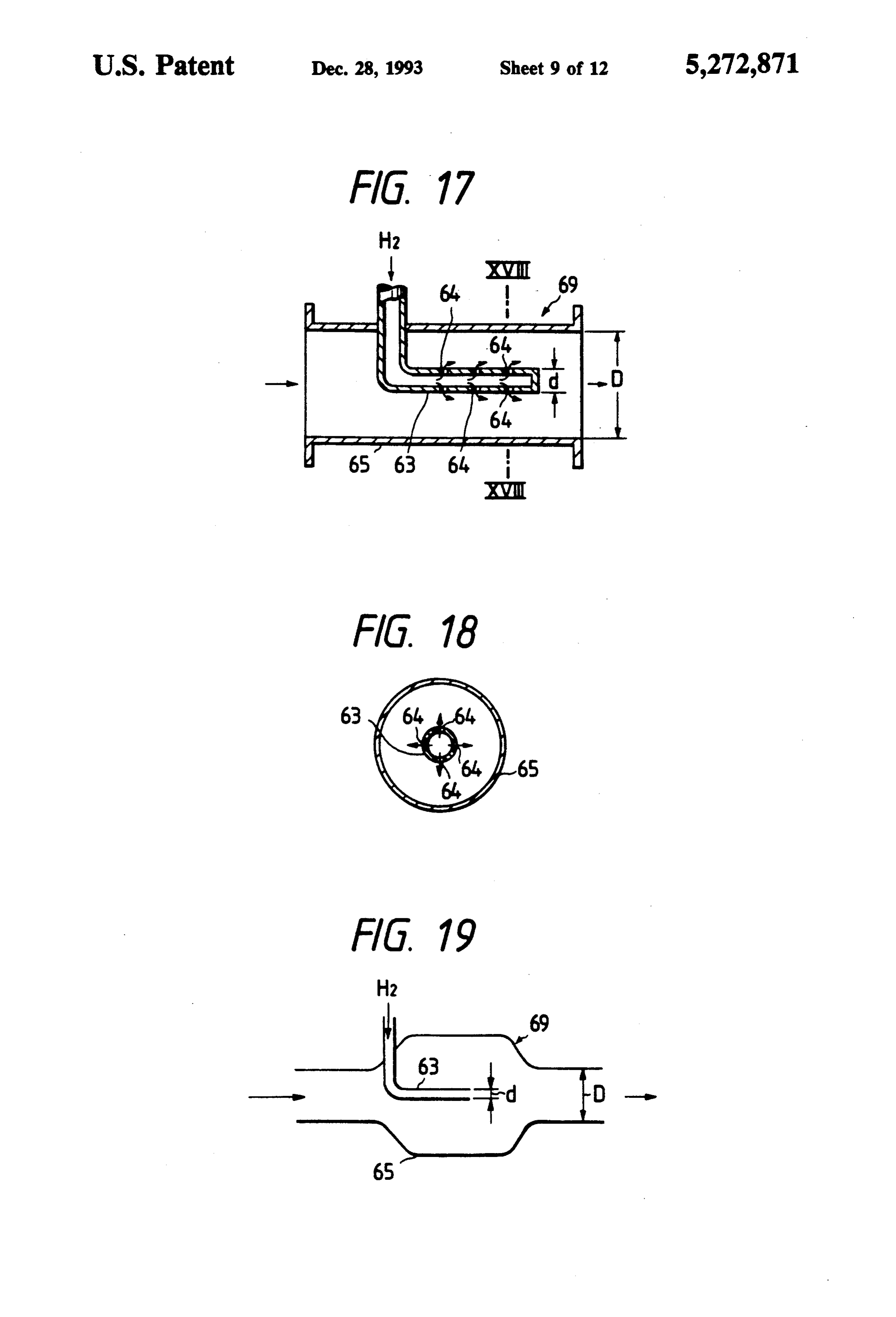
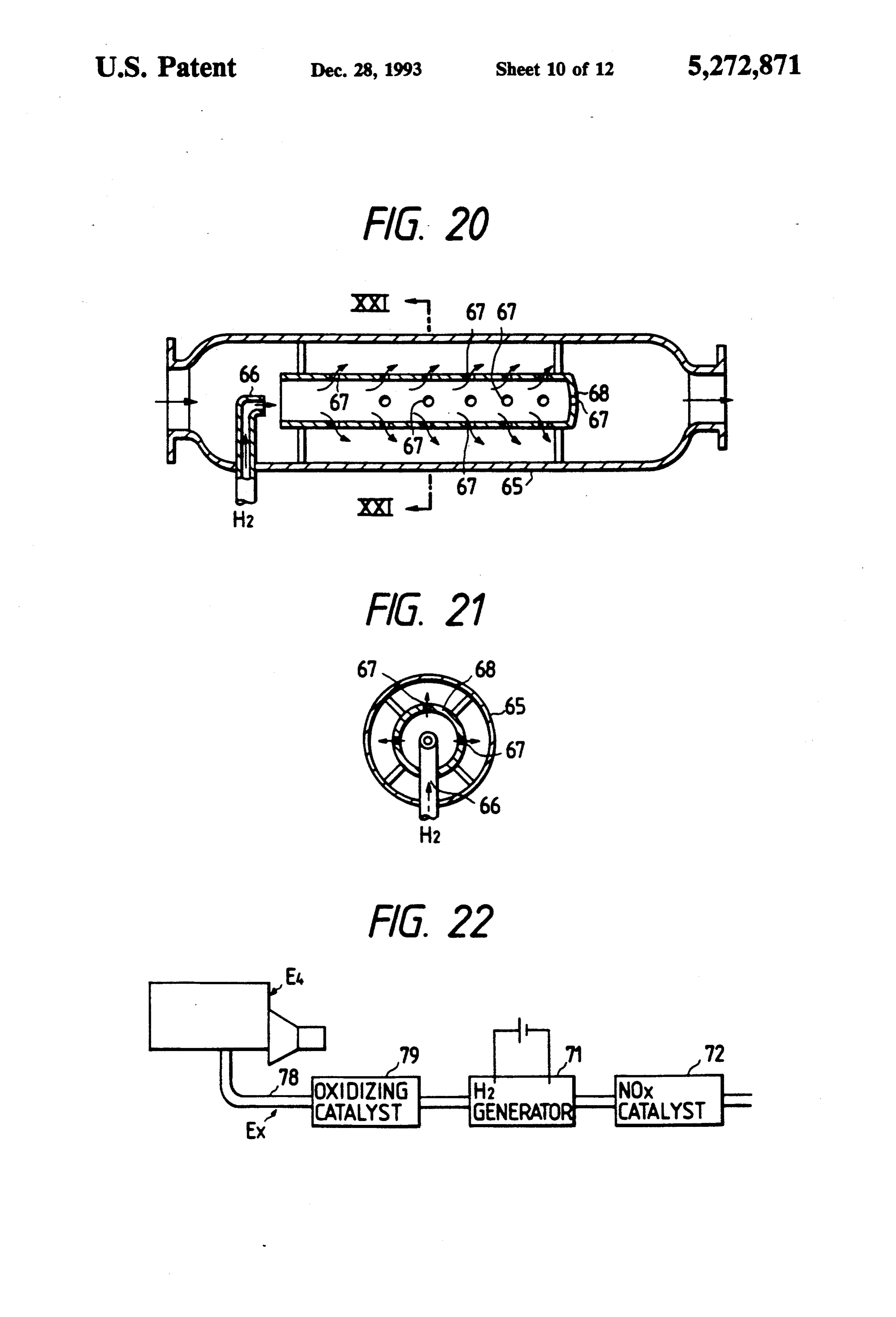
layout of the mixer in an apparatus according to the One embodiment of the apparatus of the present in seventh embodiment of the present invention; vention for reducing nitrogen oxides from an internal FIG. 18 is a cross section taken on line XVIII-X- combustion engine is characterized by comprising a VIII of FIG. 17; catalyzer provided in an exhaust line and a hydrogen FIG. 19 is a diagram showing the basic layout of a generator provided to communicate with the entrance modification of the mixer in an apparatus according to to said catalyzer so that it can be supplied with hydro the seventh embodiment of the present invention; gen gas, said catalyzer performing a catalytic reaction FIG. 20 is a longitudinal section showing another between hydrogen gas and nitrogen oxides so that they modification of the mixer in an apparatus according to 45 are decomposed into nitrogen gas and water in the the seventh embodiment of the present invention; presence of nitrogen oxides and oxygen gas in the ex FIG. 21 is a cross section taken on line XXI-XXI of haust emitted by the burning of a fuel in the combustion FIG. 20; chamber of the internal-combustion engine as it is sup FIG. 22 is a block diagram showing the basic layout plied from a fuel feeder, said hydrogen generator creat of an apparatus according to the eighth embodiment of 50 ing hydrogen gas by water electrolysis using an aqueous the present invention; alkali or acid solution, the nitrogen oxides in said ex FIG. 23 is a graph showing the NOx cleanup perfor haust being directly reduced and cleaned up with the mance of the apparatus shown in FIG.22; hydrogen gas from said hydrogen generator in a cold FIG. 24 is a longitudinal section showing the basic atmosphere not hotter than 350 C., thereby reducing layout of an integral combination of an exhaust muffler 55 said nitrogen oxides.
and a catalytic converter in an apparatus according to In another preferred embodiment of the present in the ninth embodiment of the present invention; vention, a NOx sensor and an air intake sensor may be FIG. 25 is a cross section taken on line XXV-XXV provided on the exhaust pipe in the exhaust line and the of FIG. 24; flow rate of NOx is computed from the outputs of the FIG. 26 is a longitudinal section showing the basic two sensors, so that an appropriate H2 level is deter layout of another integral combination of an exhaust mined at all times to control the voltage or current to be muffler and a catalytic converter in an apparatus ac supplied to the electrolytic cell in the hydrogen genera cording to the ninth embodiment of the present inven to.
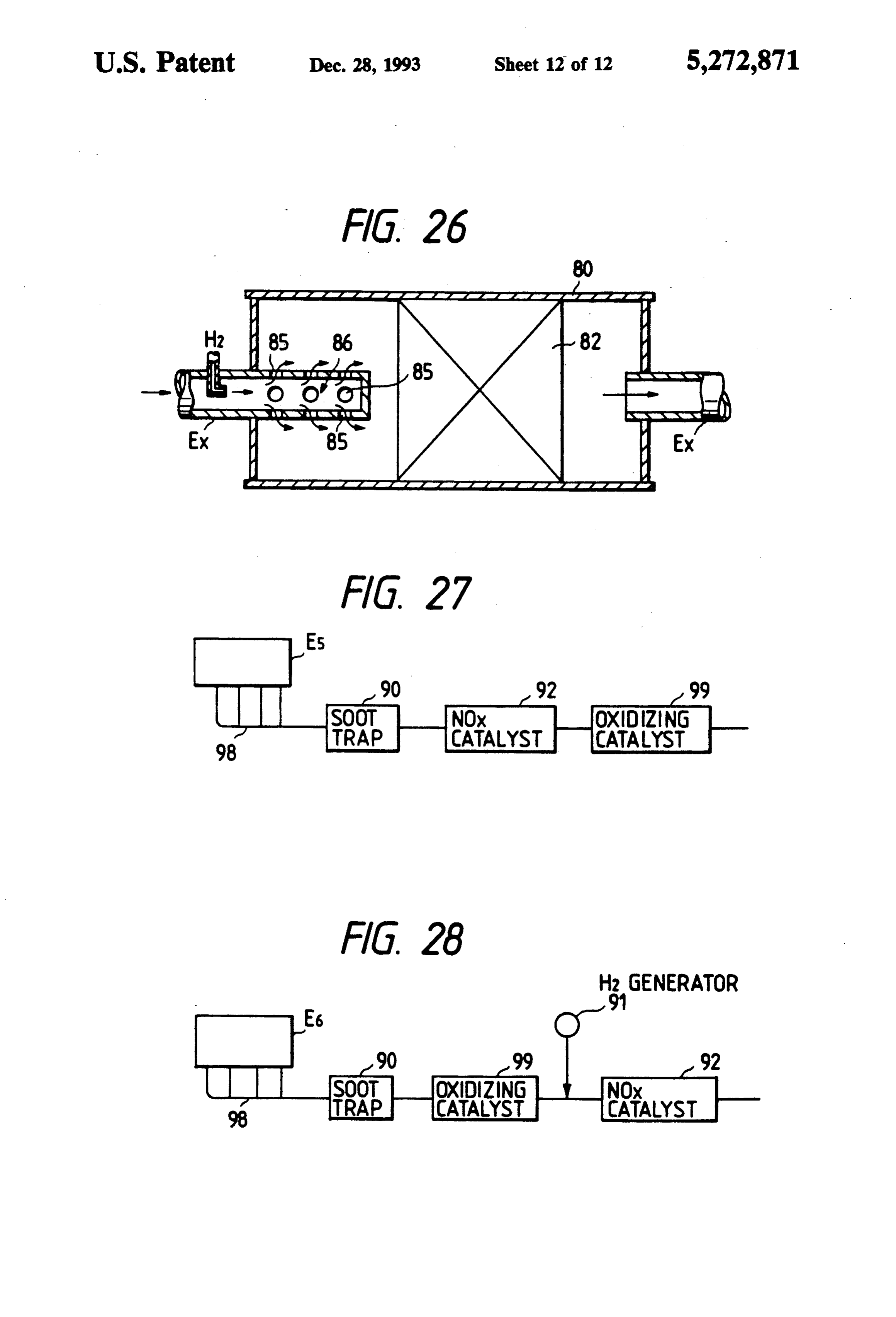
tion; In yet another preferred embodiment, sensors may be FIG. 27 is a block diagram showing the basic layout 65 provided that are capable of detecting various condi of a prior art version over which the apparatus accord tions of operation in the internal-combustion engine ing to the tenth embodiment of the present invention is such as its rotational speed, the negative pressure on the an improvement; and intake pipe, the opening of the intake control valve and
Page 16
S 6 the amount of fuel injection from an injection pump as containing exhaust is also called a "lean NOx catalyst", a fuel feeder and the flow rate of NOx is predictively which is selected from among those catalysts which computed from the outputs of those sensors to control support noble metals such as Pt. The relationship be the voltage or current to be supplied to the electrolytic tween temperature and the NOx cleanup by the lean cell in the hydrogen generator (this approach may be NOx catalyst is as shown in FIG. 4B. If CO or active referred to as a "learning control" system). HC is present in gases that flow into the catalyzer, those In another preferred embodiment of the present in gases will cover the surface of the catalyst through vention, a mixer may be provided or the muffler in the adsorption, thereby blocking the reaction of NOx re exhaust line may be effectively used in order to achieve duction with H2.
uniform mixing of H2 and the exhaust at the entrance to 10 Conventionally, the catalyzer is installed near the the catalyzer. exhaust manifold on the engine, so the catalyst is ex The method and apparatus of the present invention posed to the exhaust which is as hot as 800-900' C. at for reducing nitrogen oxides from internal combustion maximum. In addition, the exhaust from the lean burnt engines have been invented to solve the aforementioned engine which uses an air-fuel mixture leaner than the problems of the prior art and the basic layout of the 15 stoichiometric ratio is substantially free from H2. Under system is shown in FIG.1. The main thrust of the pres the circumstances, it has been impossible in the prior art ent invention is to perform NOx reduction with H2 on to utilize the characteristics of the catalyst that is on the the lower temperature side in such a way that it is in lower temperature side.
cluded within the full operating range of the engine E. In contrast, the method and apparatus of the present The second characteristic point of the invention is to 20 invention which are composed in the manner shown in install the H2 generator 1 in the system in order to en FIG. 1 have the advantage that whether the engine is able operation on the lower temperature side. The third operated at an air/fuel ratio richer or leaner than the point that characterizes the invention is to control the stoichiometric value or at the stoichiometric ratio (i.e., H2 generator 1 in accordance with the operating state of irrespective of the presence or absence of O2 from the the engine E or NOx in the exhaust so that H2 can al 25 exhaust or of the concentration of O2 in the exhaust), ways be supplied in an amount corresponding to NOx in NOx can be reduced with the catalyst so that the best the exhaust (this contributes to reduction in the electric performance of the engine (automobile) and fuel can be power for generating H2). selected without considering the conditions for reduc If a catalyzer 2 is exposed to an excessively high ing the NOx content.
temperature, H2 will react with O2, whereby the selec FIG. 5 is a graph showing the relationship between tivity for the reaction between H2 and NOx is lost. the relative supply of H2 and the relative cleanup of Hence, the catalyzer 2 must be located near the muffler NOx; the horizontal axis plots the supply of H2 relative 3 in order to avoid exposure to temperatures higher to NOx and the vertical axis plots the relative reduction than 350 C. In the system shown in FIG. 1, a water (cleanup) of NOx. As FIG. 5 shows, if H2 is supplied in tank 4 is provided and the water it supplies is electro 35 two moles per mole of NOx, all NOx will theoretically lyzed to generate H2. The generated H2 is supplied at a be reduced and cleaned up on the condition that it is point near the entrance to the catalyzer 2. By-product completely mixed with H2. In fact, however, NOx and O2 is either released into the atmosphere or mixed with O2 will not completely mix and the relative reduction of air taken into the system. To insure that H2 is supplied in NOx is as plotted by the curve for the experimental. an amount corresponding to the NOx in the exhaust, the The curve for the experimental is partly better than that system adopts the following method: the air taken in by for the theoretical and this is due to the fact that the the engine E is measured with a sensor 5 and the con water vapor in the exhaust is converted to H2 by de centration of NOx in the exhaust is measured with a composition on the noble metal based catalyst. Hence, NOx sensor 6; a control power supply 7 is turned on to more H2 than supplied will react with NOx. compute the flow rate of NOx from the outputs of the 45 In another embodiment of the present invention, a two sensors 5 and 6; then the current to be supplied to mixer for mixing H2 with the exhaust may be provided the electrolytic cell in the H2 generator is controlled so at the entrance to the catalytic converter in the appara that H2 is generated in an amount that corresponds to tus for NOx by reduction and cleanup with H2. In order the flow rate of NOx. to maintain an advantageous range of the operating The advantages that are achieved by the method and temperature, the hydrogen generator which is a compo apparatus of the present invention for reducing nitrogen nent of the apparatus for cleaning up nitrogen oxides oxides from internal combustion engines are specifically may be provided at a stage in the exhaust line of the described below. internal-combustion engine that is subsequent to the The lean burnt engine and the diesel engine are basi oxidation catalyst provided at the exit of the exhaust cally the same in that the exhaust contains excess O2 and 55 manifold. For the same purpose, the catalyzer may be the concentration of O2 in the exhaust increases as the provided either within or downstream of the muffler air/fuel ratio increases. The catalyst for reducing and where the exhaust expands to have its temperature de cleaning up the NOx in such O2 containing exhaust is creased below 200 C.
called a "lean catalyst', which is often selected from In yet another embodiment, water or water vapor to among noble metal based catalysts such as those sup 60 be supplied to the hydrogen generator may be replaced ported on zeolite. The relationship between tempera by aqueous methanol or the vapor of a mixture of meth ture and the NOx cleanup by the lean catalyst is as anol and water and this helps achieve a marked drop in shown in FIG. 4A. The reaction between HC and NOx the electric power required for H2 generation. occurs mainly in the high-temperature (>350' C.) In another embodiment of the present invention that range. On the other hand, in the low-temperature (<25 relates to a method of reducing NOx by supplying H2 0-350' C.) range, a reaction for reducing NOx with H2 from the hydrogen generator and reducing and cleaning occurs, enabling the cleanup of NOx. Another type of up the NOx in the engine exhaust in the presence of O2, catalyst for reducing and cleaning up the NOx in the O2 a means of oxidizing HC and CO such as oxidation
Page 17
catalyst, a three-way catalyst or an exhaust reactor may Various embodiments of the present invention are be provided near the exhaust manifold on the engine described below with specific reference to the accom and, at the same time, a Pt-on-zeolite catalyst may be panying drawings.
used in the catalytic converter for NOx cleanup. If First Embodiment desired, the NOx catalytic converter may be provided 5 with a sound dampening effect so that it can be made The first embodiment of the present invention is integral with the exhaust muffler. shown in FIG. 6 and it relates to the case where the In yet another embodiment of the apparatus for system of the invention is applied to a lean burnt engine cleaning NOx by reducing it with H2, adaptation for use having a displacement of 1 L. The components that are with a diesel engine may be effected by providing a soot 10 the same as those shown in FIG. 1 are identified by like trap and a means of oxidizing the products of incom numerals. The engine E1 used in the first embodiment plete combustion upstream of the NOx catalytic con will operate at an air/fuel (AMF) ratio of 14-14.5 verter. The method and apparatus of the present inven tion for reducing nitrogen oxides is not solely applicable (slightly richer than the stoichiometric ratio or at the stoichiometric ratio) during idling, at A/F of 13-14 (on to gasoline engines and diesel engines; they are also 15 the fuel-rich side) with full load at each rotational speed effectively applicable to hydrogen engines and Stirling and during rapid acceleration, and at A/F of 18-23 (on engines although the last-mentioned are external-com the lean side) under other operating bustion engines. If the present invention is to be applied the concentration of O2 in the exhaustconditions. will vary
Hence, from 0 to a hydrogen engine, there is no need to provide a to about 10%. The exhaust system Ex is composed hydrogen generator and hydrogen as a fuel may simply 20 such a way that an oxidation catalyst 9 is provided in at be supplied through a bypass in the form of a controller. the exit of an exhaust manifold 8 to oxidize and clean up The present invention is also applicable to the Stirling HC, CO and other products of incomplete combustion. engine with as great effects as are achieved with inter Further, a reduction catalyst 12 is provided down
stream
In a further embodiment of the present invention, 25 provided of a muffler 13 as a sound damper. A mixer 10 is there are provided a method and an apparatus for re order to achieve at the entrance of the reduction catalyst 12 in ducing nitrogen oxides from an internal combustion The reduction catalyst uniform mixing of H2 with the exhaust. engine, in which a Pt composed catalyzer for perform 2 g/l on a 1.3 l monolith 12 has Pt carried in an amount of ing a catalytic reaction between hydrogen gas and ni support coated with zeolite. trogen oxides so that they are decomposed into nitrogen 30 torAs11shown specifically in FIGS. 7 and 8, a H2 genera generates hydrogen gas by water hydrolysis with gas and water in the presence of nitrogen oxides and oxygen gas in the exhaust emitted by the burning of a proton conductive membranes (Nafion membranes). fuel feed in the combustion chamber of the engine is The H2 generator 11 has such a structure that a cell case provided in the exhaust system while, at the same time, K contains a proton conductive membrane (solid elec a hydrogen generator for creating hydrogen gas is pro 35 trolyte) 14, with an anode being provided on one side of the membrane and a cathode on the other side. A cur vided to communicate with the entrance of the cata lyzer so that it can be supplied with hydrogen gas, in rent collector 18 is provided to have a dc current flow which method and apparatus the nitrogen oxides in the between the anode and the cathodes so that water or exhaust are directly reduced and cleaned up with the water vapor is electrolyzed on the anode surface to hydrogen gas from the hydrogen generator in a cold evolve oxygen gas and protons. The evolved protons atmosphere not hotter than 350° C., thereby reducing will move through the conductive membrane 14 to said nitrogen oxides. The catalyst in the catalyzer is a reach the cathode, whereupon hydrogen gas is gener Pt-based NOx catalyst such as one that has Pt carried on ated on the cathode surface. The anode is preferably a porous support such as alumina, silica or zeolite. The made of platinum (Pt), iridium (Ir) or some other metal catalyst may be of a pellet or monolith type and it may 45 that has low O2 overvoltage whereas the cathode is contain an alkaline earth element or a rare earth element preferably made of platinum, palladium (Pd) or some as a cocatalyst for Pt. other metal that has low hydrogen overvoltage. The It is already known that NOx can be reduced with conductive membrane 14 having the structure de H2 on a Pt catalyst under an oxygen-free condition. See, scribed above and which is depicted in FIGS. 7 and 8 is for example, T. P. Kobylinski and B. W. Taylor, Jour supplied with 2-2.5 volts per sheet and six sheets are nal of Catalysis, 33,376 (1974), as well as K. Otto and H. connected in series to be supplied with 12-15 volts. In C. Yao, Journal of Catalysis, 56, 21 (1979) and 66,229 the first embodiment under discussion, H2 is required in (1980), which describe the results of experiments con an amount twice that of NOx, so depending on the ducted on a NO/H2/Ar system in a totally reducing concentration on of NOx in the exhaust from the engine atmosphere and at the stoichiometric air/fuel ratio. J. 55 E1, the power consumption is ca. 60-70 watts at vehicle H. Jones, J. T. Kummer, K. Otto, M. Shellef and E. E. speed of 50 km/h and ca. 300 watts at maximum output Wever, Environmental Science & Technology, 5, 790 and horsepower. The effect the power consumption (1971) describes successful cleanup of NO in the pres causes on the gas mileage under various operating con ence of hydrogen added to the exhaust from an actual ditions is no more than 1-2%, which is negligible com engine. However, the experiment was conducted at an pared to 15-20% of the merit of fuel cost reduction as air/fuel ratio near the stoichiometric value with the achieved by use of a lean burnt engine. Thus, the good oxygen concentration being varied up to 1.5%. The fuel economy of the lean burnt engine will not be im reference also shows that not only Pt but also Pd had paired by the application of the present invention. catalytic activity. For H2 generation, about 12 g is necessary per hour if As a result of intensive studies, the present inventors the car is running at a speed of 50 km/h. Assuming that found that among various noble metals, only Pt was the vehicle will run about 15,000 km a year, a water effective in promoting the reaction between NOx and tank 4 having a capacity of 3-41 will suffice for practi H2 in the presence of excess oxygen. cal purposes.
Page 18
Oxygen is produced simultaneously with the evolu for bringing about comparable results to the aforemen tion of H2 and it is supplied to the oxidation catalyst 9, tioned first embodiment of the invention. thereby improving the efficiency of CO cleanup. The aqueous methanol desirably has a methanol con As described above, the system in accordance with centration of 10 to 80%. Below 10%, the intended re the first embodiment of the present invention has the duction in power consumption cannot be achieved. tank 4 containing a small amount of water, electrolyses Beyond 80%, the voltage for electrolysis will become water by means of the proton conductive membrane 14 instable. Substituting aqueous methanol for water or in the H2 generator 11 and reduces NOx with H2 making water vapor is also possible in each of the H2 generators use of the characteristic of the NOx reduction catalyst that use a hydroxyl ion conductive membrane or an 12 on the low-temperature side. Hence, the present 10 aqueous solution of sulfuric acid.
invention provides a practically advantageous system Second Embodiment for reducing the lean burnt NOx that is capable of effi cient NOx reduction irrespective of the operating A/F The basic layout of the system according to the sec ratio of the engine E1. - ond embodiment of the present invention is shown in The foregoing description assumes cleanup of NOx FIG. 9; those components which are the same as what by direct reduction with H2 that is evolved by electroly are used in the first embodiment are identified by like numerals and will not be described in detail. The major sis of water with the proton conductive membranes 14. difference
It should, however, be noted that the method of evolv from the first embodiment is that the H2 ing H2 is in no way limited to the one adopted in the first 20 generator 21 is not supplied with water but supplied embodiment; if desired part of the engine exhaust or the with part of the exhaust from the engine E2, which is gas of ventilation in the engine crankcase may be intro aspirated by a pump P2 to be introduced into the H2 duced into the H2 generator 11 having the proton con brane or a21polymer generator (composed of a proton conductive mem ductive membrane 14 so that the water vapor in the filter F for generatingelectrolyte membrane) through a gases is decomposed to evolve H2. In the absence of the 25 vided into compartments by aH2polymer H2. The generator 21 is di need to provide a water tank, this modified version membrane having electrodes and the exhaust electrolyte offers the practical advantage of being suitable for use at the entrance to the anode side. The wateris vapor supplied
with comparatively large cars or diesel engines. the exhaust is absorbed by the proton conductive mem In another modification of the first embodiment of the present invention, water or water vapor to be sup 30 brane cathode 14, where it is electrolyzed to evolve H2 on the side. The evolved H2 is supplied at the entrance plied to the hydrogen generator may be replaced with to the NOx catalyzer 12, whereby NOx in the exhaustis aqueous methanol or the vapor of a mixture of methanol reduced and cleaned up. The NOx catalyst has Pt car and water and this helps achieve a marked reduction in ried in an amount of 2 g/l on a 1.3 l monolith support the electric power required for H2 generation. The coated with alumina. The exhaust supplied to the anode modification to be described below is the same as de 35 side will lose water vapor but contains O2 generated by scribed in the preceding paragraphs except that water electrolysis when it is discharged to the ambient atmo or water vapor to be supplied to the hydrogen genera sphere. The power to be supplied to the proton conduc tor is replaced by aqueous methanol; namely, the water tive membrane 14 may be controlled in the same man tank shown in FIG. 6 is charged with aqueous methanol ner as in the first embodiment, bringing about compara consisting of 50% methanol and 50% water and the tive results.
aqueous methanol is electrolyzed in the hydrogen gen erator. The cathodic reaction that occurs in this case is Third Embodiment the same as what occurs in the electrolysis of water (the As shown in FIG. 10, the third embodiment differs reaction for H2 generation by reduction of H); on the from the first and second embodiments in that the water other hand, the reaction at the anode is that for generat 45 vapor containing gas to be supplied to the electrolytic ing CO2 gas by the oxidative reaction of aqueous metha cell 31 is replaced by a blow-by gas G that occurs in the nol. engine E3. The blow-by gas G obtained from the cylin By changing the anodic reaction in water electrolysis der head H of the engine E3 by removing the oil mist is from the conventional reaction for oxygen generation further freed of foreign matter and oil mist by means of to the oxidative reaction of aqueous methanol, the volt the filter F before it is introduced into the electrolytic age for electrolysis can be reduced by about 50% from cell 31. As is ordinary ventilation, the gas emitted from ca. 2 volts to ca. 1 volt. In other words, the power the electrolytic cell 31 is returned to the intake pipe IP consumption can be reduced by 50% compared to the so that it is admitted into the engine E3 together with air case of water electrolysis. This is because the oxidation intake. A regulating valve V is provided halfway be potential for aqueous methanol is closer to the potential 55 tween the electrolytic cell 31 and the intake pipe IP so for H2 generation than to the potential for O2 genera that the pressure in the cell will in no case be negative. tion. Hydrogen gas is evolved on the cathode side and it is As described above, the system according to the supplied to the NOx catalyst 32 after pressure adjust modified version of the first embodiment of the present ment to a predetermined level by means of a regulating invention has the tank 4 containing aqueous methanol, valve V2. The third embodiment will achieve compara electrolyses the aqueous methanol by means of the pro ble results to the first and second embodiments. ton conductive membrane 14 in the H2 generator to Fourth Embodiment evolve H2 and reduces catalyst 12 on the low-tempera ture side. Hence, the system is a practically advanta The fourth embodiment is essentially the same as the geous system for reducing the lean burnt NOx that is 65 foregoing embodiments except that the H2 generator 11 capable of not only efficient NOx reduction irrespective shown in FIGS. 7 and 8 uses a hydroxyl ion conductive of the operating A/F ratio of the engine E but also membrane 14 rather than the proton conductive mem achieving about 50% reduction in power consumption brane. The H2 generator 11 has such a structure that a
Page 19
cell case K contains the hydroxyl ion conductive mem trolyses water using an aqueous solution of H2SO450. brane (solid electrolyte) 14, with an anode being pro The H2 generator 51 has such a structure that a cell case vided on one side of the membrane and a cathode on the 52 is divided into two compartments by an ion conduc other side. A current collector 18 is provided to have a tive membrane 54, with an anode being provided in one dc current flow between the anode and the cathode so compartment and a cathode in the other compartment. that water or water vapor is electrolyzed on the cath A current collector 53 is provided to have a dc current ode surface to evolve hydrogen gas and hydroxyl ions. flow between the anode and the cathode, so that water The generated hydroxyl ions will move through the is electrolyzed on the anode surface to generate oxygen conductive membrane 14 to reach the anode, where gas and protons. The generated protons move through upon oxygen gas is generated on the anode surface. O the membrane 54 to reach the cathode, whereupon As described above, the system in accordance with hydrogen gas is evolved on the cathode surface. The the fourth embodiment of the present invention has the anode is preferably made of platinum (Pt), iridium (Ir) tank 4 containing a small amount of water, electrolyses or some other metal that has low O2 overvoltage water by means of the OH ion conductive membrane 14 whereas the cathode is preferably made of platinum, in the H2 generator 11 to produce H2, and reduces NOx 15 palladium (Pd) or some other metal that has low hydro with H2 making use of the characteristic of the NOx gen overvoltage. The H2 generator 51 having the struc reduction catalyst on the low-temperature side. Hence, ture described above and which is depicted in FIG. 12 the system is a practically advantageous system for is supplied with a voltage of 2 to 2.5 volts per cell be reducing the lean burnt NOx that is capable of efficient tween anode and cathode, with six cells being con NOx reduction irrespective of the operating A/F ratio 20 nected in series to be supplied with 12 to 15 volts. of the engine Ei, bringing about comparable results to As described above, the system in accordance with those achieved by the foregoing embodiments. The the sixth embodiment of the present invention has a tank NOx catalyst has Pt carried in an amount of 2 g/1 on a (not shown) containing a small amount of water, elec 1.3 l monolith support coated with silica. trolyses water in the aqueous solution of sulfuric acid in 25 the H2 generator 51 to produce H2, and reduces NOx
Fifth Embodiment with H2 making use of the characteristic of the NOx
FIG. 11 shows a H2 generator that is used in the reduction catalyst on the low-temperature side. Hence, system according to the fifth embodiment of the present the system is practically advantageous system for re invention. The H2 generator indicated by 41 electroly ducing the lean burnt NOx that is capable of efficient ses water using an aqueous solution of potassium hy 30 NOx reduction irrespective of the operating A/F ratio droxide 40. The H2 generator 41 has such a structure of the engine E1, bringing about comparable results to that a cell case 42 is divided into two compartments by those achieved by the foregoing embodiments. an ion conductive membrane 44, with an anode being Seventh Embodiment provided in one compartment and a cathode in the other compartment. A current collector 43 is provided 35 In the foregoing embodiments, it was found that the to have a dc current flow between the anode and the system for reducing NOx from engine exhaust by reduc cathode, so that water is electrolyzed on the cathode ing and cleaning up the NOx with the combination of surface to generate hydrogen gas and hydroxyl ions. either a zeolite based catalyst or a Pt/zeolite catalyst The generated hydroxyl ions move through the mem and an apparatus for generating H2 by electrolysis of brane 44 to reach the anode, whereupon oxygen gas is water with a proton conductor experienced substantial evolved on the anode surface. The anode is preferably differences in the performance of NOx reduction de made of platinum (Pt), nickel (Ni) or some other metal pending upon the conditions for H2 supply and on the that has low O2 overvoltage whereas the cathode is construction of the apparatus. FIG. 13 shows the sys preferably made of platinum, palladium (Pd), iron (Fe) ten according to the seventh embodiment of the pres or some other metal that has low hydrogen overvolt 45 ent invention, in which an engine exhaust containing age. The H2 generator 41 having the structure described NOx and O2 is allowed to flow through the catalyzer above and which is depicted in FIG. 11 is supplied with while H2 is supplied upstream of the catalytic converter. a voltage of 2 to 2.5 volts per cell between anode and The cleanup of NOx as accomplished in this embodi cathode, with six cell being connected in series to be ment is shown in FIG. 14. The horizontal axis of the supplied with 12 to 15 volts. SO graph shown in FIG. 14 plots the supply of H2 relative As described above, the system in accordance with to NOx, with 2.0 referring to the case where H2 is sup the fifth embodiment of the present invention has a tank plied in two moles per mole of NOx. The vertical axis of (not shown) containing a small amount of water, elec the graph plots the relative cleanup of NOx by reduc trolyses water in the aqueous solution of potassium tion, with 1.0 referring to complete cleanup of NOx. hydroxide 40 in the H2 generator 41 to produce H2, and 55 If the converter indicated by 60 in FIG. 13 is packed reduces NOx with H2 making use of the characteristic with a pellet-type catalyst as shown by 61 in FIG. 15, of the NOx reduction catalyst on the low-temperature high NOx cleanup is achieved as is clear from FIG. 14. side. Hence, the system is a practically advantageous If a monolith-type catalyst as indicated by 62 in FIG. 16 system for reducing the lean burnt NOx that is capable is used in place of the pellet type, the NOx cleanup of efficient NOx reduction irrespective of the operating deteriorates given the same supply of H2. In other A/F ratio of the engine, bringing about comparable words, more H2 must be allowed to flow to attain the results to those achieved by the foregoing embodi same NOx cleanup and, hence, more electric power is ments. necessary to generate H2, leading to more fuel con Sixth Embodiment sumption by the engine.
65 The pellet-type catalyst 61 shown in FIG. 15 has the
FIG. 12 shows a H2 generator that is used in the advantage that even if H2 does not mix well with the system according to the sixth embodiment of the pres exhaust gas to provide a concentration profile of H2 at ent invention. The H2 generator indicated by 51 elec the entrance to the catalyzer, the two gases will inter
Page 20
mix thoroughly as they pass through interstices be The sizes (diameters or cross-sectional areas) of the tween pellets that form tortuous pathways, thereby tube 68 and the outer tube have substantial effects on producing a uniform mixture of H2 and the exhaust gas. the mixing efficiency and if the tube 68 is too small, The monolith-type catalyst 62 has a honeycomb most of the exhaust will flow between the two tubes and structure consisting of many hexagonal holes. The indi its dynamic pressure cannot be fully utilized. With ref vidual holes are independent of one another in a direc erence to FIGS. 20 and 21, the ratio of D to d (D: the tion parallel to the gas flow, so if there is a concentra diameter of the outer tube; d: the diameter of the inner tion profile of H2 at the entrance to the catalyzer, the tube) is advantageously in the range of ca. 3 to 1.7, with gases will not readily mix together in adjacent channels the best result being attained at a value near 2. as they flow toward the exit end. According to the 10 having The seventh embodiment of the present invention results of an actual experiment, the thickness of the the construction described above accomplishes satisfactory exhaust pipe could not be increased significantly on monolith-type mixing of H2 with the exhaust and even a catalyst will achieve a comparable NOx account of space limits and the gas flow rate was so fast cleanup to a pellet-type as to create a high-concentration zone close to the cen catalyst. Compared for the ter of the catalyzer, thus resulting in substantial failure 15 same cleanup, the system of this embodiment can save to supply H2 to the peripheral portion of the monolith power on the supply of H2 by ca. 30 to 60% and, hence, less catalyst. Hence, the H2 availability of the monolith-type the adverse is needed for H2 generation, thereby reducing catalyst is lower than that of the pellet type. effects on the engine output and fuel econ From the viewpoint of its performance as a compo 20 ony. Consider, for example, the case where a 1.6 l lean nent of the engine exhaust system, the pellet-type cata lyst has the disadvantage that the pellets will readily burnt gasoline engine is operated at a conventional disintegrate into particles upon vibration friction and speed ofpoint, typical where the engine is running at a rotational 2000 rpm producing a torque of 40 Nm. In this that the cross-sectional area of the gas passage is so case, NOx is discharged in an amount of 0.22 l/min small as to cause a greater drag resistance and, hence, a higher exhaust pressure, leading to deterioration of the 25 (based flow on a change with NO2) in the exhaust and the rate of H2 that is necessary to clean up the dis performance of the engine itself. Therefore, a monolith charged NOx by reduction with H2 is 0.66 l/min. In type catalyst is desirably used in the engine exhaust order system but if this is the case, special care is necessary for power of 192 watts H2 to generate must in an amount of 0.66 l/min, a be supplied to a H2 generator
H2 supply. - using a polymer proton conductive membrane. Under the circumstances, the seventh embodiment If the mixing of H2 with the exhaust is promoted by uses an apparatus of simple construction that is capable the apparatus shown in FIGS. 20 and 21 where D/d=2, of mixing H2 uniformly with the exhaust gas in a mono H2 need only to be supplied in an amount of about 0.44 lith-type catalyst so as to achieve a higher NOx cleanup l/min which is twice that of NOx(i.e. twice that of NO2 than when the pellet-type catalyst is used. A mixing 35 by mole ratio) and the power consumption is lowered to apparatus generally indicated by 69 in FIG. 17 has a H2 128 watts, achieving 64 W saving. The relationship injecting nozzle 63 inserted whose basic structure is between the power consumption by an automobile car shown specifically in FIGS. 17 and 18. The nozzle 63 is rying a 1.61 engine and its fuel economy varies with the in a hollow cylindrical form and bent in an L-shape in a operating conditions but is generally held to be in the direction parallel to the exhaust flow and it has a plural range of 0.1 to 0.25% /A in terms of the effect on fuel ity of injection orifices 64 formed radially in the side economy per ampere of current. Since the power wall. The number of orifices 64 is advantageously four source is a battery capable of supplying a voltage of 12 to six per row and they are arranged in either one or volts, 64 watts is equivalent to 5.33 A. Assuming 0.2% more rows (in the case shown in FIG. 17, the orifices 64 /A, the system offers a practical advantage in that the are arranged in three rows). 45 fuel consumption can be reduced by 1.06%. The outside diameter, d, of the nozzle 63 must be at least 20% of the inside diameter, D, of the exhaust pipe Eighth Embodiment 65. The drag resistance of the exhaust pipe will increase FIG. 22 shows an apparatus for cleaning up nitrogen as the value of d increases. Hence, in place of increasing oxides in accordance with the eighth embodiment of the d, part of the exhaust pipe 65 is flared as shown in FIG. present invention. As shown, a hydrogen generator 71 19. The distance, L, from the nozzle 63 to the converter for electrolyzing water vapor in the exhaust to evolve 60 must be at least twice D but no further improvement the necessary amount of hydrogen gas is provided in is achievable even if L is greater than D by a factor 10 series to the exhaust line and, at the same time, a cata or more. Another configuration that can be assumed by lyzer 72 is provided for causing a catalytic reaction the mixing apparatus is shown in FIGS. 20 and 21. As 55 between the hydrogen gas and nitrogen oxides so that shown, the H2 agitating zone is composed of a substan they are decomposed into nitrogen gas and water. tially double-wall structure that consists basically of a The hydrogen generator 71 is of such a structure that small-diameter H2 injecting nozzle 66 and a large-diam it has an anode provided on one side of a proton con eter tube 68 with a bottom that is provided with a plu ductive solid electrolyte and a cathode on the other rality of injection orifices 67 in the side wall. Injected side, with a dc current being applied between the anode H2 will first mix with the exhaust that flows into the and the cathode so that water vapor is electrolyzed on nozzle 66 under the dynamic pressure of the exhaust the anode surface to produce oxygen gas and protons. and the mixed gas will flow through orifices 67 to go The protons move through the solid electrolyte to outside the tube 68, undergoing further mixing by the reach the cathode, whereupon they are used to generate exhaust flowing between the tube 68 and the outer tube. 65 hydrogen gas on the cathode surface. The anode is This mixing process through two stages insures that H2 preferably made of platinum (Pt), iridium (Ir) or some will mix with the exhaust in a complete and uniform other metal that has low oxygen overvoltage whereas way. the cathode is preferably made of platinum, palladium
Page 21
(Pd) or some other metal that has low hydrogen over Under the circumstances, the system according to the voltage. The proton conductive solid electrolyte is ninth embodiment of the present invention facilitates made of a sinter of an acceptor doped perovskite-type the installation of the converter by using a muffler that oxide such as strontium oxide ceria (SrCeO3), strontium can accommodate the NOx catalyst to realize a com oxide zirconium (SrZrO3) or calcium oxide zirconium. pact structure. Further, this system which accommo Preferred examples of the acceptor are oxides of such dates the catalyst in the muffler is yet capable of effec elements as yttrium (Y), neodymium (Nd) and ytter tive NOx cleanup by adopting certain temperature con bium (Yb). The solid electrolyte under consideration ditions.
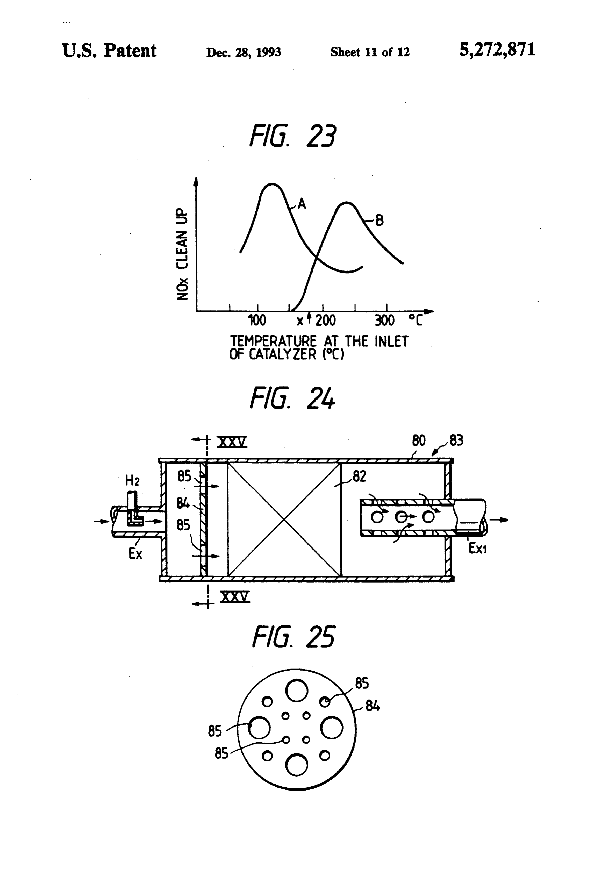
exhibits satisfactory proton conduction at 400' to 700' FIGS. 24 and 25 show the basic layout of the system C., so the hydrogen generator 71 in the system accord O according to the ninth embodiment of the present in ing to the eighth embodiment of the present invention is vention. As shown, a NOx catalyst 82 is accommodated desirably operated at 400' to 700' C. in an exhaust muffler 80 and this offers a great advan The catalyzer 72 uses either a Pt/zeolite or tage from the viewpoint of installation space since there Pt/alumina catalyst. The relationship between tempera is not need to connect a NOx converter and the exhaust ture and the NOx cleanup by these catalysts is as shown 5 muffler in series but only one of then need be provided. in FIG. 4B. In the low-temperature range not higher The exhaust muffler is typically located at the very than 200' C., the reaction between hydrogen and NOx end of the engine exhaust line and the temperature of occurs selectively, making it possible to accomplish the gas at the entrance to the muffler is inevitably low since it has been cooled before reaching the muffler.
very efficient cleanup of NOx through reduction with 20 The hydrogen. On the other hand, at 200 to 350° C. or inlet gas temperature is the highest when the engine higher, the reaction between HC and NOx occurs pre ismaximum running at a maximum rotational speed to produce a horsepower but even in that case, the temper dominantly, with HC contributing to the reduction of ature of interest is 150' to 200 C. and under normal NOx.
As described above, the hydrogen generator 71 and operating conditions that are often adopted, the temper the catalyzer 72 which are two major components of 25 ature is only about 100 to 150' C. Conventional three-way catalysts and Cu/zeolite the apparatus for cleaning up nitrogen oxides according catalysts to the eighth embodiment of the present invention have tion unlessarethenottemperature expected to achieve satisfactory reac
their own advantageous ranges of operating tempera ture. Therefore, the hydrogen generator 71 is prefera these catalysts cannot be accommodated in the muffler. In the foregoing embodiments, we have shown that bly provided at a stage subsequent to an oxidation cata NOx can be cleaned up at low temperatures if it is re lyst 79 that is located at the exit of an exhaust manifold duced with H2 but the temperature involved is about 78 in the exhaust line Ex of an internal-combustion 150 to 300' C., which is within a range somewhat engine E4 whereas the catalyzer 72 is preferably pro higher than the temperature at the entrance to the ex vided either within or downstream of a muffler (not 35 haust muffler.
shown) where the exhaust expands to have its tempera ture decrease below 200 C. Having this construction, in The present inventors conducted various experiments the system according to the eighth embodiment of the should betoselected order investigate as to which catalyst component for allowing the NOx reducing cata present invention will bring about almost comparable lyst to exhibit satisfactory activity when it is supplied results to those obtained in the foregoing embodiments. with H2 in the presence of O2. As a result, the inventors Ninth Embodiment found that Pd and Rh had no activity and that Cu had only low activity whereas Pt exhibited high activity.
In each of the embodiments described above, either a However, Pt has to be highly dispersed and, to this end, zeolite based catalyst or a Pt/zeolite catalyst is used and it must be carried on a support of high surface area (at hydrogen as generated in the hydrogen generator is 45 supplied at the entrance to the catalyzer so that NOx in least 100 m2/g), such as alumina, silica or zeolite. The present inventors made further studies on the the exhaust is reduced with H2. In this way, high NOx NOx reducing catalyst, as well as on the preliminary cleanup can be achieved even if the exhaust contains O2 treatment to be performed before mixing with H2. The at high concentration. results are shown in FIG. 23. When the engine exhaust However, compared to conventional NOx catalysts 50 was mixed with H2 and the mixture introduced to the such as three-way catalyst and a Cu/zeolite catalyst, the NOx reducing catalyst (Pt on alumina), the catalyst catalysts used in the foregoing embodiments are only activity was the highest at a temperature near 250' C., effective in reactions that take place at low tempera as indicated by curve B in FIG. 23. tures; the conventional catalysts use SV values (the When an after-burner, a reactor, a three-way catalyst, flow rate of a gas in cm/h per unit volume of catalyst 55 an oxidation catalyst, etc. were provided near the en in cm) in the range of 50,000 to 100,000 whereas the gine manifold to oxidize CO and HC in the exhaust so catalysts for the present invention require the use of that their contents would be reduced or eliminated smaller SV values (e.g., 10,000 to 60,000) in consider before being mixed with H2 and introduced into the ation of the reaction rate. If the system of the present NOx converter (catalyst), the temperature for catalyst's invention is to be installed on a vehicle, the temperature 60 activity shifted toward the lower side, with high activ of the gas at the entrance to the NOx converter is such ity being presented at 100' to 150' C., as indicated by that the converter must be positioned downstream of curve A in FIG. 23. This temperature coincided with the exhaust line, typically near the exhaust muffler. the gas temperature at the entrance to the exhaust muf However, certain types of vehicle have such a construc fler and could only be attained by incorporating the tion that only converters for high SV values (i.e., large Pt/zeolite catalyst 82 in the exhaust muffler 80. The converters) can be installed and, hence, the system of method of reducing NOx with the catalyst after remov the present invention is applicable to all types of vehi ing HC and CO achieves better cleanup and offers the cles. practical advantage of preventing the formation of soot
Page 22
on the catalyst due to the incomplete reaction between However, NOx cannot be cleaned up satisfactorily HC and O2. FIGS. 24 and 25 show a catalytic converter with HC unless the latter is supplied at a higher concen 83 that is provided with a sound dampening effect by tration than NOx. Further, depending on the catalyst to incorporating the monolith catalyst 82 (of Pt/zeolite be used in the NOx converter, the temperature of the system) in the exhaust muffler 80. gas at the exit of the NOx converter or the temperature The exhaust mixed with H2 is admitted at the en of the gas at the entrance of the oxidation catalytic trance to the catalytic converter 83 in the direction converter 99 will typically drop to a temperature in the indicated by an arrow, whereupon the exhaust impinges range of 300' to 200' C. or below and, hence, excess HC against a mixing plate 84. As it passes through a plural that has passed through the NOx converter 92 cannot ity various sized holes 85 in the plate 84, the exhaust 10 be efficiently oxidized to lower its content. Under the mixes thoroughly with H2 and the mixture flows into circumstances, the monolith catalyst 82. The mixing plate 84 has no crease but alsonot no only does the fuel consumption in marked improvement in the NOx holes in the center where the exhaust flow attains a maximum speed, so H2 will not be concentrated in the reduce the NOx content,because cleanup can be expected the the more one wants to more HC will be dis center of the monolith catalyst. The holes 85 are differ 15 charged.
ent in diameter, so the mixture of the exhaust flow with The system according to the tenth embodiment of the H2 will pass through those holes at different, not only causing the gases to be agitated but also producing a present invention features the ability to reduce nitrogen sound dampening effect by interference. In the system oxides without increasing the HC level of the exhaust shown in FIG. 24, an interference tube Ex1 is provided 20 from an engine such as a diesel engine that is to be after the monolith catalyst 82 to provide an even greater operated in a zone having high excess of air compared sound dampening effect. FIG. 26 shows a modified to fuel. A typical example of this system is shown in version of the system according to the ninth embodi FIG. 28. Water as possessed by a H2 generator 91 or the ment of the present invention and it brings about the water vapor in the exhaust from the engine E6 is di same result as is achieved by the system shown in FIGS. 25 rectly electrolyzed to yield hydrogen gas, which is 24 and 25; the only difference is that the mixing plate 84 supplied as a reducing agent into a NOx converter 92. is replaced by a mixing pipe 86 in a hollow tubular form. This enables the NOx in the exhaust to be reduced at Whichever configuration is adopted, the system accord low temperature. Hence, in accordance with the tenth ing to the ninth embodiment of the present invention embodiment, the exhaust from the engine E6 is first features an integral combination of the catalytic con supplied to the soot trap 90 where it is freed of diesel verter 83 and the exhaust muffler 80 and, hence, pres particulate; then, CO and HC are oxidatively removed ents a practical advantage in that it is compact enough from the exhaust by an oxidation catalyst or some other to provide great ease in installation on a vehicle. At the means of removing the products of incomplete combus same time, the system will insure high NOx cleanup tion; the remaining exhaust gas is mixed with H2 and over the full operating range of the engine. 35 supplied into the NOx converter 92, in which NOx is Tenth Embodiment cleaned up by reduction with H2. This procedure offers the practical advantage of achieving satisfactory reduc
Nitrogen oxides (NOx) produced in the cylinder of a tion in the content of HC since HC and other products diesel engine must be removed by a post-treatment such of incomplete combustion can be oxidized in a hot ex as a treatment with an exhaust catalyst. Compared to haust gas.
the gasoline engine, the diesel engine performs combus What is claimed is:
tion in the presence of greater excess of air. In the diesel 1. A method for reducing nitrogen oxides in exhaust engine, the excess of air relative to fuel (a measure for gases from an internal combustion engine, comprising the factor by which the stoichiometric ratio must be the steps of:
multiplied to perform combustion) typically ranges 45 supplying a hydrogen gas from a hydrogen generator from i.1 to 7 and even greater (for a gasoline engine for mixing into exhaust gases including nitrogen supplied with a premixed uniform air-fuel mixture, the oxides and oxygen gas at an upstream position of factor is 0.8 to 1.3). Hence, the exhaust from the diesel the catalyzer and in a muffler or a downstream engine contains O2 at high concentration whereas it position of said muffler, said muffler being posi contains smaller amounts of NOx reducing materials tioned close to said catalyzer, said catalyzer and such as CO, HO and H2, thereby presenting extreme muffler being provided in an exhaust line, said difficulty in catalytically reducing and cleaning up NOx hydrogen generator producing said hydrogen gas as a post-treatment of the exhaust.
A diesel engine exhaust line that is under intensive by electrolysis of water or water vapor and said review in various fields is shown in FIG. 27. The gas 55 catalyzer causing a catalytic reaction between the emitted from the diesel engine E5 is first fed to a trap 90 hydrogen gas and nitrogen oxides to decompose where "diesel particulate' such as soot are removed. into nitrogen gas and water vapor; and Then, NOx in the exhaust is reduced in a NOx catalyzer directly reducing said nitrogen oxides in said exhaust 92 and HC and other products of incomplete combus gases with said hydrogen gas under a low tempera tion are removed by oxidation in an oxidation catalyzer ture atmosphere of not higher than 350". 99. To enhance the reducing power of the NOx cata 2. An apparatus for reducing nitrogen oxides from lyzer 92, part of the fuel is injected into an exhaust exhaust gases including nitrogen oxides and an oxygen manifold 98 or the same is reinjected into the cylinder of gas from an internal combustion engine, said apparatus the engine at the end of the stroke of combustion, so comprising:
that the concentration of HC and other products of 65 a catalyzer for reducing said nitrogen oxides into a incomplete combustion in the exhaust will be made nitrogen gas and water vapor by a catalytic reac satisfactorily higher than that of NOx before the ex tion between a hydrogen gas and nitrogen oxides, haust is introduced into the NOx catalytic converter. said catalyzer being provided in an exhaust line;
Page 23
a muffler located upstream and close to said cata gen gas into said exhaust gas, in which said mixer con lyzer, said muffler being provided in said exhaust sists of a flared diameter portion of said exhaust pipe line; and and an injecting nozzle having a few orifices. a hydrogen generator for producing the hydrogen 15. An apparatus for reducing nitrogen oxides ac gas by the electrolysis of water or water vapor, cording to claim 14, wherein said injecting nozzle con thereby supplying said hydrogen gas into said ex sists of a small-diameter injecting nozzle and a large haust gases at an upstream position of said cata diameter tube with a bottom having a plurality of inject lyzer and in said muffler or a downstream position ing orifices in the side wall to be disposed downstream of said muffler; of said small-diameter injecting nozzle. whereby said nitrogen oxides are directly reduced 10 16. An apparatus for reducing nitrogen oxides ac with said hydrogen gas from said hydrogen genera cording to claim 2, wherein said catalyzer uses either tor under a low temperature atmosphere of not Pt/zeolite or Pt/alumina or Pt/silica catalyst. higher than 350 C. - 17. An apparatus for reducing nitrogen oxides ac 3. An apparatus for reducing nitrogen oxides accord cording to claim 2, further comprising a muffler for ing to claim 2, further comprising oxidizing means for 15 reducing noise of said combustion from said engine oxidizing HC, CO and other products of incomplete positioned near by an outlet for exhaust gas, wherein combustion, said oxidizing means being provided up said exhaust muffler is unified with said catalyzer. stream of said catalyzer. 18. An apparatus for reducing nitrogen oxides from 4. An apparatus for reducing nitrogen oxides accord exhaust gases including nitrogen oxides and an oxygen ing to claim 3, wherein oxygen gas emitted from said gas from an internal combustion engine, said apparatus hydrogen generator is transferred into at least one of the 20 comprising:
atmosphere, an intake-manifold of said engine and said a catalyzer for reducing said nitrogen oxides into a oxidizing means. nitrogen gas and water vapor by a catalytic reac 5. An apparatus for reducing nitrogen oxides accord tion between a hydrogen gas and nitrogen oxides, ing to claim 3, further comprising a soot trap upstream said catalyzer being provided in an exhaust line; of said oxidizing means for removing diesel particulate. and 6. An apparatus for reducing nitrogen oxides accord a hydrogen generator for producing the hydrogen ing to claim 3, wherein said oxidizing means is at least gas by the electrolysis of water or water vapor, one of an oxidation catalyst, a three-way catalyst and an thereby supplying said hydrogen gas into said ex exhaust reactor. haust gases at an upstream position of said cata 7. An apparatus for reducing nitrogen oxides accord 30 lyzer;
ing to claim 2, wherein said hydrogen generator is ap wherein;
plied to said water or water vapor by means of a water said nitrogen oxides are directly reduced with said tank. hydrogen gas from said hydrogen generator under 8. An apparatus for reducing nitrogen oxides accord a low temperature atmosphere of not higher than ing to claim 2, wherein said hydrogen generator is ap 350 C.; and plied to said water or water vapor from at least one of 35 said hydrogen generator is provided with a mixer for ventilation gas from a crankcase of said engine and a mixing uniformly said hydrogen gas into said ex part of said exhaust gas. haust gas, in which said mixer consists of a flared 9. An apparatus for reducing nitrogen oxides accord diameter portion of said exhaust pipe and an inject ing to claim 2, wherein said hydrogen generator uses a ing nozzle having a few orifices. solid electrolyte having a proton or hydroxyl ion con 40 19. An apparatus for reducing nitrogen oxides ac ducting capability for supplying said water or water cording to claim 18, wherein said injecting nozzle con vapor. sists of a small-diameter injecting nozzle and a large 10. An apparatus for reducing nitrogen oxides ac diameter tube with a bottom having a plurality of inject cording to claim 2, wherein said hydrogen generator ing orifices in the side wall to be disposed downstream uses an aqueous solution of one of alkali hydroxide and 45 of said small-diameter injecting nozzle. sulfuric acid and an ion conductive membrane for sup 20. An apparatus for reducing nitrogen oxides from plying said water or water vapor. exhaust gases including nitrogen oxides and an oxygen 11. An apparatus for reducing nitrogen oxides ac gas from an internal combustion engine, said apparatus cording to claim 2, wherein oxygen gas emitted from comprising:
said hydrogen generator is transferred in the atmo 50 a catalyzer for reducing said nitrogen oxides into a sphere or an intake-manifold of said engine. nitrogen gas and water vapor by a catalytic reac 12. An apparatus for reducing nitrogen oxides ac tion between a hydrogen gas and nitrogen oxides, cording to claim 2, wherein an appropriate hydrogen said catalyzer and being provided in an exhaust level emitted from said hydrogen generator is con line;
trolled by a rate of NOx which is computed from out 55 a muffler located upstream and close to said cata puts of a NOx sensor and an air intake sensor on said lyzer, said muffler being provided in said exhaust exhaust pipe. line; and 13. An apparatus for reducing nitrogen oxides ac a hydrogen generator for producing the hydrogen cording to claim 2, wherein an appropriate hydrogen gas by the electrolysis of an aqueous methanol or a level emitted from said hydrogen generator is con vapor of a mixture of methanol and water, thereby trolled by a predictive rate of NOx which is computed supplying said hydrogen gas into said exhaust gases from outputs of sensors to be capable of detecting vari at an upstream position of said catalyzer and in said ous conditions of operation in said internal combustion muffler or a downstream position of said muffler; engine such as rotational speed, a negative pressure on and said intake pipe, an opening of an intake control valve whereby said nitrogen oxides are directly reduced and an amount of a fuel injection as a fuel feeder. 65 with said hydrogen gas from said hydrogen genera 14. An apparatus for reducing nitrogen oxides ac tor under a low temperature atmosphere of not cording to claim 2, wherein said hydrogen generator is higher than 350 s C.
provided with a mixer for mixing uniformly said hydro
Provenance
- Collection
- Cited prior art
- Original PDF
- patentimages.storage.googleapis.com →
- Filed
- 1992-05-22
- Pages
- 23
- Method
- pdftotext (the PDF's own text layer) + pdftoppm 300dpi page scans
- Source
- Google Patents bibliographic record
- Granted
- 1993-12-28
- Inventors
- Yujiro Oshima; Katsushi Abe; Kazuo Kawahara; Koji Yokota; Hideaki Muraki; Masayuki Fukui; Toyota Central R&D Labs Inc
- Transcribed from
- patentimages.storage.googleapis.com →