patent · US5458095
Air pump-assisted hydrogen/oxygen fuel cell for use with internal combustion engine
17 October 1995
Page 1 — bibliographic record
United States Patent (19) 11 Patent Number: 5,458,095 Post et al. 45) Date of Patent: Oct. 17, 1995 (54) AIR PUMPASSISTED HYDROGEN/OXYGEN 4,373,493 2/1983 Welsh. FUEL CELL FOR USE WITH INTERNAL 4,442,801 4/1984 Glynn et al. . COMBUSTON ENGINE 4,763,610 8/1988 Thomas.
4,969,446 11/1990 Olsson et al. ......................... 123A25A 5,105,773 4/1992 Cunningham et al. ... 123/DIG. 12 (75) Inventors: Donald R. Post, Stowe; Douglas C. 5,119,768 6/1992 Russell ............................ 123/DG. 12 Littlefield, Grand Isle, both of Vt. 5,143,025 9/1992 Munday .
(73) Assignee: Energy Reductions Systems, Inc., Vt. 5,305,715 4/1994 Nissley ............................ 123/DIG. 12 (21) Appl. No.: 121,695 Primary Examiner-Henry C. Yuen Assistant Examiner-Erick Solis 22 Fied: Sep. 15, 1993 Attorney, Agent, or Firm-Cesari and McKenna (51) Int. Cl. ........................ FO2B 43/08 57) ABSTRACT (52) U.S. Cl. ........................................ 123/3; 123/DIG. 12 (58) Field of Search ................................. 123/DIG. 12, 3, An electrolysis cell for use in connection with a combustion 123/527, 25 A, 1 A engine, for generating hydrogen and oxygen gases which are added to the fuel delivery system as a supplement to the (56) References Cited gasoline or other hydrocarbons burned therein. The hydro gen and oxygen gases are drawn out of the cell using an
3,311,097 3/1967 Mittelstaedt. pump is connected to the air intake manifold using a hose 3,648,668 3/1972 Pacheco ....................................... 23/3 having a terminating insert. The insert, typically formed 3,939,806 2/1976 Bradley ....................................... 123/3 from copper tube bent at an appropriate angle, insures that 4,003,345 l/1977 Bradley ....................................... 123/3 the hydrogen and oxygen gas outlet from the pump is in the 4,023,545 5/1977 Mosher et al.. same direction as the downstream airflow in the air intake 4,111,160 9/1978 Talenti ............................ 123/DIG. 12 manifold.
4,271,793 6/1981 Valdespino ...................... 123/0IG. 12
4,369,737 1/1983 Sanders et al. . 26 Claims, 4 Drawing Sheets
Page 2
Drawing sheet — no readable text.
Page 3
Drawing sheet — no readable text.
Page 4
Drawing sheet — no readable text.
Page 5
Drawing sheet — no readable text.
Page 6
AR PUMP-ASSISTED HYDROGEN/OXYGEN gas from the electrolytic cell into the intake air. FUEL CELL FOR USE WITH INTERNAL While there is nothing in particular which is theoretically COMBUSTON ENGINE wrong with either of these approaches, we have found that in practice neither method works reliably or predictably. For example, the PCV vacuum-operated system seems to work
FIELD OF THE INVENTION reliably with some vehicles but not in others. This may be due to susceptibility to the ambient humidity or temperature,
This invention relates generally to internal combustion the condition of the PCV system, cleanliness of the PCV engines having an auxiliary electrolytic cell which produces valve itself, whether the PCV system has a vacuum leak or hydrogen and oxygen gas to enhance combustion efficiency. 10 a vacuum leak exists somewhere else, the general extent to which the engine is "in tune', and other factors which
BACKGROUND OF THE INVENTION contribute to the magnitude and quality of the vacuum force provided by the PCV system.
For quite some time now, there have been two major areas The performance of a compressed air delivery system is of concern with the millions of fossil fuel-driven internal 15 combustion engines in use in automobiles, heating systems, also unpredictable in practice, there being many potential power generators, and the like. A first problem is in the sources of difficulties with such systems. For example, pollution of the atmosphere caused by the noxious gases although the compressed air source typically available on an generated as by-products of combustion. A second problem eighteen wheel diesel truck is first fed through an air filter, is in the increasing shortage of the fossil fuels on which such 20 to ensure that oil is not mixed in with the compressed air, some oil contamination inevitably seems to occur regardless engines depend. A substantial amount of research has thus been done with the objective of increasing the efficiency of of how careful the operator is. Once oil is mixed in with the existing engines so as to use less fuel, as well as searching electrolytic process, it possibly combines with the hydrogen for alternative sources of energy. gas in some way to adversely affect the electrolytic process. In other
It has been known for many years that hydrogen has 25 may be difficult instances, the required Venturi may clog or rust, or numerous advantages over fossil fuels. For example, hydro to locate the required Venturi, air filter, and pressure regulator in a place which is not prone to damaging gen has a potential heat energy almost three times greater vibration. In a number of other instances, the air filter than any other fuel. In addition, hydrogen burns cleanly, producing only water as a combustion by product. Hydrogen air reachesclogged becomes with oil to such a degree that little or no the Venturi, thereby limiting the Venturi's ability can also be made from water by several processes, one of the 30 to transfer hydrogen and oxygen from the electrolytic cell to most convenient being simple electrolysis. the intake air.
However, the substitution of hydrogen for gasoline and other fossil fuels in engines presents practical problems SUMMARY OF THE INVENTION which have delayed commercial acceptance, probably for several reasons. Primary among these has probably been the 35 It is thus a general object of this invention to provide an fact that hydrogen stored in its pure form presents a high improved hydrogen supplementation system which over potential for explosion. comes the above-mentioned disadvantages of previously Therefore, a number of researchers have pursued the known systems.
concept of providing an auxiliary hydrogen generating cell, It is also a general object of this invention to provide a adjacent the engine, which provides hydrogen to augment hydrogen supplementation system which decreases air pol the combustion of fossil fuels. Such cells typically use the lution and increases fuel efficiency, while at the same time electrical energy from a battery in a vehicle engine and/or being inexpensive, readily installed, reliable, and predict other nearby electrical source to provide hydrogen by the able, and which does not require modification of existing electrolysis of water. 45 emission control systems or the use of auxiliary compressed It has been found that when hydrogen from such a cell is air source.
mixed with a hydrocarbon-based fuel such as gasoline in the More particularly, it is an object of the invention to use a combustion chamber of a conventional engine, there is a reliable and repeatable means to extract the hydrogen and substantially improved combustion efficiency and a marked oxygen from an auxiliary electrolysis cell, such as an reduction of noxious emissions. 50 electrically operated pump.
While this has confirmed certain theoretical advantages of In brief summary, the invention is a hydrogen supplemen hydrogen supplementation, it has not yet yielded a practical tation system for an engine, and includes a hydrogen gas or reliable system. We have observed two shortcomings in source, for example an electrolysis cell which generates particular with existing systems, which typically use two hydrogen gas, and a pump connected to the electrolysis cell different methods to introduce the hydrogen and oxygen into 55 to draw the hydrogen gas out of the cell and into an engine the combustion cylinder. In the first type of system, most air intake port. In particular, the electrolysis cell contains an normally used with gasoline internal combustion engines aqueous electrolyte solution partially filling the cell and such as in passenger vehicles and small trucks, a vacuum leaving a gas accumulation zone in the cell above the created in the positive crankcase valve (PCV) line is used to electrolyte level; electrodes disposed within the cell and at withdraw hydrogen and oxygen gas from the electrolytic cell least partially immersed in the electrolyte solution, the into the intake air manifold of the engine. electrodes being electrically connected to a battery or other In the second type of system, most commonly used with source of electrical potential in said engine, whereby hydro larger vehicles such as diesel trucks having an air compres gen and oxygen are generated from the water in;said elec sion system typically required to operate the brakes, the trolyte; a hydrogen/oxygen delivery line connected at one auxiliary compressed air source is used together with a 65 end to the gas accumulation Zone in the electrolysis cell and Venturi to create a vacuum across an opening adjacent the at the other end to a vacuum inlet port of a pump; and the electrolytic cell, thereby forcing the hydrogen and oxygen outlet port of the pump being connected to an intake air
Page 7
manifold of the internal combustion engine, whereby hydro manifold 11.
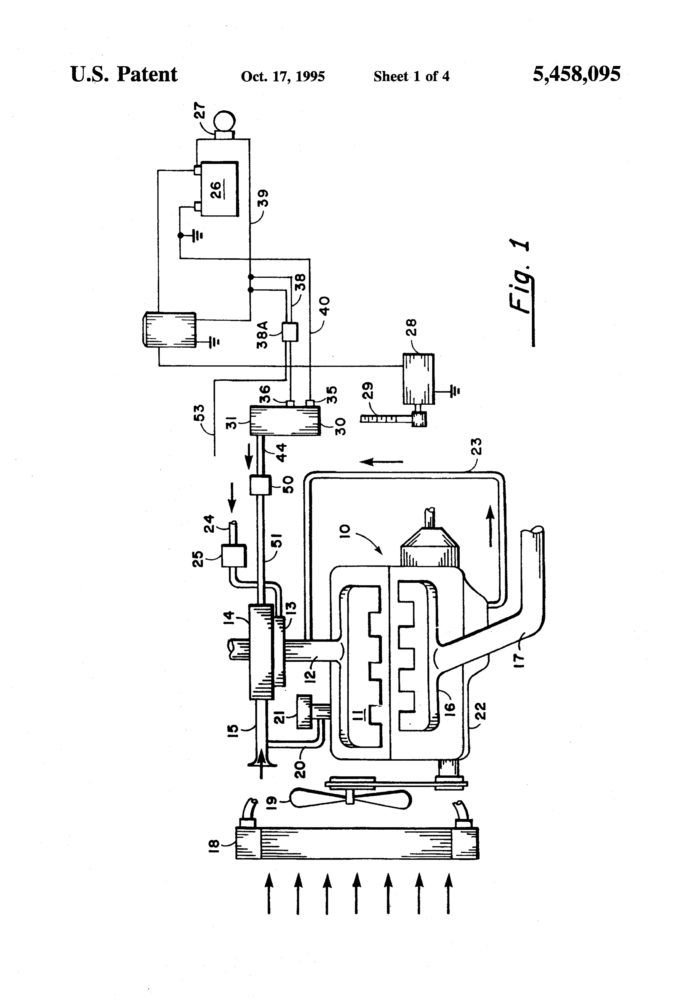
gen and oxygen generated in the electrolysis cell are with The engine also includes a battery 26 as a source of drawn by the electric pump and fed into the intake air electric potential, together with associated wiring and manifold. switching. An ignition key switch 27 is adapted to supply The pump is preferably an electric pump which is pow energy from the battery 26 to a cranking motor 28 to activate ered by being connected to a nearby vehicle battery or other a flywheel 29, which is turned over to start the engine. reliable source of electric potential. The invention includes an electrolysis canister or cell 30, In the preferred embodiment, the outlet side of the pump which provides hydrogen and oxygen gas, and a pump 50 to is connected to the air intake using a hose having a termi draw the hydrogen and oxygen gas produced thereby from O the cell 30 into the air intake 11 of the engine.
nating insert. The insert, typically formed from copper tube bent at an approximately degree angle, insures that the More particularly, the cell 30 includes a waterproof cylin hydrogen and oxygen gas outlet from the pump is in the drical casing 31, made of a chemically and electrically inert same direction as the downstream airflow in the air intake material, such as high impact plastic, tempered glass, glazed manifold.
lava, or the like. The cell 30 is not restricted to a cylindrical
Additionally, we have found that a simple low-pressure shape, but may have any suitable configuration, including pop-up relief valve positioned within the electrolysis cylin square, rectangular, or custom fitted, depending upon the der is set to open with a fairly low pressure such as one most convenient location for its installation. quarter pound/square inch is reached, adequately prevents The cell 30 also includes a cathode 35 and anode 36. A any hazard of explosion in the electrolysis cell. 20 first wire 38 electrically connects the anode 36, through a The invention provides a reliable improvement in fuel fuse box 38A, to a wire 39. The wire 39 leads through an efficiency as well as a reduction in noxious gases emitting ignition key switch 27 to connect with the positive terminal from the engine. of the battery 26.
A second wire 40 is in electrical contact with cathode 35
BRIEF DESCRIPTION OF THE DRAWINGS 25 and leads to the negative ground terminal of the battery 26, or vehicle frame, if the electrical system is grounded.
In order that the invention may be better understood, a Upon applying an electric current to the cathode and description of the invention is provided herein with refer anode 35 and 36, an electrolytic solution within the cell 30 ence to the general concepts and an illustrative embodiment generates hydrogen and oxygen gases. thereof, wherein:
FIG. 1 is a diagrammatic view of an automobile engine 30 The hydrogen and oxygen gases produced in the cell 30 showing the connection of electrolysis cell and pump of the are conducted from the cell 30 to the intake manifold 11 by present invention; the pump 50.
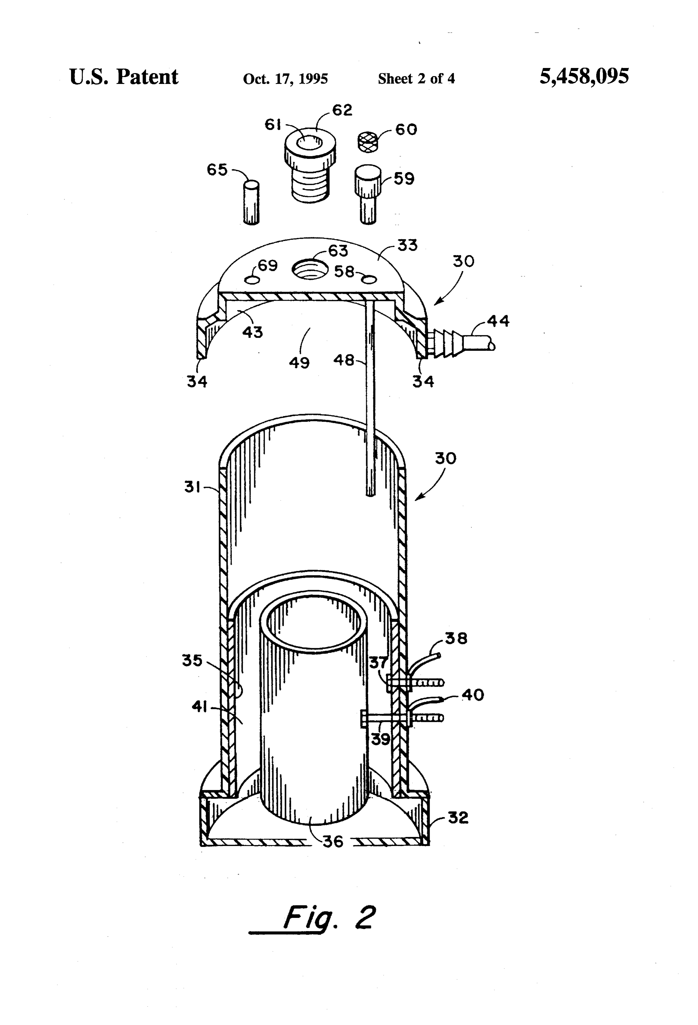
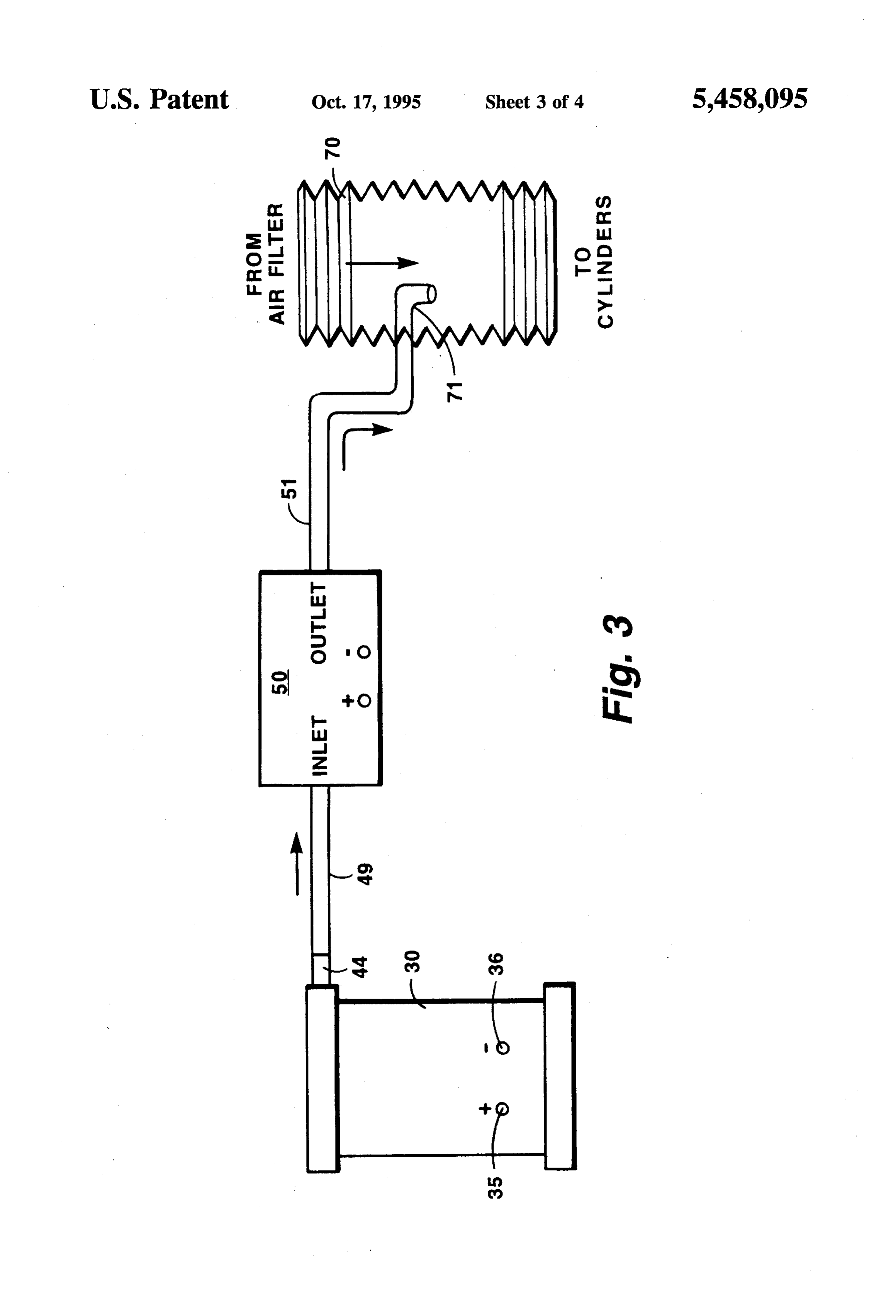
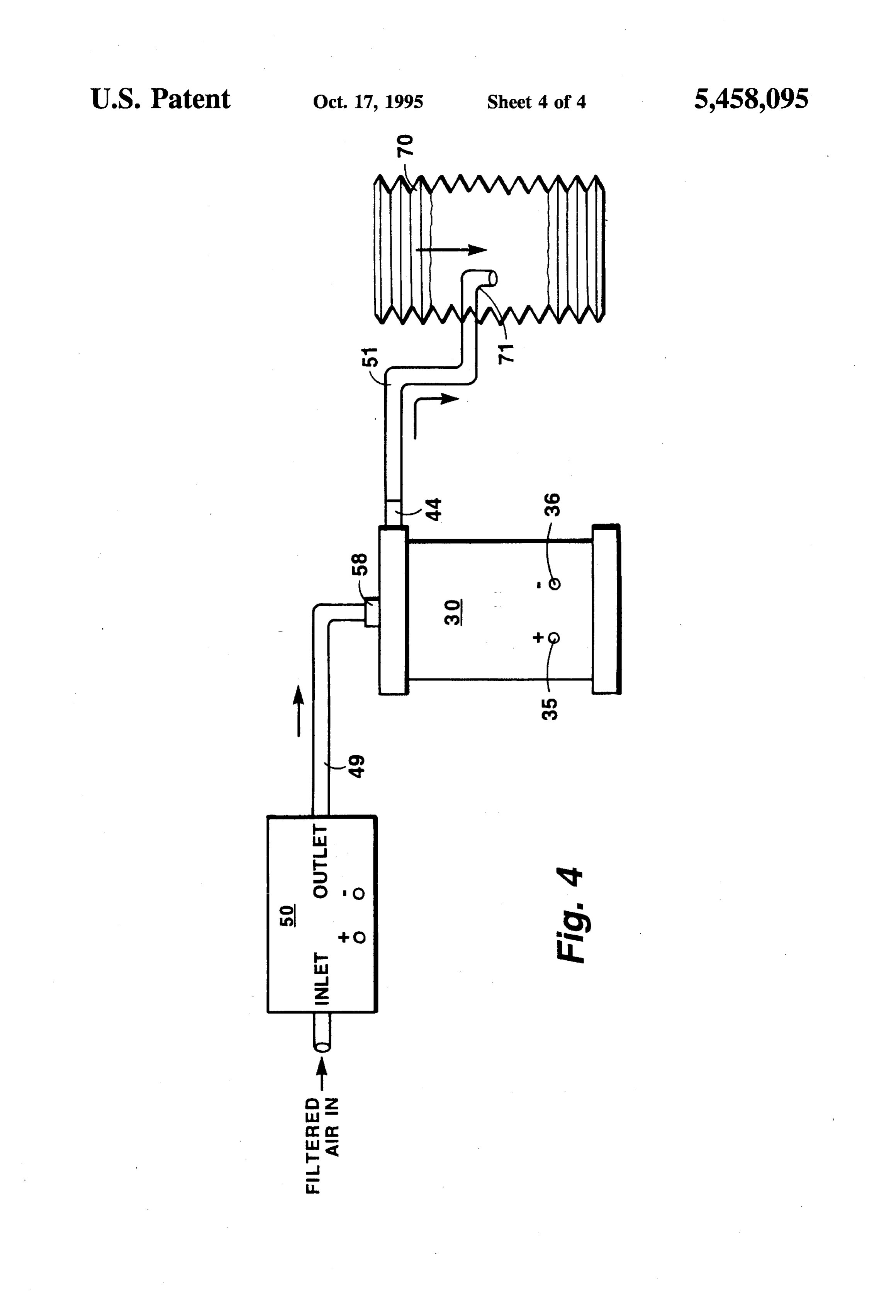
FIG. 2 is a an exploded perspective view of the electroly In the preferred arrangement, the pump 50 draws the sis cell, indicating the location of electrodes, gas accumu 35 gases out of the cell 30 through a gas outlet line 44 into a hydrogen gas flow inlet line 51. The inlet line 51 is con lation zone, gas delivery line, and the like; nected in some convenient manner to the air intake of the FIG. 3 s a diagrammatic view of the electrolysis cell, air engine, such as after the air filter 14, at the main stem 12, or pump, and air intake hose in one configuration; and in some other convenient, low operating pressure position, FIG. 4 is a similar diagramatic view of the pump elec so that the gases are presented to the intake manifold 11. In trolysis cell, and air intake hose in another configuration. 40 a turbocharged engine, for example, the inlet line 51 is positioned before the turbocharger. Alternatively, the pump
DESCRIPTION OF THE PREFERRED 50 can be arranged to pump ambient air into the cell 30, with EMBODIMENTS the gas outlet line 44 connected to the inlet line 51 of the Referring now to FIG. 1, the use of the invention in 45 engine. The resulting air pressure then forces the gas from the cell into the air intake.
connection with a carburated internal combustion engine for use in a vehicle will be described first. An internal combus Preferably, the pump 50 is powered by a reliable and tion engine in which fuel is ignited by spark plugs is shown convenient source of electric energy, such as the battery 26. as including an engine block represented at 10. As is In such an instance, a pump supply voltage 53 is electrically conventional, the engine block 10 includes a fuel intake 50 connected to the battery 26 through the fuse box 38A to the manifold 11 having a main stem 12, upon which is mounted wire 39, and the pump 50 is suitably grounded. a carburetor 13 for a hydrocarbon fuel such as gasoline. Continuous duty cycle-type pumps 50 compatible with Above the carburetor 13 is an air filter 14 having a main air the operating conditions typically expect? d within the intake port 15. The engine block 10 also has an exhaust engine compartments of automobiles, trucks, and other manifold 16 from which extends an exhaust pipe 17, as well 55 places where internal combustion engines are located are as a cooling system including a radiator 18 and a fan. 19. A readily available. One particular pump uses one or more fuel tank (not shown) supplies gasoline or other fuel through so-called duckbill valves, which insure that at any instant in a line 24 via a fuel pump 25, which is then introduced into time, the inlet port or outlet port are open, but not both at the the carburetor 13. same time, to assist in arresting back pressure through the The engine also includes a conventional positive crank 60 system such as during an engine backfire. case ventilation (PCV) system, in which a source of air is Although a carburated, gasoline powered engine is shown drawn from the air intake 15 through a tube 20 into the oil in FIG. 1, it should be understood that the invention is filler cap assembly 21, from where the air flows past rocker equally applicable to other types of internal combustion arms and push rods (not shown) into the crankcase 22. The engines such as diesels, fuel-injected engines, and the like. air and accumulated crankcase gases then enter a spring 65 It should also be understood that the invention can be used loaded regulator valve (PCV valve, not shown), through a with other than vehicle engines such as heating plants, crankcase venthose tube 23 to the main stem 12 of the intake generators, and the like, although some adaptations may be
Page 8
5 6 -
necessary in other applications. For example, in a residential A pressure relief valve 65 is also mounted within another oil furnace, the convenient electric energy source would opening 64 in the top cap 33. The valve 65 allows for the typically be a 120 volt alternating current (AC) outlet, rather escape of internal gas pressure within the cell 30. We have than a battery 26, and the air exhaust would be to a pipe or found that a fairly low pressure relief setting, such as a chimney. one-quarter pound per square inch, provides adequate pro Referring now to FIG. 2, one embodiment of the elec tection against any possible explosion hazard. trolysis cell 30 will be described in greater detail. The cell The size of the cell 30 typically varies according to the 30 includes a casing 31 having a bottom cap 32 and a top cap size of the engine to which it is attached. For example, for 33 which are securely adhered to the casing 31 in any automobiles having a four cylinder engine, a recommended suitable way. 10 size for the canister 31 is about three and one-half inches in diameter, with a height of about eight to twelve inches.
One of the caps 32 or 33 should be removable, such as a Diesel trucks typically use an eight and one-half by twenty screw-on cap, to permit cleaning and inspection of the four to thirty-six inch size.
interior of the cell 30. One type of electrolytic solution can be made by mixing The cathode 35 is formed as a stainless steel sleeve or core 15 small quantities of phosphoric acid (food grade), sodium 35, which may be formed as an inner liner for the casing 31. perborate (to supply extra oxygen), and acetanilide as a The anode 36, also formed as a cylindrical stainless steel stabilizer, in deionized or distilled water. Additives are often core, is secured concentrically of the cathode cylinder 35. desired or required. For example, in colder climates, it has The anode 36 is supported by a pair of stainless steel bolts been found that a mixture of propylene glycol should be 37 and 39 secured to the casing 31. The bolt 37 is insulated 20 added to the electrolyte 41 to prevent it from freezing. from contact with cathode 35 but is electrically connected to The quantities of these chemicals may be varied between anode 36 at one end and to electrical wire 38 at the other end. rather wide ranges, the objective being to provide reasonable The other bolt 39 is insulated from electrical contact with flow of current between the two electrodes. We have found both cathode 35 and anode 36, and acts simply as a support that for reliable operation in a small four-cylinder engine, member for holding anode 36 in place. 25 the cell 30 should be provided with enough electrolyte to The electrolysis cell 30 contains an aqueous electrolyte draw at least 4 amperes of current when in the cold state. solution 41, which is normally filled to a level 42 above the For further details of the contents of the preferred elec top of cathode 35 and anode 36. As is well known, when an trolytic solutions and the construction and operation of one electric current is applied thereto and passes through the particular cell 30, refer to U.S. Pat. No. 5,231,954, issued electrolyte solution between the electrodes 35 and 36, the 30 Aug. 3, 1993, which is hereby incorporated by reference. water in the solution is decomposed to produce hydrogen Electrolytic solutions other than those described in that and oxygen gas, which rises upwardly above the electrolyte patent, and indeed, electrolytic cells 30 which are quite level 42 and collects in a gas accumulation Zone 43. different in structure and, operation from the cell 30 shown Hydrogen and oxygen which reach the gas accumulation in FIG.2 may be used as well, as long as sufficient quantities zone 45 are thus drawn off by the pump 50 (not shown in 35 of hydrogen and oxygen are produced.
FIG. 2) through the gas outlet line 44, through a gas outlet We have found the pump 50 need not pull a particularly port 45. The gas outlet port 45 is provided typically by a strong vacuum. For example, with the smaller sized cell 30 suitable hose barb 46 which mates with an opening in the top for four cylinder automobiles, one such pump 50 should be cap 33. capable of maintaining at least approximately 2.8 liters per
An air cooling tube 48 extends from an opening 58 in the minute (l/min) flow against Zero pressure, 1.6 l/min against top cap 33 and terminates at a point below the surface 42 of one-half pound per square inch (psi), and 0.5 l/min against the aqueous electrolyte solution 41. The cooling tube assists one psi, terminating at 0 l/min at approximately 3 psi. in controlling the temperature of the solution 41 and also Another pump 50, suitable for use with larger engines, is allows an additional supply of ambient air to be drawn into capable of maintaining 5.9 l/min against 0 psi, 3.3 l/min the solution 41 to assistin liberation of hydrogen and oxygen 45 against 0.5 psi, and 2.5 l/min against 1 psi, terminating at 0 gas bubbles from the electrodes. In the case where the pump l/min at approximately 4 psi.
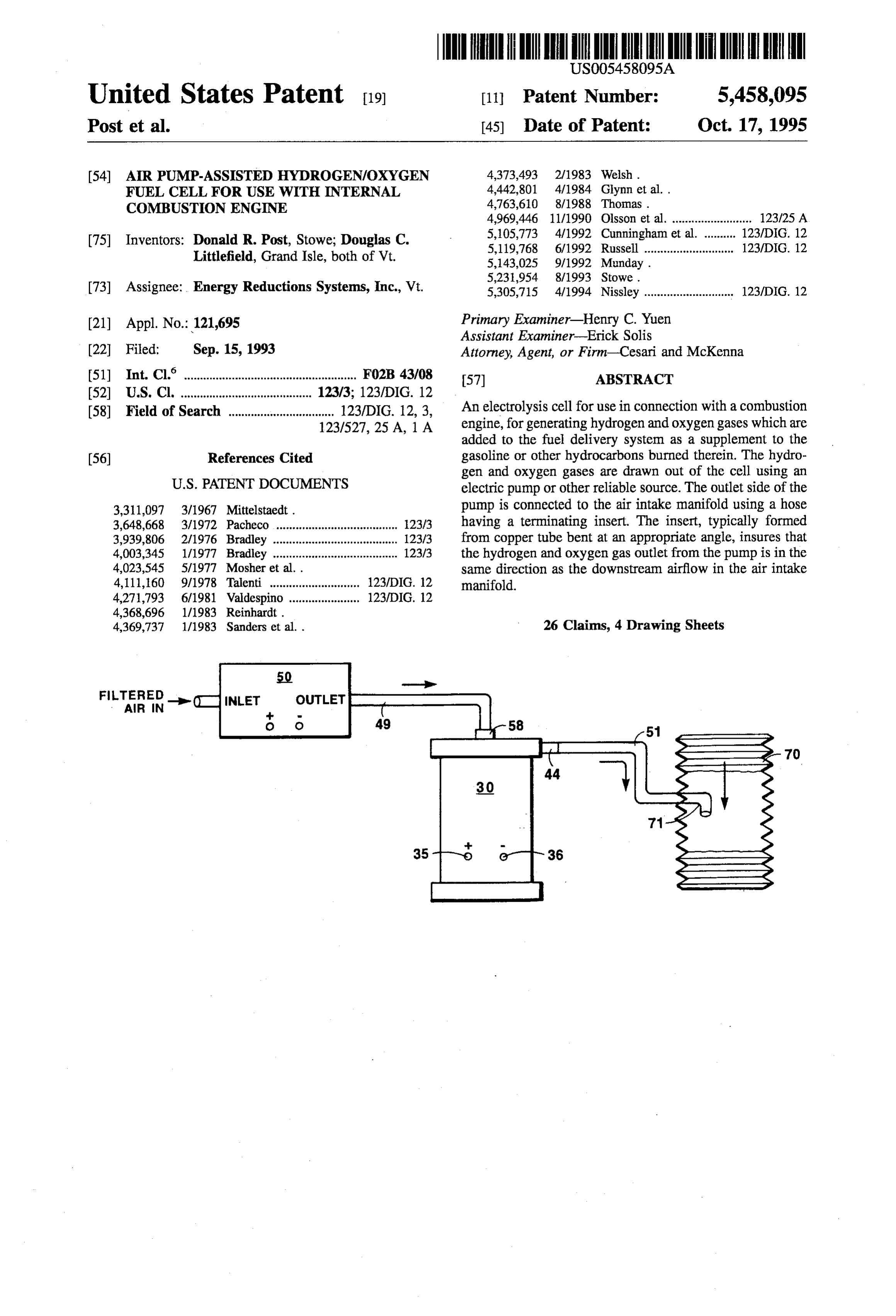
80 is arranged before the cell 30, the air cooling tube 48 FIG. 3 is a schematic view of the pump 50 and its serves as an air intake port for the cell 30. preferred use with a modern fuel injected automobile engine, An adjustable needle valve 59 is preferably inserted into 50 such as the type which has an air scoop or dam mounted near the end of the cooling tube 48, to prevent overheating of the the front of the vehicle, which is in turn connected to an air electrolytic cell 30 and to permit emission control mechanics filter to provide ambient air to an air intake manifold 11 to mix air with the accumulated hydrogen and oxygen gases (FIG. 1).
in such proportions as may be needed to conform the engine Upon application of electric potential to the cathode and operation to existing emission control regulations. 55 anode 35 and 36, the cell 30 provides hydrogen and oxygen An air filter 60 is also preferably provided in the cooling gas via the port 44 and hose 49 to the pump 50. The pump tube 48 and/or as part of the needle valve assembly to 50 thus creates a vacuum, causing hydrogen and oxygen to prevent atmospheric contaminants such as road dirt from be drawn from the cell 30 through the pump 50, to the entering the cell 30 and adversely affecting its operation. hydrogen gas inlet line 51.
A removable threaded fill plug 61 is inserted into a 60 The inlet line 51 is then secured to an air intake hose 70, threaded opening 63 in the top cap 33. The fill plug 61, preferably a intake hose which is down stream of the air which-typically includes a sight lens 62 therein, permits filter (not shown in FIG. 3). An L-shaped insert 71, formed inspection of the fluid level 42 within the cell 30. When the of a piece of copper tubing or other suitable heat-resistant electrolytic cell needs to be replenished, which in practice material bent at an appropriate angle, is placed within the has been found to be on the order of once every one to two 65 end of the inlet line 51, and protrudes into the interior of the thousand miles, the plug 61 is easily removed, and water intake hose 70. The insert 71 insures that the outflow from and/or additional electrolytic solution can be added. the pump is facing downstream, in the same direction as the
Page 9
air intake. This helps to insure that the pump 50 is not enters said gas accumulation Zone, and gas exiting said required to work against the force of the incoming air. Zone exits through said outlet port; and As previously described, the position of the cell 30 and a pump, comprising a pump inlet port which receives gas pump 50 may be reversed, with cell 30 having an inlet port exiting said outlet port and pumps the gas through a (not shown) and being placed between the pump 50 and 5 pump outlet port into the intake manifold of the engine. hydrogen gas inlet line 51. As shown in FIG. 4, the pump 50 2. The apparatus of claim 1 wherein said pump is an may be arranged to draw ambient air to its inlet port, creating electric pump operated by said source of electric potential in a positive air pressure on the cell 30, thereby causing said engine.
hydrogen and oxygen gas to be forced into the inlet line 51. 3. The apparatus of claim 1 wherein the outlet side of the The outlet of the pump 50 is connected to the opening 58 in 10 pump is connected to the intake manifold using a terminat this configuration. ing hose insert, the hose insert positioned with respect to the The invention provides a number of features which are direction of air intake to insure that outflow from the pump significant in terms of effectiveness in the field of fuel is in the same direction as the inlet airflow to the engine. consumption reduction and emission control. 4. The apparatus of claim 1 wherein said air inlet cooling Firstly, the invention is more reliable than prior devices, 15 tube includes an air adjustment needle valve to control the and provides a predictable amount of oxygen and hydrogen amount of ambient air introduced into said gas accumulation to augment the combustion of fossil fuels. Zone through said air inlet cooling tube. The invention may be used with any type of internal 5. The apparatus of claim 1 wherein a pressure relief valve combustion engine, not just those equipped with PCV emis is positioned in the electrolysis cell. sion control systems, and not just those engines which are 20 6. In a combustion engine including combustion cylin used in applications where a source of compressed air is ders; a fuel delivery means for mixing fuel with air and for readily available, such as a diesel truck. delivering said fuel/air mixture through an intake manifold The use of an electric air pump makes the hydrogen to said combustion cylinders; and a source of electrical delivery system independent of other vehicle systems, such potential energized by the operation of said engine; the as the PCV or other emission control systems, or air com 25 improvement to said engine comprising: pressors. an electrolysis cell with an aqueous electrolyte solution The operation of the system is easily confirmed. If the cell partially filling said electrolysis cell, said electrolysis 30 is drawing the desired number of amperes, and the pump cell containing at least two electrodes disposed within 50 is operating, savings in fuel and reduced emissions 30 said electrolysis cell and at least partially immersed in expected of the cell 30 will result. electrolyte solution, the electrodes being electrically connected to opposite polarities of said source of
In one test of the effectiveness of the invention, a three by electrical potential, whereby hydrogen and oxygen are eight inch cell 30 was placed in a 1987 Honda Accord LXi. generated from the water in the electrolyte solution and The prior art technique of using the PCV system to force are collected in a gas accumulation zone formed in said hydrogen gas from the cell 30 was tried first. No improve 35 electrolysis cell, and wherein said electrolysis cell has ment in gasoline mileage was observable, despite trying an inlet port and an outlet port; different amperages in the cell 30, different sized inlet lines 51, and different sized restrictions on the opening 58 for the a pump, arranged to cause gas formed in the gas accu tube 48. Upon installation of the pump 50 in the manner mulation zone to be pumped into the air intake mani shown in FIGS. 1 and 3, an immediate and sustained 13% 40 fold of the engine, said pump having an inlet port and increase in mileage was observed. an outlet port, and
Although the present invention has been disclosed in wherein the inlet port of said pump is connected to receive connection with certain preferred embodiments thereof, ambient air through an air filtration device and the variations and modifications may be made by those skilled outlet port of saidpump is connected to the airinlet port in the art without departing from the principles of the 45 of said electrolysis cell, and wherein the outlet port of invention. All of these variations and modifications are said electrolysis cell is connected to said air intake
considered to be within the true spirit and scope of the 7. A combustion engine comprising: combustion cylin present invention as disclosed in the foregoing description and defined by the claims. ders; associated pistons, crankshaft and crankcase; a hydro What is claimed is: 50 carbon fuel tank containing a primary fuel; primary fuel 1. In a combustion engine including combustion cylin pumping means, for pumping said primary fuel; primary ders; a fuel delivery means for mixing a primary fuel with fuel mixing means for mixing said primary fuel with air and air and for delivering said primary fuel/air mixture through delivering said primary fuel/air mixture through an intake an intake manifold to said combustion cylinders; and a manifold to said combustion cylinders; and a battery ener source of electrical potential energized by the operation of 55 hydrogen fueloperation gized by the of said engine; and a supplemental source comprising said engine; the improvement to said engine comprising:
an electrolysis cell containing an aqueous electrolyte an electrolysis cell comprising a body; solution and at least two electrodes disposed within an aqueous electrolyte solution partially filling said body said electrolysis cell each at least partially immersed in of said electrolysis cell and leaving a gas accumulation said electrolyte solution, said electrodes being electri 60 Zone there above in said electrolysis cell; cally connected to opposite polarities of said source of an inner stainless steel cylindrical electrode and an outer electrical potential, whereby hydrogen and oxygen are stainless steel cylindrical electrode concentrically dis generated from the water in the electrolyte solution and posed with respect to each other within said electrolysis are collected in a gas accumulation Zone formed in said cell body and at least partially immersed in said elec electrolysis cell, and wherein said electrolysis cell has 65 trolyte solution, said inner electrode being electrically an air inlet cooling robe which includes art air filter, and connected to the positive side of said battery through an an outlet port, wherein air passing through said air filter ignition key switch, and said outer electrode being
Page 10
connected to the negative side of said battery, whereby cell containing at least two electrodes disposed within when said ignition key switch is turned to an on said electrolysis cell and at least partially immersed in position, hydrogen and oxygen are generated from said electrolyte solution, the electrodes being electrically electrolyte solution and are collected in said gas accu connected to opposite polarities of said source of mulation Zone; electrical potential, whereby hydrogen and oxygen are a cooling air intake opening in the body of said electroly generated from the water in the electrolyte solution and sis cell, having an air filter disposed therein, wherein are collected in a gas accumulation Zone formed in said atmospheric air passes through said air intake and said electrolysis cell;
air filter on its way into said gas accumulation Zone, the 10 a pump, arranged to cause gas formed in the gas accu size of said opening being controlled by an air adjust mulation zone to be pumped into the air intake mani ment valve; fold of the engine; and an outlet port through which gases in said accumulation an air filtration device, arranged to cause ambient air to be Zone exit said electrolysis cell; pumped together with the gas formed in the gas accu an electric pump having electrical terminals to receive 15 mulation zone into the air intake manifold of the electric power and having inlet and outlet ports, the engine.
terminals of the electric pump being connected to the 16. The apparatus of claim 15 wherein said pump is an positive and negative sides of said battery; electric pump operated by said source of electric potential in a first hydrogen/oxygen delivery line connected at one said engine.
end through the body of said electrolysis cell into said 20 17. The apparatus of claim 15 wherein the electrolyte is in gas accumulation zone in said electrolysis cell and communication with the atmosphere through an air cooling connected at the other end to said inlet port of said tube.
electric pump; 18. The apparatus of claim 17 wherein said cooling tube a second hydrogen/oxygen delivery line connected at one includes an air adjustment needle valve. end to the outlet of said electric pump and connected at 25 19. The apparatus of claim 15 wherein a pressure relief the other end to said intake manifold, valve is positioned on the electrolysis cell. whereby hydrogen and oxygen generated in said supple 20. The apparatus of claim 15 wherein said electrolysis mental hydrogen fuel source are withdrawn by said cell has an inlet port and an outlet port and said pump has pump and fed into said intake manifold. an inlet port and an outlet port, and 8. The apparatus of claim 7 wherein the electrolyte is in 30 wherein the inlet port of said pump is connected to receive communication with the atmosphere through an air cooling ambient air through an air filtration device and the tube. outlet port of said pump is connected to the airinlet port 9. The apparatus of claim 8 wherein said cooling tube of said electrolysis cell, and includes an air adjustment needle valve. wherein the outlet port of said electrolysis cell is con 10. The apparatus of claim 7 wherein a pressure relief 35 nected to said air intake manifold. valve is positioned on the electrolysis cell. 21. The apparatus of claim 20 wherein the outlet port of 11. The apparatus of claim 7 wherein the outlet port of said electrolysis cell is connected to the air intake manifold said electrolysis cell is connected to the air intake manifold using a terminating hose insert, the hose insert positioned using a terminating hose insert, the hose insert positioned with respect to the direction of air intake to insure that with respect to the direction of air intake to insure that 40 outflow is in the same direction as the inlet airflow to the outflow is in the same direction as the inlet airflow to the engine.
engine. 22. The apparatus of claim 20 wherein the outlet port of 12. The apparatus of claim 7 wherein the outlet port of said electrolysis cell is connected to said intake manifold at said electrolysis cell is connected to said intake manifold at 45 a position adjacent an air filter assembly positioned above a aposition adjacent a carburetor air filter assembly positioned carburetor.
above a carburetor. 23. The apparatus of claim 20 wherein said engine has an 13. The apparatus of claim 7 wherein said engine has an air filter and the outlet port of said electrolysis cell is air filter and the outlet port of said electrolysis cell is connected to said intake manifold at an air intake hose connected to said intake manifold at an air intake located located after the air filter. after the carburetor air filter, 50 24. The apparatus of claim 20 wherein the outlet port of 14. The apparatus of claim 7 wherein the outlet port of said electrolysis cell is connected is through a fitting adapted said electrolysis cell is connected through a fitting adapted to said intake manifold.
to said intake manifold. 25. The apparatus of claim 15 wherein said pump includes 15. In a combustion engine including combustion cylin an inlet and an outlet, wherein said inlet receives hydrogen ders; a fuel delivery means for mixing fuel with air and for 55 and oxygen from said gas accumulation Zone and pumps the delivering said fuel/air mixture through an intake manifold hydrogen and oxygen into the air intake manifold. to said combustion cylinders; and a source of electrical 26. The apparatus of claim 15 wherein said filtration potential energized by the operation of said engine; the device is located in an ambient air inlet line which provides improvement to said engine comprising: filtered ambient air to said gas accumulation Zone. an electrolysis cell with an aqueous electrolyte solution 60 partially filling said electrolysis cell, said electrolysis k . . .
Provenance
- Collection
- Cited prior art
- Original PDF
- patentimages.storage.googleapis.com →
- Filed
- 1993-09-15
- Pages
- 10
- Method
- pdftotext (the PDF's own text layer) + pdftoppm 300dpi page scans
- Source
- Google Patents bibliographic record
- Granted
- 1995-10-17
- Inventors
- Donald R. Post; Douglas C. Littlefield; Energy Reductions Systems Inc
- Transcribed from
- patentimages.storage.googleapis.com →