patent · US5634341
System for generating hydrogen
3 June 1997
Page 1
United States Patent (19) 11 Patent Number: 5,634,341 Klanchar et al. 45 Date of Patent: Jun. 3, 1997 54 SYSTEM FOR GENERATING HYDROGEN 4,698,974 10/1987 Wood.
75) Inventors: Martin Klanchar; Thomas G. Hughes, 4,851,722 7/1989 Zauderer. both of State College, Pa. 5,117,635 6/1992 Blau.
73) Assignee: The Penn State Research Foundation, FOREIGN PATENT DOC S University Park, Pa. 27626 7/1977 Japan ..................................... 423/657 21 Appl. No.: 566,486 Primary Examiner-Wayne Langel 21 Appl. No 4 Attorney, Agent, or Firm-Thomas J. Monahan
4, 1995 57 ABSTRACT
Related U.S. Application Data A process and apparatus are disclosed for generating hydro gen gas from a charge of fuel selected from the group 63 Continuation of Ser. No. 189,525, Jan. 31, 1994, abandoned. consisting of lithium and alloys of lithium and aluminum. [51] Int. C. ... C01B 3/08; F01K 25/06 The charge of fuel is placed into an enclosed vessel, then 52 U.S. Cl. ......................... 60/673; 60/39.12; 423/657; heated until it is molten. A reactant consisting of water is 423/DIG. 12; 429/20 introduced into the vessel, as by spraying from a nozzle, for 58) Field of Search ............................ 60/673; 423/657, reaction with the charge of fuel resulting in the production 423/DIG. 12 of hydrogen gas and heat which are withdrawn from the vessel. Prior to initiation of the process, an inert gas 56 References Cited atmosphere, such as argon, may be imparted to the interior of the vessel. A sufficiently large mass flow of the reactant
2,706,890 4/1955 Schmidt. diminution of flow resulting from the formation on the 3,353,349 11/1967 Percival. nozzle of fuel and chemical compounds of the fuel. Opti 3,413,801 12/1968 Meijer et al.. mum charges of the fuel are application specific and the 3,508,394 4/1970 De Nagel et al.. ranges of the constituents are dependent upon the particular 3. Ag: tal passesas A at 800 000 423/657 use of the system. The process and apparatus of the inven Y say erry et al. . tedi nki o 3,975,913 8/1976 Erickson. tion may be Eat into a Rankine cycle engine or into 3,985,866 10/1976 Oda et al. ............................... is a hydrogen oxygen fuel cell system.
4,643,166 2/1987 Hubele et al.. 9 Claims, 4 Drawing Sheets
stars arr trix risis
Page 2
Drawing sheet — no readable text.
Page 3
Drawing sheet — no readable text.
Page 4
Drawing sheet — no readable text.
Page 5
Drawing sheet — no readable text.
Page 6
SYSTEM FOR GENERATING HYDROGEN tion chamber may form a "frost” or crust on the coolest surfaces present. These cool surfaces will ordinarily be heat
GOVERNMENT SPONSORSHIP transfer surfaces where it is desired to transfer heat from the chemical reaction for utilization in a steam or vapor pressure
This application is a continuation of application Ser, No. 5 Rankine 08/189,525 filed on Jan. 31, 1994, abandoned. cycle engine. Such a crust on the heat transfer surfaces will ordinarily have a relatively high insulation
This invention was made with Government support under value in comparison with the molten fuel. As a result, the Contract NO0039-88-C-0051 awarded by the U.S. Depart crusted reaction products themselves progressively inhibit ment of the Navy. The Government has certain rights in this heat transfer from the reaction chamber to the engine. invention. 10 One approach aimed at solving the problem just men BACKGROUND OF THE INVENTION tioned is disclosed in U.S. Pat. No. 4,698,974 to Wood. In the Wood disclosure, a fuel is reacted with water in the 1. Field of the Invention absence of oxygen gas to produce heat and hydrogen gas. The present invention relates generally to hydrogen gas The heat from this reaction issued to produce water steam. generating systems and, more particularly, to a system for 15 The hydrogen gas is burned with oxygen gas in a separate the generation of hydrogen gas resulting from the reaction of second reaction chamber to produce superheated steam. The molten lithium or lithium alloy fuel with water in a con steam from the first reaction chamber is used as a coolant tained vessel. and diluent in the second reaction chamber so that steam 2. Discussion of the Prior Art flowing from the second reaction chamber to a turbine, or 20 other expander, has a metallurgically acceptable tempera
The hydrogen gas generator reactor of the present inven tion is one of the key energy producing components of a ture.
Rankine cycle vapor pressure or steam engine, for example, A shortcoming of the Wood invention, however, is that a which obtains its driving heat energy from a chemical hydrogen gas bearing reaction intermediate is formed which reaction other than the usual combustion of fuel with oxygen 25 initially partially prevents the evolution of the hydrogen gas from the air. The theoretical possibility of utilizing the from the first reaction chamber. As the reaction progresses, reaction energy of a reactive metal fuel such as aluminum, the reaction intermediate further reacts to release the bound magnesium or lithium and alloys or hydrides of these and hydrogen. The result is that over the period of the reaction, similar reactants, with an “oxidizer” such as hydrogen the rate of hydrogen gas production is at first relatively low, peroxide, Freons, sulfur hexaflouride, water and others, has 30 reaches a stable plateau, and then raises above the plateau as been recognized for many years. However, the technical the fuel supply is consumed.
difficulties and conflicts standing between a theoretical A consequence of this nonuniform rate of hydrogen gas construction of such a power system and a practical appa production is that the power output of the Rankine cycle ratus which is functional outside of the laboratory are legion. steam engine is relatively low initially and cannot be By way of example, many of the fuel-reactant combina 35 increased until the hydrogen gas production rate of the tions proposed in the past have required that the fuel be chemical reaction chamber increases. Understandably, this raised above ordinary ambient temperatures in order to sluggish initial power output of such a system is undesirable permit reaction with the reactant. Such a heating require in almost every prospective application. Additionally, the ment necessitates that some heating means, such as electrical nonuniform rate of hydrogen gas production creates many heating coils or pyrotechnic chemicals be provided. In the 40 difficulties in controlling the power output level of the former case, a significant start-up delay is incurred while a Rankine cycle engine.
portion or all of the fuel is raised to reaction temperature. In An improvement on the Wood system is presented in U.S. the latter case, the pyrotechnic chemicals, which are or may Pat. Nos. 4,643,166 and 4,730,601 to Hubele et all which, be considered to be low velocity explosives, present the according to one aspect, provides a two-part fuel composi possibility of damaging the interior of the reaction chamber 45 tion including a first or main fuel part of magnesium and and escape of highly reactive or toxic fuels. Such pyrotech aluminum in a molar ratio of 1:2, respectively. The second nic heating chemicals also frequently produce a quantity of or starter fuel part is composed of lithium hydride, magne gaseous reaction products which must be contained within sium and aluminum in equal molar ratio. On a weight basis, the reaction chamber, or else vented therefrom while pre the starting fuel composition and main fuel composition are venting loss of fuel. 50 presented at a ratio of about 1:4. In the reaction chamber, the Another undesirable aspect of many previously proposed above-outlined fuel is present in the form of prealloyed fuel-reactant systems is that intermediate reaction products powders produced, for example, from condensed vaporized or end reaction products are formed which on the one hand or atomized metal. The reaction chamber structure provides inhibit further progress of the reaction between the fuel and water in addition to heat transfer means, a means for introducing reactant or, on the other hand, freeze at a temperature higher 55 into the chamber for reaction with the fuel. than the desired reaction chamber temperature. In the one In one embodiment, the means for introducing water case, complex structures and methods have been proposed to comprises a manifold with foraminous distribution tubes cure the shortcoming by removing the intermediate or final depending in the fuel. The distribution tubes are immedi reaction product from the reaction chamber. Alternatively, ately surrounded by a comparatively thin layer of the only a portion of the fuel could be brought into contact with starting fuel part. The main fuel part is received within the the reactant so that reaction products could not contaminate reaction chamber around the distribution tubes and layer of the remaining fuel. Again, complexity is increased. starting fuel part. w The problem of the reaction intermediates or final prod In another embodiment, the main fuel part is disposed in ucts freezing attoo high a temperature presents the difficulty a lower portion of the reaction chamber. In an upper portion that the reaction chamber may soon become filled with a 65 of the reaction chamber is disposed an appropriate quantity "slush” of frozen reaction products in a slurry of moltenfuel. of the starting fuel part and, in this instance, the reaction Similarly, the high-freezing constituents present in the reac chamber includes a water inlet nozzle disposed in an upper
Page 7
part of the reaction chamber above both the starting and vessel. Prior to initiation of the process, an inert gas main fuel parts. Preferably, the water nozzle is separated atmosphere, such as argon, may be imparted to the interior from the fuel during operation of the reaction chamber and of the vessel. A sufficiently large mass flow of the reactant engine. through the nozzle is maintained to assure that there be no Aprimary advantage of the patented system as mentioned diminution of flow resulting from the formation on the therein is the stated absence of any need or requirement to nozzle of fuel and chemical products of the fuel. Optimum provide fuel preheating before the reaction chamber is charges of the fuel are application specific and the ranges of operational. According to a further stated advantage, the the constituents are dependent upon the particular use of the introduction of simple water is all that is required to initiate system. The process and apparatus of the invention may be operation of the reaction chamber to produce both heat and 10 incorporated into a Rankine cycle engine or into a hydrogen a supply of hydrogen. This latter feature is said to be of oxygen fuel cell system.
particular advantage when the invention issued in connec A primary object of the present invention, then, is to tion with a water borne vehicle. provide a system for the production of hydrogen gas which However, the Hubele etal. invention exhibits a number of is, compact, clean, efficient, controllable, and economical. drawbacks. Specifically, the disclosures in the Hubele et al. 15 Another object of the present invention is to provide such patents relate the use of two separate and distinct fuels and, a system which generates hydrogen from a charge of fuel furthermore, do not require that the fuels be raised in selected from a group consisting of lithium, and alloys of temperature to a molten mass as does the present invention. lithium and aluminum, and alloys of lithium and aluminum Indeed, those patents stress the desirability of a reaction 20 and lithium hydride, and alloys of lithium and lithium which is performed at common ambient temperatures and hydride.
which do not require preheating or pyrotechnic chemicals to Another object of the present invention is the provision of be used in starting the reaction. While the Hubele et al. such a system which can be utilized in a number of patents imply that there is a strategic advantage to starting at applications, in one instance as a component for a Rankine room temperature and to reacting a starting charge first and, 25 cycle engine and, in another instance, as a component in a Subsequently, the main fuel, they also state that the entire hydrogen oxygen fuel cell system.
fuel mass will melt in very short order. In effect, what will Yet a further object of the invention is to provide such a occur is that the operator of the Hubele et al. system will not system in which a maximum output of energy is achieved be able to control the local reaction to first use the start charge with the result that a molten mass will be achieved 30 from a given volume of fuel.
with only one fuel, not two, and the stated claim of a Other and further features, advantages, and benefits of the regulated, flat, hydrogen gas production will not be invention will become apparent in the following description achieved. taken in conjunction with the following drawings. It is to be understood
Other patents of interest include U.S. Pat. No. 3,353,349 following detailed that the foregoing general description and the to Percival and U.S. Pat. No. 5,117,635 to Blau. Percival 35 tory but are not todescription are exemplary and explana discloses a closed cycle thermal engine provided with a accompanying drawings which areofincorporated be restrictive the invention. The combustion system for heating the working gas thereof. The constitute a part of this invention, illustrate one inof and the combustion system produces nongaseous byproducts and embodiments of the invention and, together with the operates at substantially constant volume by employing description, serve to explain the principles of the invention molten lithium or sodium as a fuel and certain gaseous in general terms.
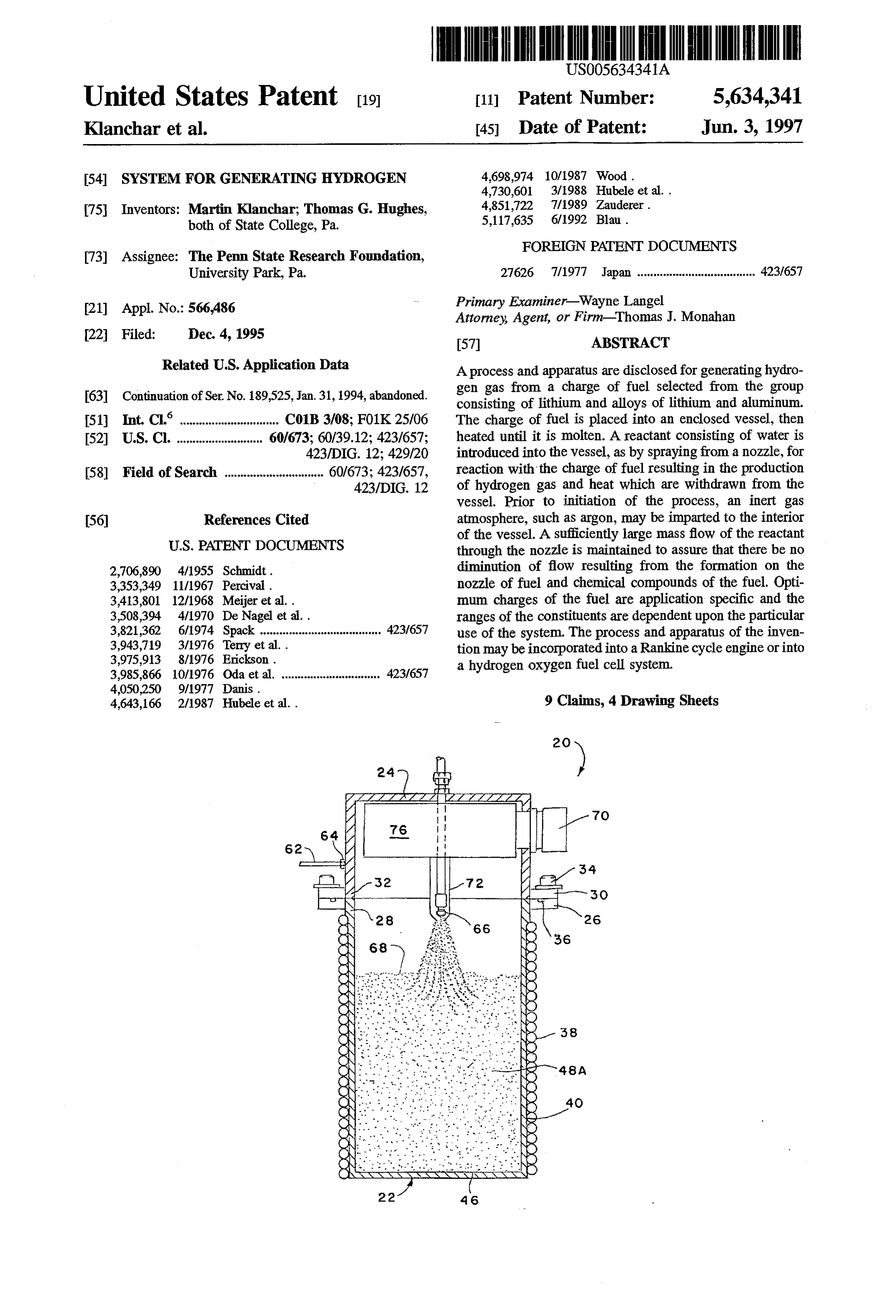
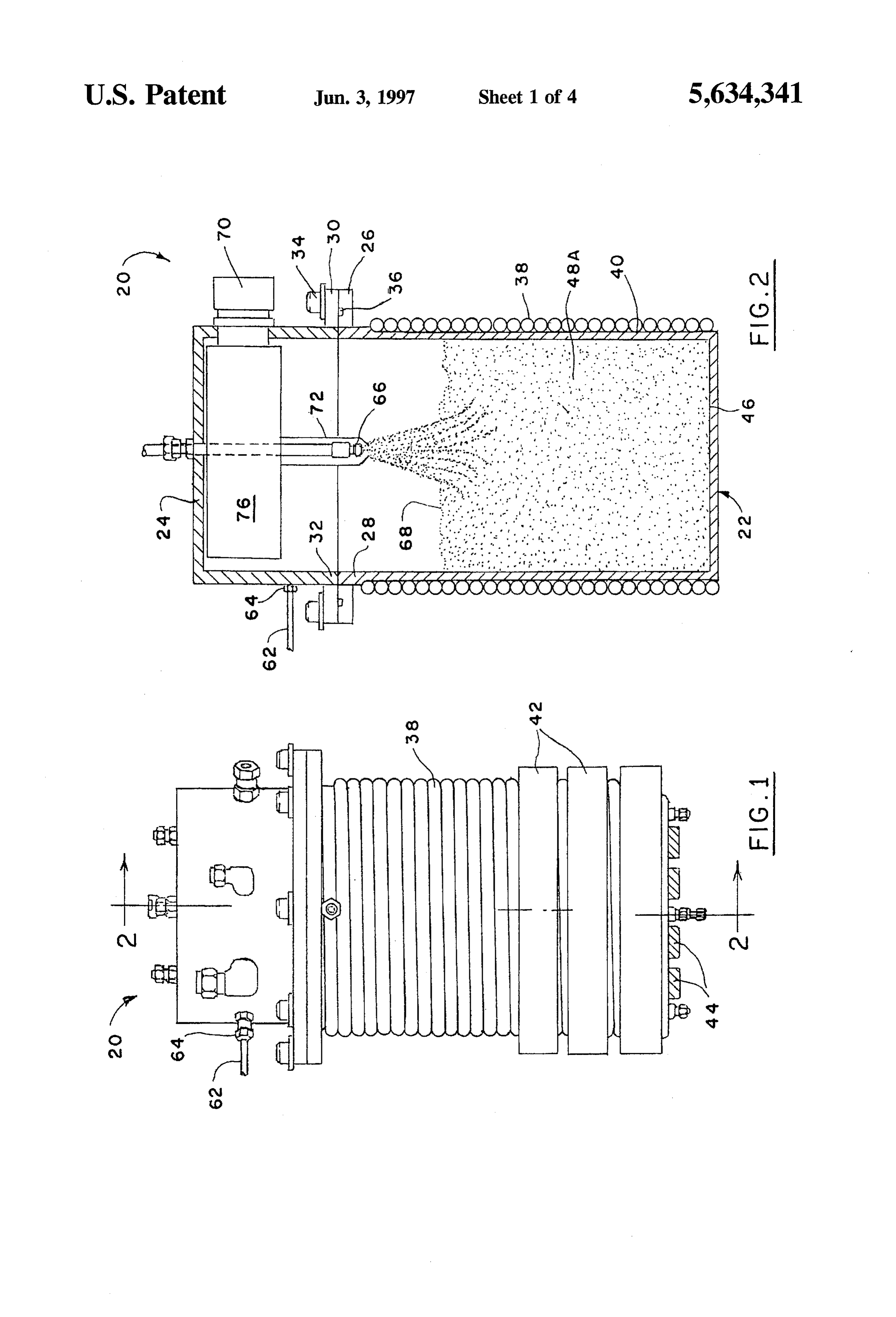
nonhydrogen containing Freon-type fluorocarbon com the disclosure. Like numerals refer to like parts throughout pounds as the oxidizer. Blau describes an open-cycle Rank ine steam engine. One of the energy-producing components BRIEF DESCRIPTION OF THE DRAWINGS of the engine does utilize molten lithium as a fuel. However, hydrogen gas is not generated anywhere within the system. 45 FIG. 1 is a side elevation view illustrating a reaction vessel embodying the present invention;
SUMMARY OF THE INVENTION
FIG. 2 is a cross section view, in elevation, taken gener
It was in light of the prior art as just described that the ally along line 2-2 in FIG. 1;
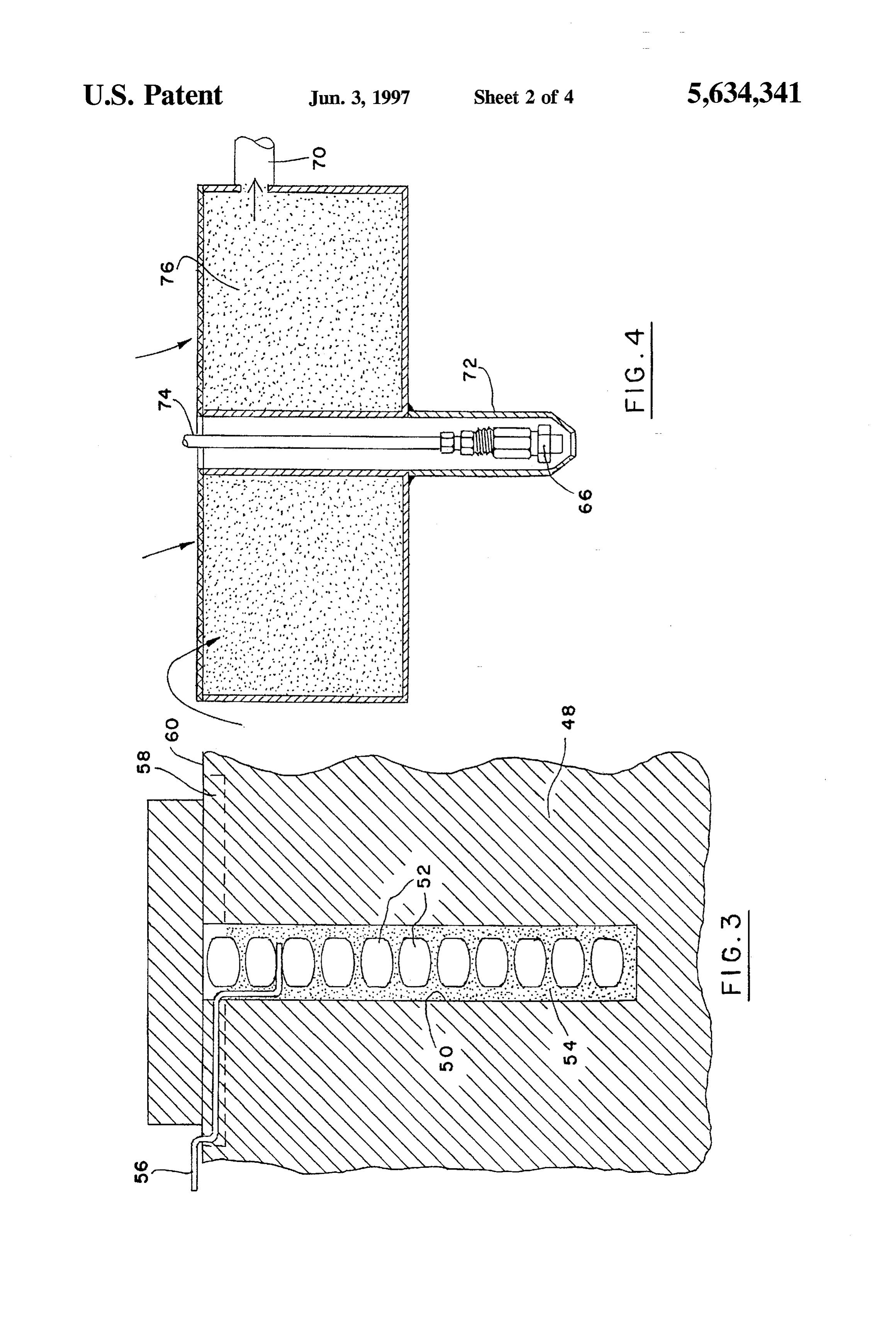
present invention was conceived and has now been reduced FIG. 3 is a detail cross section view of a pyrotechnic to practice. The present invention, then, relates to a process 50 arrangement for heating fuel in the reaction vessel of FIGS. and to apparatus for generating hydrogen gas from a charge 1 and 2;
of fuel selected from the group consisting of lithium, and alloys of lithium and aluminum, and alloys of lithium and ofFIG. 4 is a detail cross section view to provide more detail a component illustrated in FIG. 2;
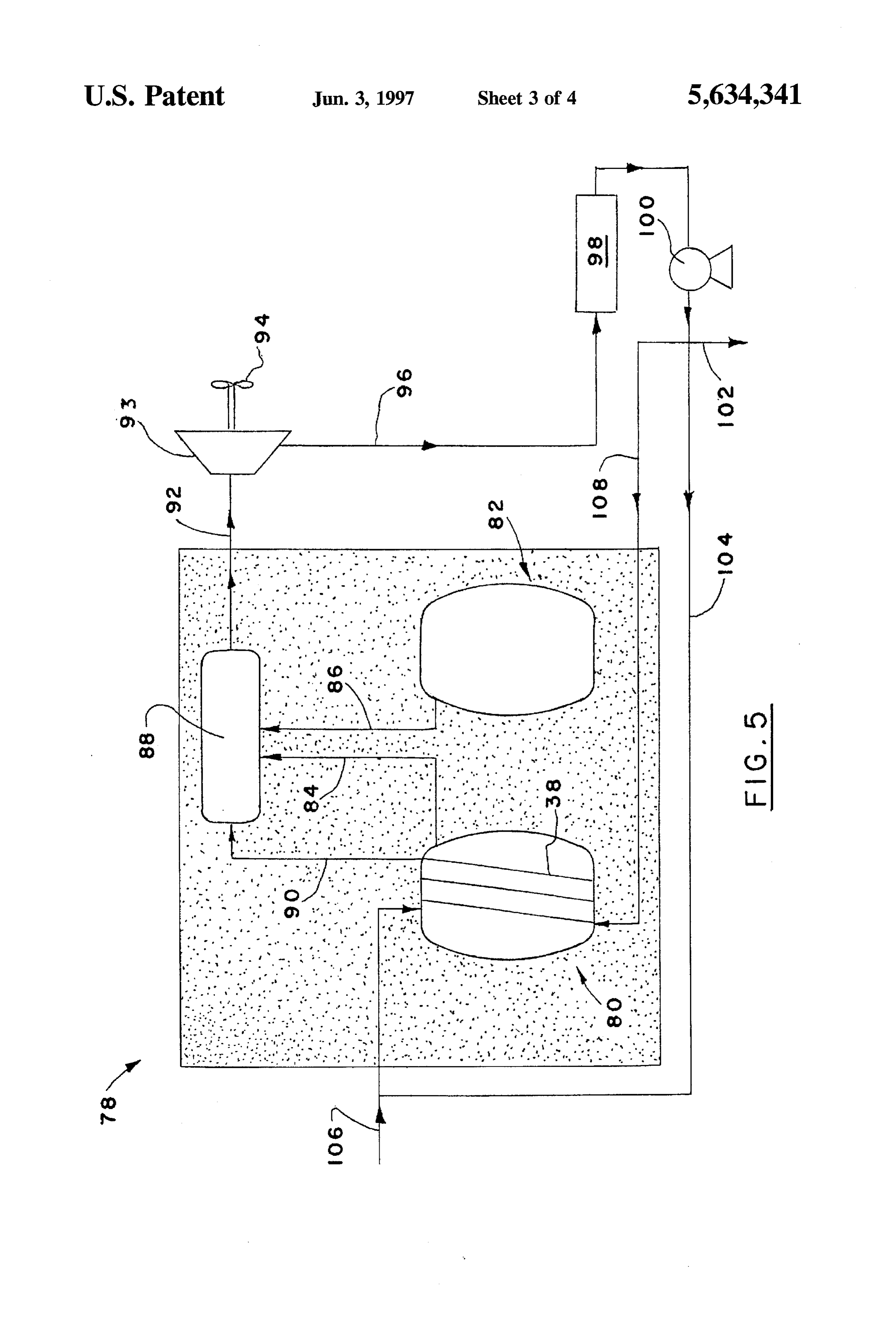
aluminum and lithium hydride, and alloys of lithium and FIG. 5 is a schematic representation of a Rankine cycle lithium hydride. These alloys were selected primarily 55 engine because their reaction with water produces relatively large FIGS. 1utilizingand 2;
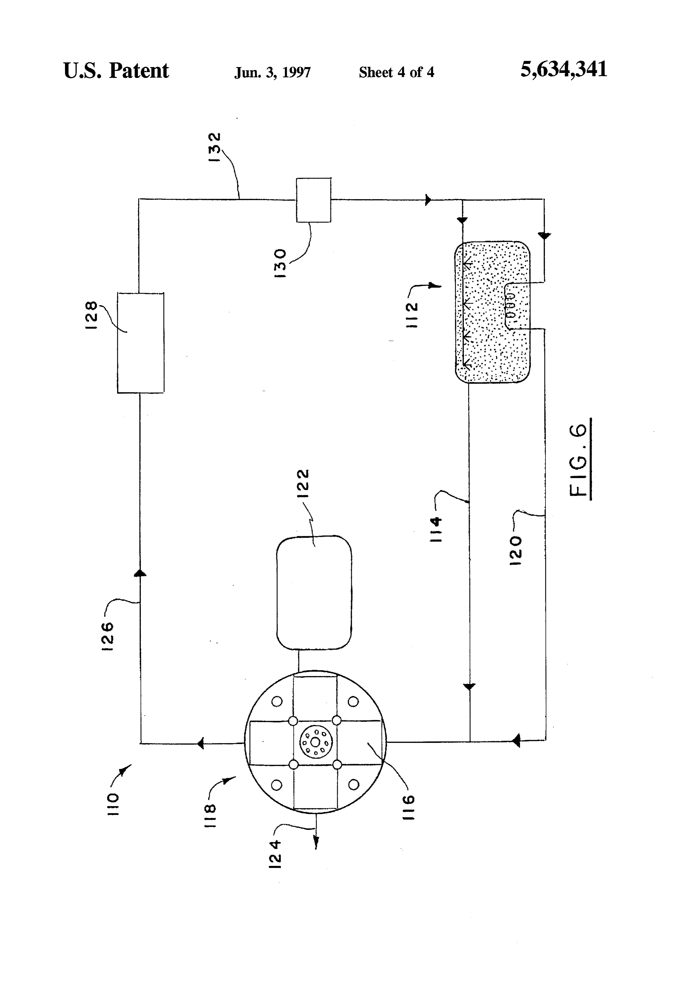
the hydrogen generating reaction vessel of and amounts of hydrogen gas and heat per storage (reactor vessel) volume. In addition, the kinetics of the reaction are FIG. 6 is a schematic representation of a hydrogen oxygen very fast-essentially instant and irreversible. Also, post-run fuel cell system utilizing the hydrogen generating reaction cleanout of the vessel is relatively safe and easy since the vessel of FIGS. 1 and 2.
remaining products of reaction (metal oxides) are typically DETALED DESCRIPTION OF THE nontoxic and water soluble.
PREFERRED EMBODIMENT
The charge of fuel is placed into an enclosed vessel, then heated until it is molten. A reactant consisting of water is Turn now to FIGS. 1 and 2 which illustrate a reaction introduced into the vessel, as by spraying from a nozzle, for 65 vessel 20 which can be utilized to generate hydrogen gas reaction with the charge of fuel resulting in the production according to the present invention. The reaction vessel 20 is of hydrogen gas and heat which are withdrawn from the composed of a material which is relatively inert, that is,
Page 8
would not take part in any reactions necessary for the determined according to the hydrogen and heat generation generation of hydrogen gas. Appropriate materials include requirements of the Rankine or hydrogen oxygen fuel cell various stainless steels and other metallic superalloys. In any systems.
event, the reaction vessel 20 comprises a base container 22 Prior to operation of the reaction vessel 20, it may be which is for the purpose of supporting the reactant materials desirable to purge the interior of the vessel, after it is sealed, and alid 24 which matingly connects with the base container with an inert gas for the purpose of removing oxygen which, to sealingly enclose the reaction vessel. The base container if present, would have an undesirable effect on the reaction. 22 and lid, 24 are preferably generally cylindrical. The For this purpose, a line 62 is illustrated in FIGS. 1 and 2 former has an integral annular flange 26 adjacent its upper connected via a fitting 64 to the lid 24 for introducing a most rim 28 and the lid 24 has an integral annular flange 30 10 pressurized inert gas such as argon to the interior of the adjacent its lowermost rim 32. The flanges 26, 30 are reaction vessel 20. Flow of the inert gas is not continuous. matingly engageable and can be locked together by a When water injection into the vessel is begun, flow of the plurality of circumferentially spaced fasteners 34. Fluid tight inert gas is terminated.
integrity between the flanges 26, 30 is achieved by reason of While purging continues, the heating operation begins a circumferentially extending O-ring seal 36 interposed 15 using any, or any combination, of the heating mechanisms between the flanges. already described, or any other manner of heating which The reaction vessel 20 thus described is, indeed, a pres may be suitable for the purpose. Heating continues until the sure vessel capable of safely containing reactions which fuel is molten which occurs at approximately 600°F. At this develop operating pressures in excess of 100 psia. point, reactant consisting of water is introduced into the Cooling plumbing is provided in the form of spiral tubing 20 vessel via a nozzle 66 directed at a surface 68 of the now 38 which envelopes the peripheral external surface 40 of the molten fuel 48A as illustrated in FIG. 2. base container 22. It is preferably welded into place and Indeed, the nozzle 66 is so directed at the surface of the enables flow of cooling water at arapid rate from an ambient molten fuel 48A that the water spray penetrates the Surface source from the uppermost regions of the base container to 25 and causes agitation of the mass of the molten fuel. The its lowermost regions. reaction of water and fuel results in the production of The reaction vessel 20 also has provision for heating its hydrogen gas and heat. Because the reaction between the interior. This may be achieved in a number of different ways. fuel and the reactant, or water, is an exothermic one, once For example, a propane burner (not shown) may be posi the reaction has begun, it is no longer necessary to continue tioned beneath the base container 22 and ignited when 30 with the operation of the heaters 42, 44 and their operation appropriate. In another instance, electrical band heaters 42, is then discontinued. Heat is withdrawn from the reaction 44 may be utilized. In this instance, a plurality of cylindrical vessel 20 by means of water flow through the spiral tubing band heaters 42 may be suitably mounted on the peripheral 38, and exhaust tubing 70 is employed for withdrawing the exterior of the base container 22 at its lowermost regions. hydrogen gas from the interior of the reaction vessel 20. Similarly, strip heaters 44 are suitably mounted to a bottom 35 Because of the intense heat within the reaction vessel, as wall 46 of the base container 22. well as the violent agitation caused by the reaction, a Yet another manner of heating, as generally illustrated in protective cylindrical shield 72, preferably made of stainless FIG. 3 may be employed either by itself or in conjunction steel, surrounds a water inlet conduit 74 and the nozzle 66 with one of the heating techniques just described. In this to prevent their degradation.
instance, solid fuel 48, typically in block form, placed in the Since the reaction within the vessel 20 is vigorous and base container 22, is provided with its own pyrotechnic combustion-like, the hydrogen gas so produced leaves the devices which provide considerable amounts of heat in a vessel via the exhaust tubing 70 at a very high velocity. This nearly instantaneous manner. In this instance, a plurality of causes entrainment of unreacted fuel and solid products, for core holes 50 are formed into the block of the fuel 48. A example, oxides and hydroxides of lithium and aluminum plurality of Alclo brand (a mixture of aluminum and potas 45 (in the event aluminum is in the starting fuel) in the gas sium perchlorate) pellets 52 are inserted into each core hole stream which must be removed before it leaves the vessel. 50. The pellets are spaced apart and supported in a bed or For this reason, it is important to provide a filter 76 which matrix. 54 of thermite, also known as a mixture of aluminum is integral with the cylindrical shield 72 and is interposed and copper oxide. between the interior of the vessel and the exhaust tubing 70. An igniter wire 56 extends from a region beyond the fuel 50 The hydrogen gas which exits the reaction vessel 20 is block 48 and, indeed, extends through the interface between thereby assured of having a high level of purity. the lid 24 and the base container 22 to a location outside of The reaction vessel 20 for generating hydrogen can be reaction vessel 20. An innermost end of the igniter wire 56 employed in a variety of systems. In one instance, for is preferably positioned between a pair of the pellets 52 example, it may have application in a Rankine steam cycle within the bed 54 of thermite. A vent groove 58 may be 55 power plant 78 used for underwater propulsion purposes. provided at an uppermost surface 60 of the fuel block 48 in Such a system is illustrated in FIG. 5. It comprises a order to vent the combustion products of the pyrotechnic hydrogen generator 80 generally of the construction of the charge just described. reaction vessel 20 and an oxygen generator 82 which may The block of fuel 48, for purposes of the invention, is be, for example, generally of the construction disclosed in selected from the group consisting of lithium, and alloys of commonly assigned copending application Ser. No. 08/132, lithium and aluminum, and alloys of lithium and aluminum 021 and filed Oct. 5, 1993, now U.S. Pat. No. 5,376,352. As and lithium hydride, and alloys of lithium and lithium indicated in FIG. 5, hydrogen gas from the hydrogen gen hydride. In each instance, a wide range of compositions of erator 80 and oxygen gas from the oxygen generator 82 flow the components of the fuel may be utilized when other than via lines 84, 86, respectively, to a burner 88, along with low 100% lithium. The lithium and lithium-alloy fuel mixtures 65 temperature steam which travels via a line 90 from the spiral provide exceptional energy density interms of hydrogen and tubing 38 in the burner 88. The hydrogen gas and the oxygen heat production. The exact composition of the alloy fuel is gas are combusted to generate super heated steam which
Page 9
travels via line 92 to a turbine 93 which produces power, for 3. A process for generating hydrogen gas as set forth in example, to drive a shaft and propeller 94. Exhaust lower claim 2 energy steam is directed from the turbine 93 via line 96 to wherein step (e) includes the step of: a condenser 98 which operates to change its state into water.
Afeed water pump 100 operates to cycle the water through 5 (f)vessel. imparting an argon atmosphere to the interior of the the power plant. Excess water from the feed water pump 4. A process for generating hydrogen gas as set forth in may be dumped via a line 102 while reactant water may be claim 1 delivered to the hydrogen generator 80 via a line 104 along wherein step (c) includes the step of: with starting water from a line 106, and cooling water may (f) maintaining a sufficiently large mass flow of the be delivered to the spiral tubing 38 via a line 108. 10 reactant through the nozzle to assure no diminution
In another instance, as illustrated in FIG. 6, a hydrogen thereofresulting from the formation thereon of fuel and oxygen fuel cell system 110 may utilize a hydrogen genera chemical compounds of the fuel. tor 112 which is substantially of the construction of the reaction vessel 20. In this instance, hydrogen gas generated claimA1process for generating hydrogen gas as set forth in
within the generator 112 is delivered via a line 114 to a 15 wherein step (d) includes the step of: plurality of stacks 116 within a solid oxide fuel cell 118. (e) filtering the hydrogen gas before it exits the vessel to Water heated by the hydrogen generator 112 may also be delivered to the stacks 116 via a line 120 to wet the solid remove therefrom oxides and hydroxides of lithium and oxide electrodes to maintain ionic conductivity. The steam aluminum which were produced in step (c). 6. A process of operating a Rankine cycle engine com produced in the hydrogen generator is delivered to the fuel 20 prising cell stacks where it wets the solid oxide electrodes to the steps of:
maintain ionic conductivity. An oxygen generator 122, (a) containing a charge of solid fuel selected from the which may be similar to the oxygen generator 82 and of the group consisting of lithium and alloys of lithium and type disclosed in U.S. Pat. No. 5,376,352, mentioned above, aluminum and alloys of lithium and aluminum and serves to provide oxygen gas to the fuel cell 118. The fuel 25 lithium hydride and alloys of lithium and lithium cell 118 is operable to generate electricity and to deliver it hydride in an enclosed vessel defining a single cham externally as schematically represented by an arrow 124. ber;
Water produced as a result of the electrochemical reaction of (b) sealing the vessel against further introduction of the the hydrogen gas and oxygen gas is withdrawn from the fuel fuel in the vessel;
cell 118 and delivered via a line 126 to a heat exchanger 128 30 (c) heating the charge of solid fuel within the vessel to a which reduces the temperature of the water to an ambient temperature at which the fuel is molten and exhibits a level. A feed water pump 130 in a line 132 is operable for surface;
cycling the water through the fuel cell system 110. (d) introducing to the vessel for reaction with the molten While preferred embodiments of the invention have been mass of fuel within the vessel a reactant consisting of disclosed in detail, it should be understood by those skilled 35 water resulting in the production of hydrogen gas and in the art that various other modifications may be made to heat, said step of introducing a reactant including the the illustrated embodiments without departing from the step of spraying the reactant through a nozzle directed scope of the invention as described in the specification and at the surface of the molten fuel such that the reactant defined in the appended claims. penetrates the surface thereof and causes agitation of What is claimed is: the molten mass of fuel;
1. A process for generating hydrogen gas comprising the (e) withdrawing the hydrogen gas from the vessel; steps of: (f) introducing into a burner the hydrogen gas withdrawn (a) containing a charge of solid fuel selected from the from the vessel according to step (e) and oxygen gas group consisting of lithium, and alloys of lithium and from a separate source;
aluminum, and alloys of lithium and aluminum and 45 (g) combusting the hydrogen gas and the oxygen gas in lithium hydride, and alloys of lithium and lithium the burner creating products of combustion; and hydride in an enclosed vessel defining a single cham (h) withdrawing the products of combustion from the ber; burner and directing them through a turbine for driving (b) sealing the vessel against further introduction of the 50 the turbine.
fuel into the vessel; 7. A process for generating hydrogen gas as set forth in (c) heating the charge of solid fuel within the vessel to a claim 6 including the step of:
temperature at which the fuel is a molten mass and (e) purging the interior of the vessel with an inert gas. exhibits a surface; 8. A process for generating hydrogen gas as set forth in (d) introducing to the vessel for reaction with the molten 55 claim 7 mass of fuel within the vessel a reactant consisting of wherein step (e) includes the step of: water resulting in the production of hydrogen gas and (f) imparting an argon atmosphere to the interior of the heat, said step of introducing a reactant including the vessel.
step of spraying the reactant through a nozzle directed 9. A process for generating hydrogen gas as set forth in at the surface of the molten fuel such that the reactant claim 6 penetrates the surface thereof and causes agitation of wherein step (c) includes the step of: the molten mass of fuel; and (f) maintaining a sufficiently large mass flow of the (e) withdrawing the hydrogen gas and heat from the reactant through the nozzle to assure no diminution vessel. thereof resulting from the formation thereon of fuel and 2. A process for generating hydrogen gas as set forth in 65 chemical compounds of the fuel. claim 1 including the step of:
(e) purging the interior of the vessel with an inert gas. :: * : *k sk
Provenance
- Collection
- Cited prior art
- Original PDF
- patentimages.storage.googleapis.com →
- Filed
- 1995-12-04
- Pages
- 9
- Method
- pdftotext (the PDF's own text layer) + pdftoppm 300dpi page scans
- Source
- Google Patents bibliographic record
- Granted
- 1997-06-03
- Inventors
- Martin Klanchar; Thomas G. Hughes; Penn State Research Foundation
- Transcribed from
- patentimages.storage.googleapis.com →