patent · US3799124
Hydrogen engine and method of fueling same
26 March 1974
Page 1 — bibliographic record
United States Patent (19) (11) 3,799,124 Swain
54 HYDROGEN ENGINE AND METHOD OF 3,648,668 3/1972 Pacheco.............................. 123/1 X FUELING SAME 3,425,399 2/1969 Ward et al.................. 123/27 GE X 75 Inventor: Michael R. Swain, Miami, Fla. 3,154,059 10/1964 Witzky et al............. 123/32 ST UX (73) Assignee: Pollution Free Power Corp., Miami, Primary Examiner-Al Lawrence Smith Fla. Attorney, Agent, or Firm-Fitch, Even, Tabin &
Luedeka
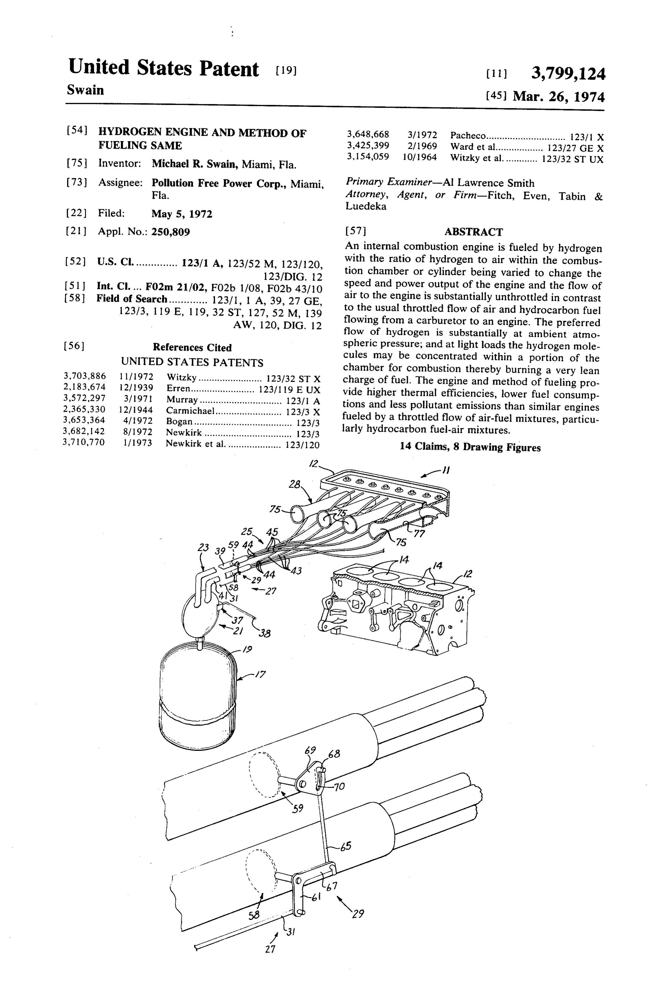
(21) Appl. No.: 250,809 57 ABSTRACT An internal combustion engine is fueled by hydrogen 52 U.S. C. .............. 123/1 A, 123/52 M, 123/120, with the ratio of hydrogen to air within the combus 123/DIG. 12 tion chamber or cylinder being varied to change the 5 Int. Cl. ... F02m 21/02, FO2b 1/08, FO2b 43/10 speed and power output of the engine and the flow of 58 Field of Search............. 123/1, 1 A, 39, 27 GE, air to the engine is substantially unthrottled in contrast 123/3, 119 E, 119, 32 ST, 127, 52 M, 139 to the usual throttled flow of air and hydrocarbon fuel AW, 120, DIG. 12 flowing from a carburetor to an engine. The preferred flow of hydrogen is substantially at ambient atmo 56) References Cited spheric pressure; and at light loads the hydrogen mole UNITED STATES PATENTS cules may be concentrated within a portion of the 3,703,886 1 1/1972 Witzky........................ 123/32 ST X chamber for combustion thereby burning a very lean 2, 183674 12/1939 Erren........................ 12311 19 EUX charge of fuel. The engine and method of fueling pro 3,572,297 3/197l Murray............................... 123/1 A vide higher thermal efficiencies, lower fuel consump 2,365,330 1 2/1944 Carmichael......................... 123/3 X tions and less pollutant emissions than similar engines 3,653,364 4/1972 Bogan..................................... 123/3 fueled by a throttled flow of air-fuel mixtures, particu 3,682, 142 8/1972 Newkirk................................. 123/3 larly hydrocarbon fuel-air mixtures. 3,710,770 1 / 1973 Newkirk et al..................... 123/120 14 Claims, 8 Drawing Figures
Page 2
Drawing sheet — no readable text.
Page 3
Drawing sheet — no readable text.
Page 4
Drawing sheet — no readable text.
Page 5
Drawing sheet — no readable text.
Page 6
HYDROGEN ENGINE AND METHOD OF FUELING closed herein will be described in connection with vehi SAME cles but the engine amd method of the invention may be used for purposes other than powering a vehicle.
This invention relates generally to internal combus In contrast to gasoline and other hydrocarbon fueled tion engines and more particularly to an internal com 5 internal combustion engines hydrogen fueled engines bustion engine fueled by hydrogen and to a method of will emit fewer pollutants with the substantial elimina fueling an internal combustion engine with a fuel mix tion of carbon monoxide and hydrocarbons; and with ture of hydrogen and air. the efficiencies achieved with the new method of fuel The reduction of air pollutants from internal combus ing the engine be more thermally efficient than a com tion engines has been the subject of considerable study O parable gasoline fueled engine thereby resulting in and investigation. Virtually all of the internal combus fewer total polluting emissions per vehicle mile. tion engines in present use in automobiles employ a hy In contrast to a gasoline fueled internal combusion drocarbon, fossil fuel which exhausts hydrocarbons, ni engine, water vapor, free N, and free O, are the princi tric oxides, carbon dioxide and carbon monoxide. Be pal constituents of the exhaust of the hydrogen fueled cause of the extent of pollution in the atmosphere from 5 engine except, of course, when other fluids or gases are current engines, the U.S. Government has set new present as may result as a by-product of an on vehicle emission standards for automotive vehicle engines hydrogen generator or may be used for other purposes which require a considerable reduction in pollutants such as lowering nitric oxide emissions. over the next several years. In accordance with a general object of the present in Gasoline, in addition to being a source of numerous 20 vention, a new and improved hydrogen fueled internal and substantial quantities of air pollutants from the ex combustion engine and method of fueling the same are haust of an automotive engine, requires an extensive provided.
carburetor system and a complex manifolding system These and other objects of the invention will become to atomize the gasoline and distribute properly the at apparent from the following detailed description taken omized gasoline-air fuel mixture to each cylinder of the 25 in connection with the accompanying drawings in engine for various operating conditions including which:
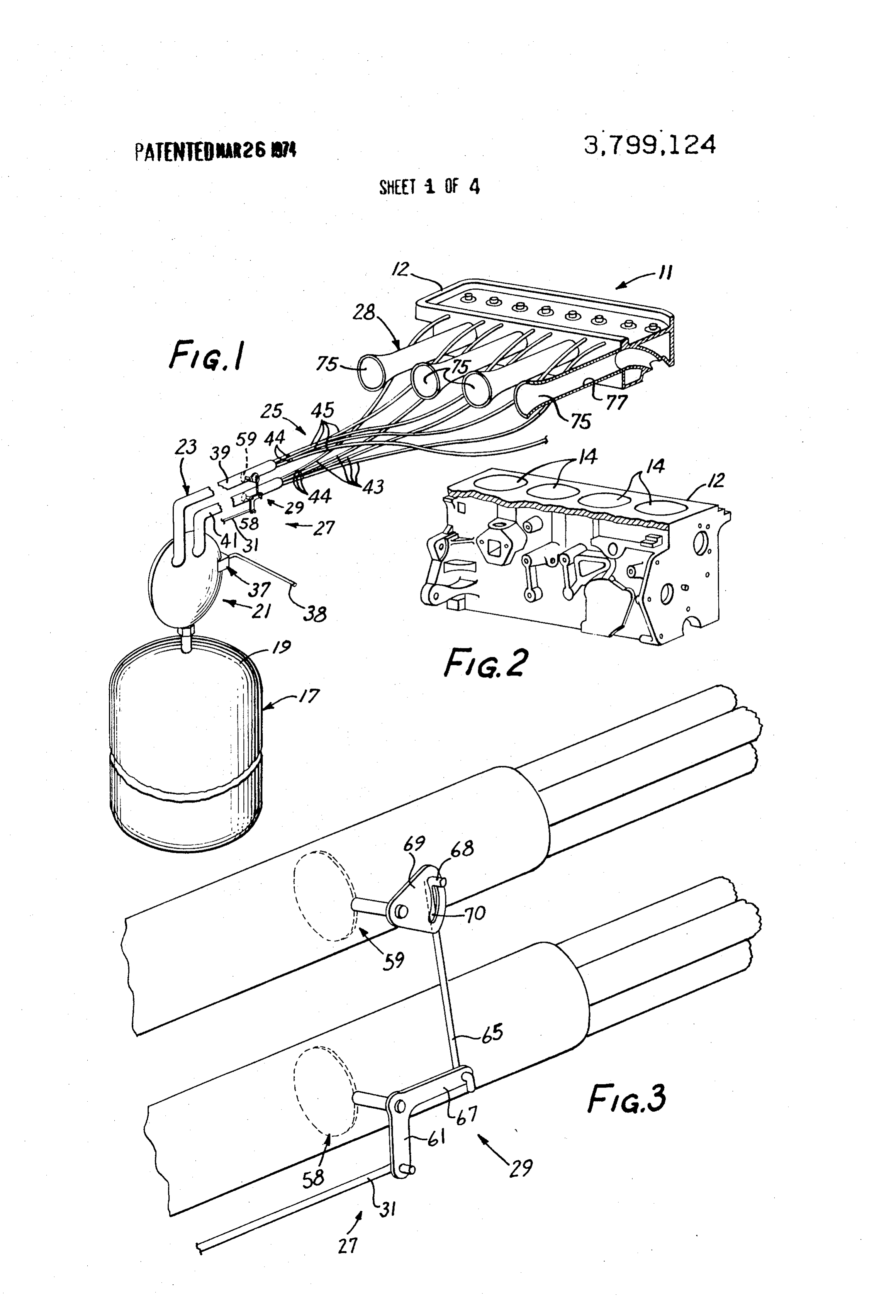
changes in demand for horsepower and speed without FIG. 1 is a fragmentary, illustrative view of a fueling encountering preignition or backfiring problems. To system and engine embodying the present invention; control the speed and power, the gasoline-air fuel mix FIG. 2 is a perspective view of an engine cylinder ture is throttled extensively at the carburetor resulting 30 block used for the invention illustrated in FIG. ; in inefficiencies termed pumping losses herein. The tor FIG. 3 is an enlarged diagrammatic view of a control tuous manifold passages from the carburetor to the en means used to regulate the flow of hydrogen to the en gine cylinders result in volumetric inefficiencies and gine shown in FIG. 1;
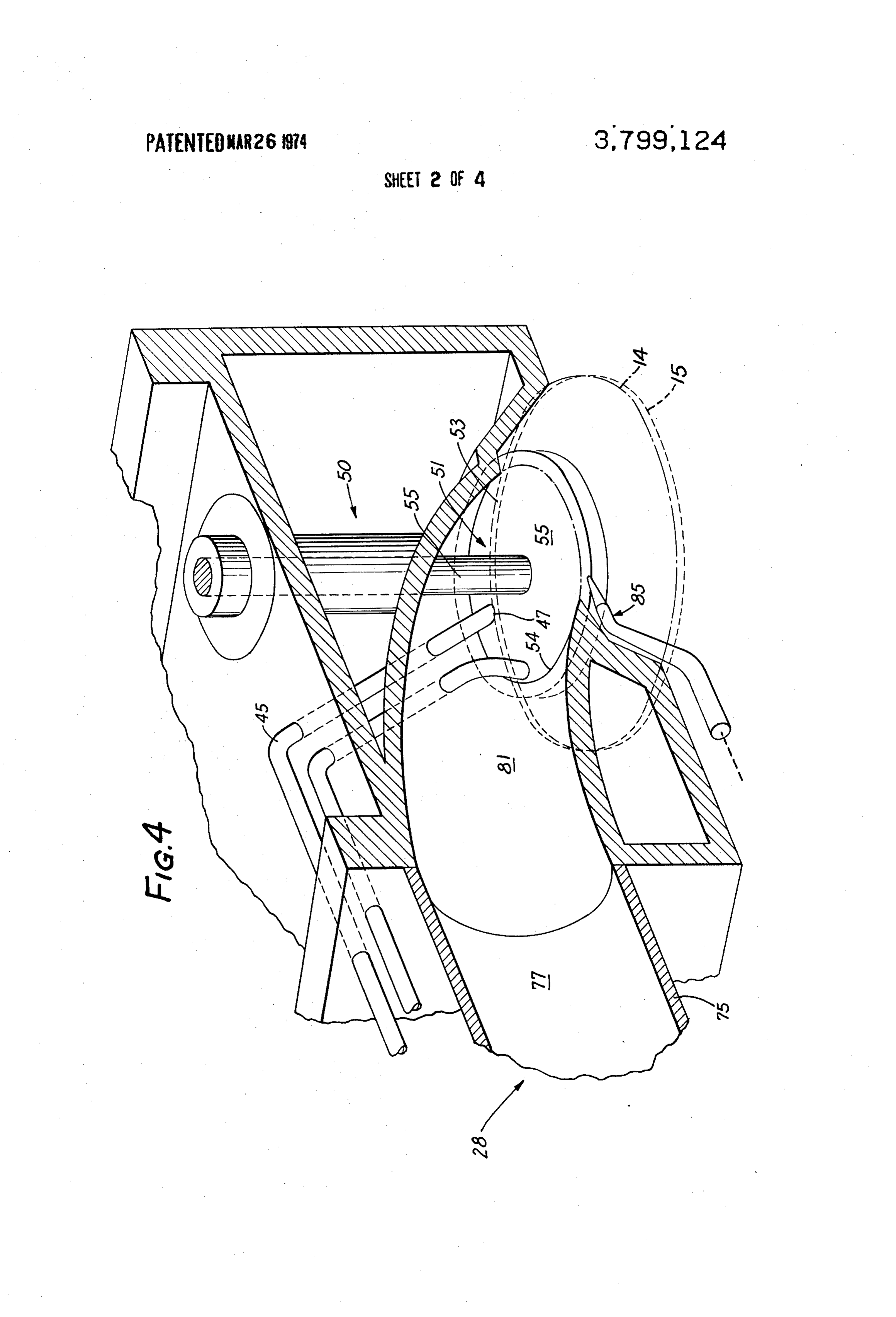
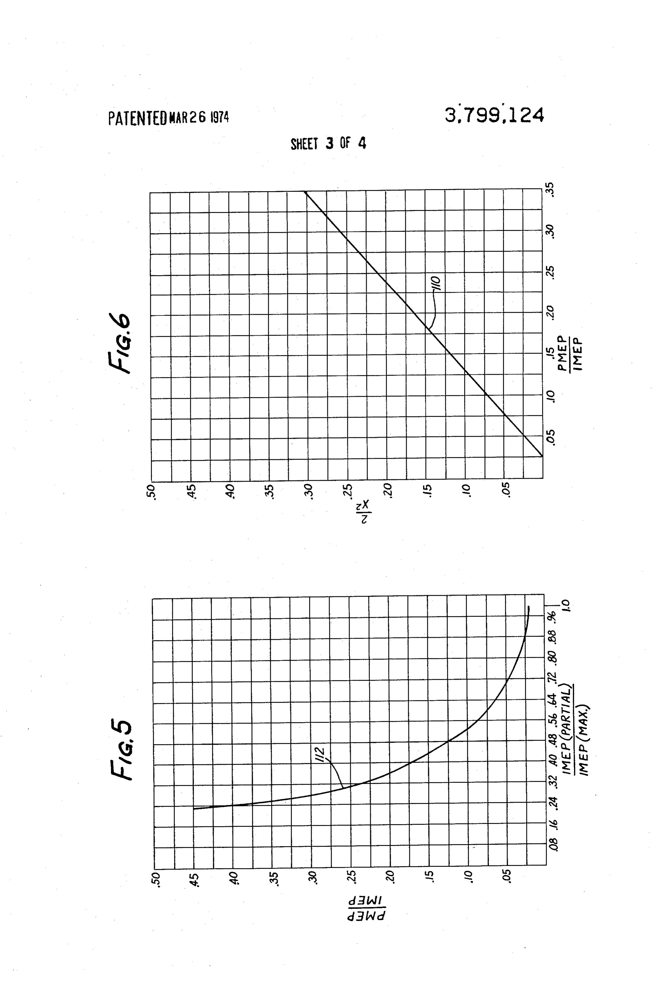
these pumping losses coupled with the pumping losses FIG. 4 is an enlarged view of an intake port to a com due to throttling decrease the efficiencies of gasoline 35 bustion chamber and of separate passageways for air fueled automotive engines. and hydrogen used in the engine shown in FIG. 1; Although electric battery driven and various other FIGS. 5, 6 and 7 are curves to illustrate engine per engines have been suggested for powering automotive formance; and vehicles, the gasoline internal combustion engine has 40 FIG. 8 illustrates an indicator card for an engine. retained widespread usage in automobiles because of As shown in the drawings for purposes of illustration, its ability to operate over a wide range of power de the invention is embodied in an internal combustion mands and speeds, its quick response to demand for engine 11 having a cylinder block 12 with a plurality of changes in power or in speed and because of its ability cylinders 14 therein. In a four-stroke cycle manner of to be relatively inexpensively manufactured. Also, in operation pistons 15 (FIG. 4) in each cylinder 14 are addition to performance characteristics, the current 45 reciprocated through an intake stroke, a compression gasoline engines have proven reliability coupled with a stroke, a power stroke and an exhaust stroke. The en reasonable cost of operation. In short, current internal gine 11 and its components, as best seen in FIGS. 1,2 combustion engines used in automobiles will idle at and 4 may be of conventional design in common use in light or no loads, will respond quickly to increases in automobiles except as otherwise described herein; but demand for power, will accelerate a vehicle rapidly, 50 the engine is fueled with hydrogen and is modified in will operate at light loads while cruising at high speeds a novel manner to operate, preferably without the use and will run for substantially long periods of operation of carburetor in this illustrated and preferred embodi without having to stop for refueling. Regardless of what ment of the invention. The engine 11 may have its cyl is done to develop substitutes for the internal combus 55 inders arranged in a conventional and standard V form tion engine it is expected that at least 100 million more rather than in the straight vertical in line form shown such engines will be built over the next 10 years, and in FIG. 2. Manifestly, the number of the cylinders, the the air we breath 10 years from now will depend to a bore size thereof, the valving arrangement, the stroke large extent on how these engines are built and fueled. of the pistons, connecting rod length or camshaft de 60 sign may be varied considerably from that described
The present invention is particularly directed to using herein while employing the principles of the invention. the internal combustion engine because of its reliability The use of hydrogen as a fuel for internal combustion and other proven qualities; and to adapting it to using engines has been investigated heretobefore by other re hydrogen as a fuel for the twin purposes of reducing ex searchers. More specifically, early investigations by haust emissions therefrom as contrasted with exhaust 65 these researchers indicated that hydrogen-fuel air mix emissions from gasoline fueled internal combustion en tures in internal combustion engines could produce gines and of providing a thermally more efficient en suitable power, but these research efforts found that gine. The hydrogen fueled engine and method dis with hydrogen as a fuel there existed a tendency for the
Page 7
engine to knock and for the fuel to preignite unless low In the preferred fueling system, hydrogen is stored in compression ratios and lean mixtures were used. Later a supply means 17, in this instance in the form of a experiments of others indicated that the knock and pre metal cylinder 19 holding a compressed gaseous form ignition with a hydrogen-fuel mixture could be over of hydrogen at a pressure substantially higher than am come at higher compression ratios provided that the bient atmospheric pressure. Hydrogen from the supply combustion chambers were free of fluffy carbon depos means 17 flows through a pressure regulator means 21 its, the exhaust valve temperatures kept low, and low in which the pressure of the hydrogen is reduced sub operating temperature spark plugs were used. How stantially from the pressure at which the hydrogen is ever, the thermal efficiency results obtained by these stored in the supply tank 9. In this instance, the pres other researchers when operating similar engines under 10 sure regulator means 2 reduces the pressure of hydro similar operating conditions with gasoline or with hy gen to the ambient atmosphere or slightly thereabove drogen were not significantly different. While hydro for flow through a conduit means 23 to an intake con gen-fueled, internal combustion engines have been in duit means 25 leading to the cylinders 14. vestigated before; they have not been heretofore fueled In accordance with another important aspect of the and modified to achieve the efficiency as now obtained 15 invention, the engine 11 may be fueled with an induc with the present invention. tion technique without the use of a carburetor or with In accordance with the preferred embodiment of the out an expensive fuel injector system for spraying fuel invention, very substantial improvements in thermal into a combustion chamber while the air is compressed efficiency for an internal combustion engine are ob therein. As will be explained in greater detail, hydrogen tained with the use of a hydrogen fuel mixture rather 20 at substantially atmospheric pressure may be inducted than a hydrocarbon fuel such as gasoline and very in into the cylinders 14 during the intake stroke of the pis proved emission results are obtained over the emissions tons 15 therein; and an unthrottled flow of air may be obtained with gasoline fueled engines. The improved provided through an air inlet means 28 into the cylin thermal efficiencies may be obtained by a fueling ders 14 during the intake strokes. By allowing unthrot method which eliminates the carburetor and pumping 25 tled flow of air into the cylinders 14, the substantially losses associated there with and by the use of very lean low subatmospheric pressures experienced with carbu fuel-air ratios particularly when the engine is idling or retor fueled and throttled gasoline engines may be sub at very light operating loads. In the preferred method stantially eliminated. This relatively high vacuum on of fueling, the ratio of hydrogen to air within the com 30 the combustion side of the pistons facilitates oil flow bustion chamber is varied to change the speed and past the piston rings and the mixture of oil with the fuel power output of the engine in contrast to the usual thereby adding to the polluting emissions of a gasoline throttling of the flow of the gasoline air mixture to engine, particularly as the engine becomes older and change speed and power in the conventional gasoline the piston rings become worn.
engine. As will be explained in greater detail, advan 35 With a free flow of air into the cylinders 14 during tage is taken of hydrogen's flame speed being faster the intake stroke, the leaness or richness of the fuel than the flame speed of gasoline and hydrogen's wider mixture is controlled by a control means 27 for meter range of ignition to allow the use of lean hydrogen to ing the flow of hydrogen to the cylinders 14 in response air ratios and to vary directly the flow of hydrogen into to movement of an actuator 31 which may be operated the combustion chambers to vary the engine's power 40 by an accelerator pedal (not shown) as in an automo and speed output. Also, as will be explained in greater tive vehicle. The illustrated control means 27 is in the detail, by admitting substantially unthrottled air flow form of a valve means 29 which meters the flow of hy into the cylinders 14 and by eliminating the tortuous drogen to the cylinder intake conduit means 25. As will manifolds and throttle plates of a carburetor, the be explained, when the engine is idling the valve means pumping losses of the gasoline engine may be substan 45 permits a predetermined, low flow rate of hydrogen tially reduced. through the conduit means 25; whereas with increased More specifically and in accordance with an impor demand as by an operation of the actuator 31, the valve tant aspect of the invention, the engine 11 may be fu means will open further and permits a larger flow rate eled at lighter loads in a manner to concentrate the of hydrogen through the intake conduit means 25 and lightweight molecules of hydrogen within a portion of into the cylinders to increase the percentage of fuel in each combustion chamber 14 to the extent that the SO the cylinders 14. As the air intake means 28 is open and ratio of hydrogen to air in each chamber may be actu unthrottled, the percent of air in the cylinders varies ally less than that necessary for supporting combustion inversely and proportionally to the percentage of hy considering the volume of the combustion chamber as drogen fuel being admitted into the cylinders. An addi a whole. For example, it has been possible to convert 55 tional advantage of this method is that the intake mani a standard gasoline engine to use hydrogen gas and to folding does not contain explosive mixtures of hydro swirl the gas in the center of the combustion chamber gen and oxidant; this minimizes the hazards associated to achieve a very lean below 4.1 percent (by volume) with backfiring.
of hydrogen to air in the fuel mixture being burnt; Referring now in greater detail to the illustrated hy whereas, if the hydrogen were homogenuously dis 60 drogen engine 11 and to the preferred manner of fuel persed within the entire volume of the combustion ing the same, the engine 11 is modified to advanta chamber, the percentage of hydrogen to air would have geously capitalize on the attributes of hydrogen, partic to be about at least 4.1 percent. Thus, at no or low ularly as contrasted with gasoline as a fuel for an inter loads, it is possible to stratify or concentrate the light nal combustion engine.
weight molecules of hydrogen to burn a very lean 65 More specifically, hydrogen has a flame speed faster charge which results in a high thermal efficiency for the than gasoline and has a good flame speed over a range engine, lower fuel consumptions, and less pollutant of fuel air ratios larger than gasoline-air fuel ratios. As emissions. used herein the term hydrogen refers to a gas or gas
Page 8
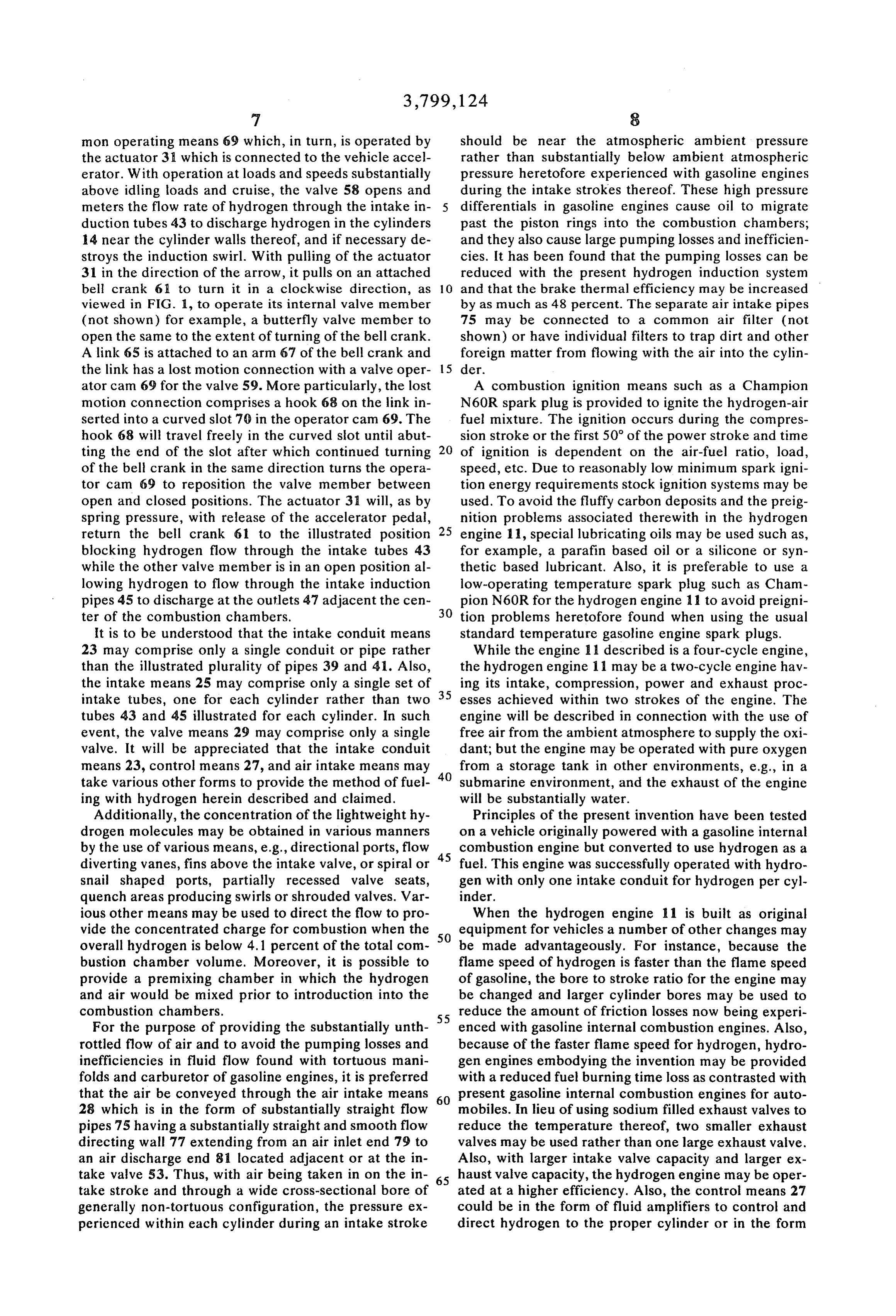
S 6 mixture which is largely dependent on the formation of about the speed of sound through the conduit means 23 oxygen-hydrogen bonds for the production at available which is very high in hydrogen gas, to the valve means energy to do work. This gas then may contain percent 29 and if the latter is open, an increased pressure ages of other gases which are either the by-products of through the intake conduit means 25 results in an in an on board hydrogen generation source, constituents 5 creased flow rate of hydrogen to the cylinders 14 than added to reduce nitorgen oxides emissions or increase would be realized had the pressure remained substan octane number. One of the shortcomings of gasoline is tially constant. Thus, by the combination of the meter that it will not support a sufficiently fast flame speed for ing of the valve opening and the pressure of the gas use in internal combustion engines over very low gaso flowing through the intake conduit means 25 the hy line-air ratios as will hydrogen. Additionally, hydrogen 10 drogen engine can be made particularly responsive to has a faster flame speed and burns over a wider range demands for increased speed or load. of fuel-air ratios, e.g., about 4.1 percent to 74 percent The illustrated conduit 23 is in the form of a primary hydrogen to air by volume, than hydrocarbon fuels hydrogen flow conduit or pipe 41 and a secondary hy such as methane, ethane, ethylene and acetylene. This drogen flow conduit or pipe 39 each which extends flame speed characteristic of hydrogen at the lean side 15 from the outlet of the pressure regulating means 21 to of air-fuel ratios is advantageously used herein, e.g., for the control valve means 29. The fuel supply means 17 a 1971 Toyota 1600 an 8 percent hydrogen-air fuel may be at a remote location as is the usual gasoline sup ratio is used at cruising speed for an automotive vehicle ply tank. In this instance, hydrogen flows through the and below 4.1 percent hydrogen to air fuel ratio may pipe 41 during heavy power or speed demands and hy be used for idling. With the engine 11 illustrated, the 20 drogen flows through the pipe 39 only at light loads. maximum fuel ratio of hydrogen-air is about 31.3 per The illustrated intake conduit means 25 has an assem cent hydrogen for maximum power. bly of primary induction tubes 43 connected in fluid Although the hydrogen is illustrated as being stored communication with the primary pipe 41 and extending in a compressed gaseous state in a cylinder 19, the in to each cylinder 14. Likewise, an assembly of secon duction system of the present invention is particularly 25 dary induction tubes 45 are each connected to one of adaptable for use with hydrogen generated at low or the combustion chambers 4 to admit hydrogen to near ambient atmospheric pressure. Hence, this inven each chamber with proper operation of the control tion may be used to eliminate the drawbacks of a need valve means 27. The secondary induction tubes 45 are, for high pressure fuel tanks and fuel supply stations 30 as best seen in FIG. 2, provided with outlets 47 which therefor. For instance, hydrogen may be stored at low discharge generally at the center of each cylinder 14 pressure by a hydride, such as magnesium-nickel or and in a manner to swirl the hydrogen to form the strat magnesium-copper hydride, from which it is thought ified concentrated charge at the center of the chamber. that hydrogen may be recovered economically, safely On the other hand, for the heavier power and speed de and in sufficient quantities to provide a long-range fuel 35 mands, the primary induction tubes 43 deliver to the supply comparable to the range achieved with present sides of the combustion chambers a richer mixture of day gasoline storage tanks on automobile engines. Of hydrogen in excess of the 4.1 percent hydrogen to air. course, liquid hydrogen could be stored and evapo The flow and distribution of hydrogen to each of the rated to supply the hydrogen introduced into the com cylinders may be regulated by a flow control means to bustion chambers. In addition, a number of chemical 40 compensate for different path lengths and curves in the reactions release hydrogen (oxidation of ferrous met intake tubes. The flow control means may take various als, aluminum, calcium hydride, etc.) which may pro forms such as an adjustment screw 44 projecting into vide a suitable source for fueling a hydrogen powered each tube 43 and 45 for turning to open or restrict gas vehicle. In addition, hydrogen can be generated on the flow therethrough.
vehicle by the reaction of water and a hydrocarbon fuel The particular shape, number and operation of an in such as gasoline, kerosene, etc., the resulting fuel being take valve means 51 may be varied considerably for a a mixture of mainly hydrogen gas and carbon dioxide. number of considerations such as efficiencies of flow, The gaseous by-products from the hydrogen gas gener ease of manufacturing, etc. For purposes of illustration ating process may also be passed through the engine only, the intake valve means 50 comprises a single before being exhausted. valve means 50 comprising a single valve member 53 The operator of the hydrogen engine 11 may be pro- 50 for each cylinder 14 movable by a suitable actuator 55 vided with means for providing responsiveness of the between a lowered open position in which hydrogen hydrogen engine to demands for increased speed or and air may flow through an intake port 54 into the cyl power by providing the control means 27 with a flow inder 14 and an upper closed position in which a back rate increase means 37 which, in this instance, in or upper surface 55 of the valve member 53 abuts and creases the flow rate by increasing the pressure of gase 55 covers the outlets of the hydrogen intake tubes 43 and ous hydrogen in the conduit means 23 and conse 45. With closure of the valve member 53, the intake quently an increase in flow rate of hydrogen past the port is also closed to the air intake means 28. valve means 29 and into the cylinder 14. For instance, When using two separate sets of intake tubes 43 and the flow rate means 37 may be operated in response to 60 45 and only a single intake valve member 53 for each a manual movement of the vehicle operator such as cylinder 14, the valve means 29 controls which set of through an actuator 38 in the form of a control rod the intake tubes 43 and 45 will be open to hydrogen connected to the pressure regulating means 21 to reset flow therethrough. The valve means 29 accomplishes the level of its output pressure to a higher level this flow control by having a primary valve 58 and a whereby an output of hydrogen gas at a higher pressure 65 secondary valve 59 each controlling flow through its than the normal pressure is obtained across the pres respective primary and secondary pipes 39 and 41 to sure regulating means 21. The increase in hydrogen the respective manifold sets of intake tubes 43 and 45. pressure is transmitted almost instantaneously, i.e., at preferably, the valves 58 and 59 are operated by a com
Page 9
mon operating means 69 which, in turn, is operated by should be near the atmospheric ambient pressure the actuator 3 which is connected to the vehicle accel rather than substantially below ambient atmospheric erator. With operation at loads and speeds substantially pressure heretofore experienced with gasoline engines above idling loads and cruise, the valve 58 opens and during the intake strokes thereof. These high pressure meters the flow rate of hydrogen through the intake in differentials in gasoline engines cause oil to migrate duction tubes 43 to discharge hydrogen in the cylinders past the piston rings into the combustion chambers; 14 near the cylinder walls thereof, and if necessary de and they also cause large pumping losses and inefficien stroys the induction swirl. With pulling of the actuator cies. It has been found that the pumping losses can be 31 in the direction of the arrow, it pulls on an attached reduced with the present hydrogen induction system bel crank 6 to turn it in a clockwise direction, as 10 and that the brake thermal efficiency may be increased viewed in FIG. 1, to operate its internal valve member by as much as 48 percent. The separate air intake pipes (not shown) for example, a butterfly valve member to 75 may be connected to a common air filter (not open the same to the extent of turning of the bell crank. shown) or have individual filters to trap dirt and other A link 65 is attached to an arm 67 of the bell crank and foreign matter from flowing with the air into the cylin the link has a lost motion connection with a valve oper 15 der.
ator cam 69 for the valve 59. More particularly, the lost A combustion ignition means such as a Champion motion connection comprises a hook 68 on the link in N60R spark plug is provided to ignite the hydrogen-air serted into a curved slot 70 in the operator cam 69. The fuel mixture. The ignition occurs during the compres hook 68 will travel freely in the curved slot until abut sion stroke or the first 50 of the power stroke and time ting the end of the slot after which continued turning 20 of ignition is dependent on the air-fuel ratio, load, of the bell crank in the same direction turns the opera speed, etc. Due to reasonably low minimum spark igni tor cam 69 to reposition the valve member between tion energy requirements stock ignition systems may be open and closed positions. The actuator 31 will, as by used. To avoid the fluffy carbon deposits and the preig spring pressure, with release of the accelerator pedal, nition problems associated therewith in the hydrogen return the bell crank 61 to the illustrated position 25 engine 11, special lubricating oils may be used such as, blocking hydrogen flow through the intake tubes 43 for example, a parafin based oil or a silicone or syn while the other valve member is in an open position al thetic based lubricant. Also, it is preferable to use a lowing hydrogen to flow through the intake induction low-operating temperature spark plug such as Cham pipes 45 to discharge at the outlets 47 adjacent the cen pion N60R for the hydrogen engine 11 to avoid preigni ter of the combustion chambers. 30 tion problems heretofore found when using the usual It is to be understood that the intake conduit means standard temperature gasoline engine spark plugs. 23 may comprise only a single conduit or pipe rather While the engine described is a four-cycle engine, than the illustrated plurality of pipes 39 and 41. Also, the hydrogen engine 11 may be a two-cycle engine hav the intake means 25 may comprise only a single set of 35 ing its intake, compression, power and exhaust proc intake tubes, one for each cylinder rather than two esses achieved within two strokes of the engine. The tubes 43 and 45 illustrated for each cylinder. In such engine will be described in connection with the use of event, the valve means 29 may comprise only a single free air from the ambient atmosphere to supply the oxi valve. It will be appreciated that the intake conduit dant; but the engine may be operated with pure oxygen means 23, control means 27, and air intake means may 40 from a storage tank in other environments, e.g., in a take various other forms to provide the method of fuel submarine environment, and the exhaust of the engine ing with hydrogen herein described and claimed. will be substantially water. Additionally, the concentration of the lightweight hy Principles of the present invention have been tested drogen molecules may be obtained in various manners on a vehicle originally powered with a gasoline internal by the use of various means, e.g., directional ports, flow combustion engine but converted to use hydrogen as a diverting vanes, fins above the intake valve, or spiral or 45 fuel. This engine was successfully operated with hydro snail shaped ports, partially recessed valve seats, gen with only one intake conduit for hydrogen per cyl quench areas producing swirls or shrouded valves. Var inder.
ious other means may be used to direct the flow to pro When the hydrogen engine 11 is built as original vide the concentrated charge for combustion when the 50 equipment for vehicles a number of other changes may overall hydrogen is below 4.1 percent of the total com be made advantageously. For instance, because the bustion chamber volume. Moreover, it is possible to flame speed of hydrogen is faster than the flame speed provide a premixing chamber in which the hydrogen of gasoline, the bore to stroke ratio for the engine may and air would be mixed prior to introduction into the be changed and larger cylinder bores may be used to combustion chambers. reduce the amount of friction losses now being experi For the purpose of providing the substantially unth 55 enced with gasoline internal combustion engines. Also, rottled flow of air and to avoid the pumping losses and because of the faster flame speed for hydrogen, hydro inefficiencies in fluid flow found with tortuous mani gen engines embodying the invention may be provided folds and carburetor of gasoline engines, it is preferred with a reduced fuel burning time loss as contrasted with that the air be conveyed through the air intake means 60 present gasoline internal combustion engines for auto 28 which is in the form of substantially straight flow mobiles. In lieu of using sodium filled exhaust valves to pipes 75 having a substantially straight and smooth flow reduce the temperature thereof, two smaller exhaust directing wall 77 extending from an air inlet end 79 to valves may be used rather than one large exhaust valve. an air discharge end 81 located adjacent or at the in Also, with larger intake valve capacity and larger ex take valve 53. Thus, with air being taken in on the in 65 haust valve capacity, the hydrogen engine may be oper take stroke and through a wide cross-sectional bore of ated at a higher efficiency. Also, the control means 27 generally non-tortuous configuration, the pressure ex could be in the form of fluid amplifiers to control and perienced within each cylinder during an intake stroke direct hydrogen to the proper cylinder or in the form
Page 10
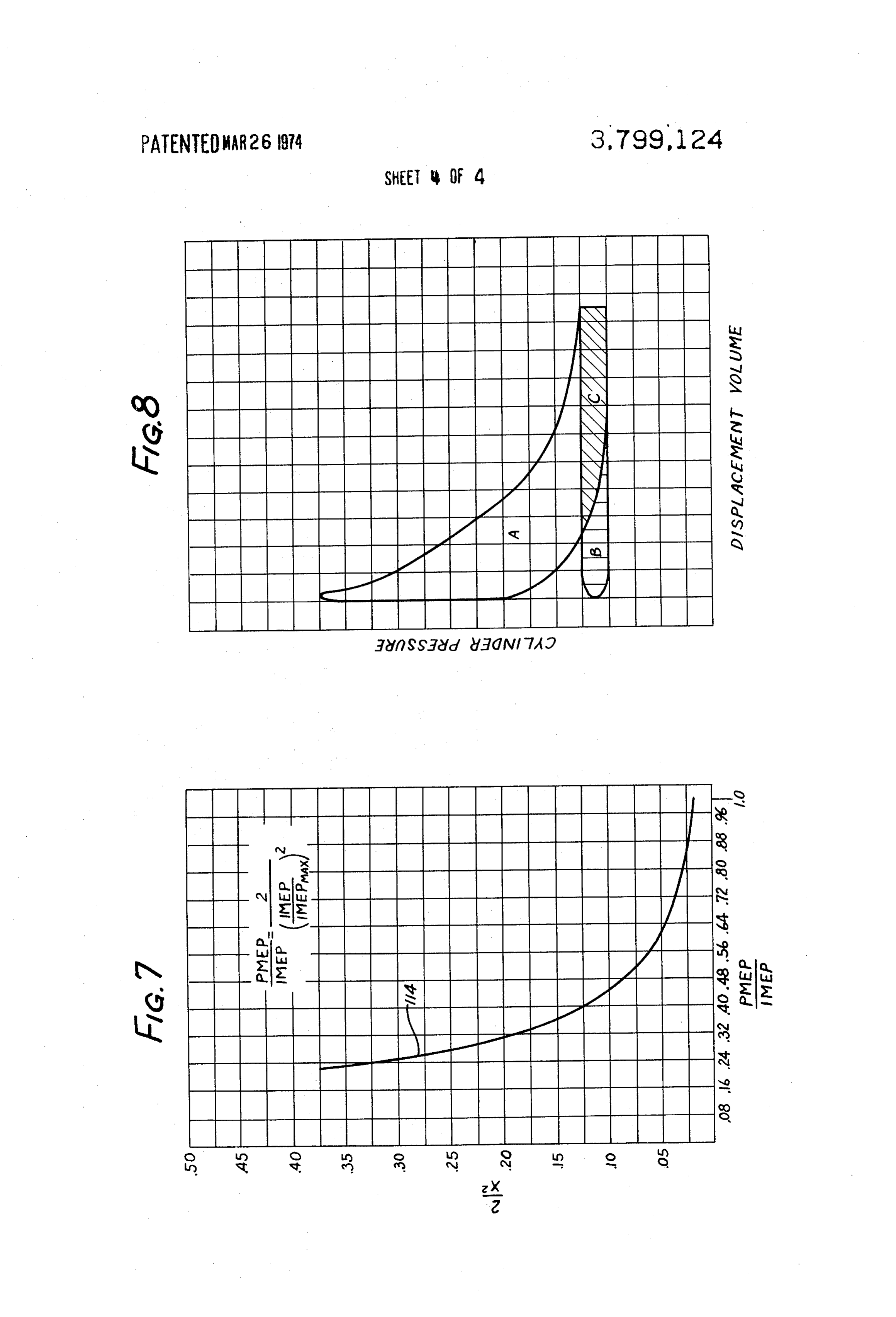
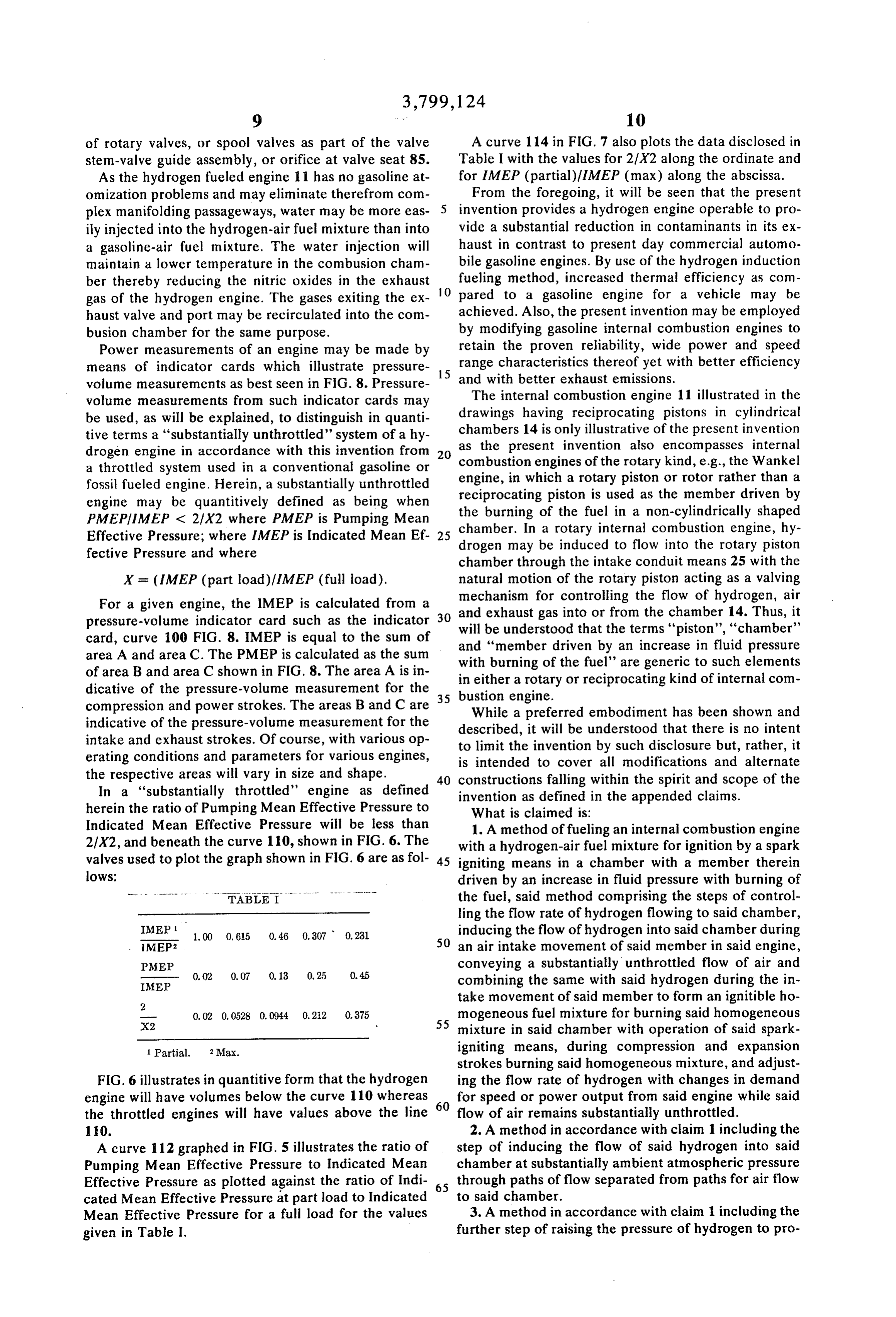
of rotary valves, or spool valves as part of the valve A curve 114 in FIG. 7 also plots the data disclosed in stem-valve guide assembly, or orifice at valve seat 85. Table I with the values for 2/X2 along the ordinate and As the hydrogen fueled engine 11 has no gasoline at for IMEP (partial)/IMEP (max) along the abscissa. omization problems and may eliminate therefrom com From the foregoing, it will be seen that the present plex manifolding passageways, water may be more eas- 5 invention provides a hydrogen engine operable to pro ily injected into the hydrogen-air fuel mixture than into vide a substantial reduction in contaminants in its ex a gasoline-air fuel mixture. The water injection will haust in contrast to present day commercial automo maintain a lower temperature in the combusion cham bile gasoline engines. By use of the hydrogen induction ber thereby reducing the nitric oxides in the exhaust fueling method, increased thermal efficiency as com gas of the hydrogen engine. The gases exiting the ex 10 pared to a gasoline engine for a vehicle may be haust valve and port may be recirculated into the com achieved. Also, the present invention may be employed busion chamber for the same purpose. by modifying gasoline internal combustion engines to Power measurements of an engine may be made by retain the proven reliability, wide power and speed means of indicator cards which illustrate pressure 15 and range characteristics thereof yet with better efficiency volume measurements as best seen in FIG. 8. Pressure with better exhaust emissions. volume measurements from such indicator cards may The internal combustion engine 11 illustrated in the be used, as will be explained, to distinguish in quanti drawings having reciprocating pistons in cylindrical tive terms a “substantially unthrottled' system of a hy chambers as the 14 is only illustrative of the present invention present invention also encompasses internal drogen engine in accordance with this invention from 20 a throttled system used in a conventional gasoline or engine,combustion engines of the rotary kind, e.g., the Wankel fossil fueled engine. Herein, a substantially unthrottled reciprocatingin which a rotary piston or rotor rather than a engine may be quantitively defined as being when the burning ofpiston the is used as the member driven by fuel in a non-cylindrically shaped
PMEP/IMEP < 2/X2 where PMEP is Pumping Mean chamber. In a rotary internal
Effective Pressure; where IMEP is Indicated Mean Ef- 25 drogen may be induced to flowcombustion engine, hy into the rotary piston fective Pressure and where chamber through the intake conduit means 25 with the
X = (IMEP (part load)/IMEP (full load). natural motion of the rotary piston acting as a valving For a given engine, the IMEP is calculated from a and exhaust for mechanism gas controlling the flow of hydrogen, air into or from the chamber 14. Thus, it pressure-volume indicator card such as the indicator 30 will be understood that the terms "piston', “chamber' card, curve 100 FIG. 8. IMEP is equal to the sum of and "member driven by an increase in fluid pressure area A and area C. The PMEP is calculated as the sum of area B and area C shown in FIG. 8. The area A is in with burning of the fuel' are generic to such elements in either dicative of the pressure-volume measurement for the 35 bustion engine. a rotary or reciprocating kind of internal com compression and power strokes. The areas B and C are While a preferred embodiment has been shown and indicative of the pressure-volume measurement for the described, it will be understood that there is no intent intake and exhaust strokes. Of course, with various op to limit the invention by such disclosure but, rather, it erating conditions and parameters for various engines, is intended to cover all modifications and alternate the respective areas will vary in size and shape. 40 constructions falling within the spirit and scope of the In a "substantially throttled' engine as defined invention as defined in the appended claims. herein the ratio of Pumping Mean Effective Pressure to What is claimed is:
Indicated Mean Effective Pressure will be less than 1. A method of fueling an internal combustion engine 2/X2, and beneath the curve 110, shown in FIG. 6. The with a hydrogen-air fuel mixture for ignition by a spark valves used to plot the graph shown in FIG. 6 are as fol 45 igniting means in a chamber with a member therein lows: driven by an increase in fluid pressure with burning of TABLE I the fuel, said method comprising the steps of control ling the flow rate of hydrogen flowing to said chamber,
IMEP 1 1.00 0, 615 0.46 0.307 0.231 inducing the flow of hydrogen into said chamber during MEP2 50 an air intake movement of said member in said engine, PMEP conveying a substantially unthrottled flow of air and 0,02 0.07 0, 13 0,25 0.45 combining the same with said hydrogen during the in
IMEP
take movement of said member to form an ignitible ho -- 0.02 0, 0528 0.0944 0.22 0.375 mogeneous fuel mixture for burning said homogeneous X2 55 mixture in said chamber with operation of said spark 1 Partial. 2 Max. igniting means, during compression and expansion strokes burning said homogeneous mixture, and adjust
FIG. 6 illustrates in quantitive form that the hydrogen ing the flow rate of hydrogen with changes in demand engine will have volumes below the curve 110 whereas 60 for speed or power output from said engine while said the throttled engines will have values above the line flow of air remains substantially unthrottled. 10. 2. A method in accordance with claim 1 including the A curve 112 graphed in FIG. 5 illustrates the ratio of step of inducing the flow of said hydrogen into said Pumping Mean Effective Pressure to Indicated Mean chamber at substantially ambient atmospheric pressure Effective Pressure as plotted against the ratio of Indi 65 through paths of flow separated from paths for air flow cated Mean Effective Pressure at part load to Indicated to said chamber.
Mean Effective Pressure for a full load for the values 3. A method in accordance with claim 1 including the given in Table I. further step of raising the pressure of hydrogen to pro
Page 11
vide an increase flow rate for said hydrogen in response 9. An internal combustion engine in accordance with to an increased demand for power of speed. claim 8 in which said pressure regulating means pro 4. A method in accordance with claim 1 including the vides hydrogen to said intake conduit means at a first further step of controlling the flow of hydrogen to each pressure substantially equal to ambient atmospheric chamber by opening and closing valves formed from pressure and in which said control means further com the motion of the valve train for said engine. prises means for providing an increase in pressure for 5. A method in accordance with claim 1 including the the hydrogen gas flowing through said intake conduit step of adding water, water vapor, or carbon dioxide to means to provide a fast response for a demand for an said hydrogen-fuel mixture to lower the temperature of increase in power or speed for said engine. the burning and thereby reduce the nitric oxide emis 10 10. An internal combustion engine in accordance sions from the engine exhaust. with claim 7 in which said intake conduit means com 6. A method in accordance with claim 1 including the prises hydrogen intake tubes projecting to said combus further step of generating a hydrogen containing gas tion chambers and air intake pipes extending to said and passing any gaseous by-products from said hydro combustion chambers, said hydrogen intake tubes and gen generating step including carbon dioxide gas 15 said air intake pipes being separate and discrete from through said hydrogen burning engine. each other.
7. An internal combustion engine for burning a hy 11. An internal combustion engine in accordance drogen air fuel mixture, said engine comprising in com with claim 10 in which said air intake pipes each have bination: a plurality of combustion chambers for re a substantially smooth continuous wall defining a pas ceiving a homogeneous mixture of air and hydrogen 20 sageway extending from adjacent said cylinders to an therein, a piston movable in each of said combustion open end thereby alleviating inefficiencies due to flow chambers during an intake of hydrogen-air, a compres about sharp corners.
sion of the hydrogen and air, a burning of the hydro 12. An internal combustion engine in accordance gen-air fuel mixture, and exhaust of the resultant prod with claim 7 in which said intake conduit means com ucts of burning, means for burning said air fuel mixture 25 prises a first set of intake tubes for conveying hydrogen in said combustion chamber during said compression for light power and speed demands to said combustion and expansion strokes, an intake conduit means ex chambers and a second set of intake tubes for convey tending to each of said combustion chambers and for ing hydrogen to said combustion chambers for heavier conducting the flow of said fuel mixture by induction power and speed demands.
on said intake strokes of said pistons, a supply means 30 13. An internal combustion engine in accordance containing hydrogen connected to said intake conduit with claim 7 in which said intake conduit means com means to supply hydrogen to said intake conduit prises a set of intake tubes for conveying hydrogen and means, and control means for selectively regulating the distribution adjusting means are provided for regulat flow of hydrogen from said supply means to said intake ing the flow and distribution of hydrogen through the conduit means to vary the speed and power output of 35 respective ones of said tubes.
said engine, said varying of said hydrogen flow by said 14. An internal combustion engine in accordance control means causing an inversely proportional with claim 7 including a valve train means operatively change in the percentage of air in said fuel mixture and associated with said combustion chambers, valves in resulting in a substantially constant volume charge to said valve train associated with each of said combustion said cylinders. 40 chambers to move between an open position allowing 8. An internal combustion engine in accordance with flow of hydrogen gas into its associated combustion claim 7 in which said hydrogen supply means stores hy chamber and a closed position preventing flow of hy drogen gas at a pressure above a predetermined level, drogen gas into its associated combustion chamber, and in which said control means includes a pressure and means in said valve train for opening and closing regulator for reducing the pressure of hydrogen from 45 said valves in timed relationship to each other. said supply means to said intake conduit means. x k 2 k sk
Provenance
- Collection
- Cited prior art
- Original PDF
- patentimages.storage.googleapis.com →
- Filed
- 1972-05-05
- Pages
- 11
- Method
- pdftotext (the PDF's own text layer) + pdftoppm 300dpi page scans
- Source
- Google Patents bibliographic record
- Granted
- 1974-03-26
- Inventors
- M Swain; POLLUTION FREE POWER CORP
- Transcribed from
- patentimages.storage.googleapis.com →