patent · US3854494
Safety valve
17 December 1974
Page 1 — bibliographic record
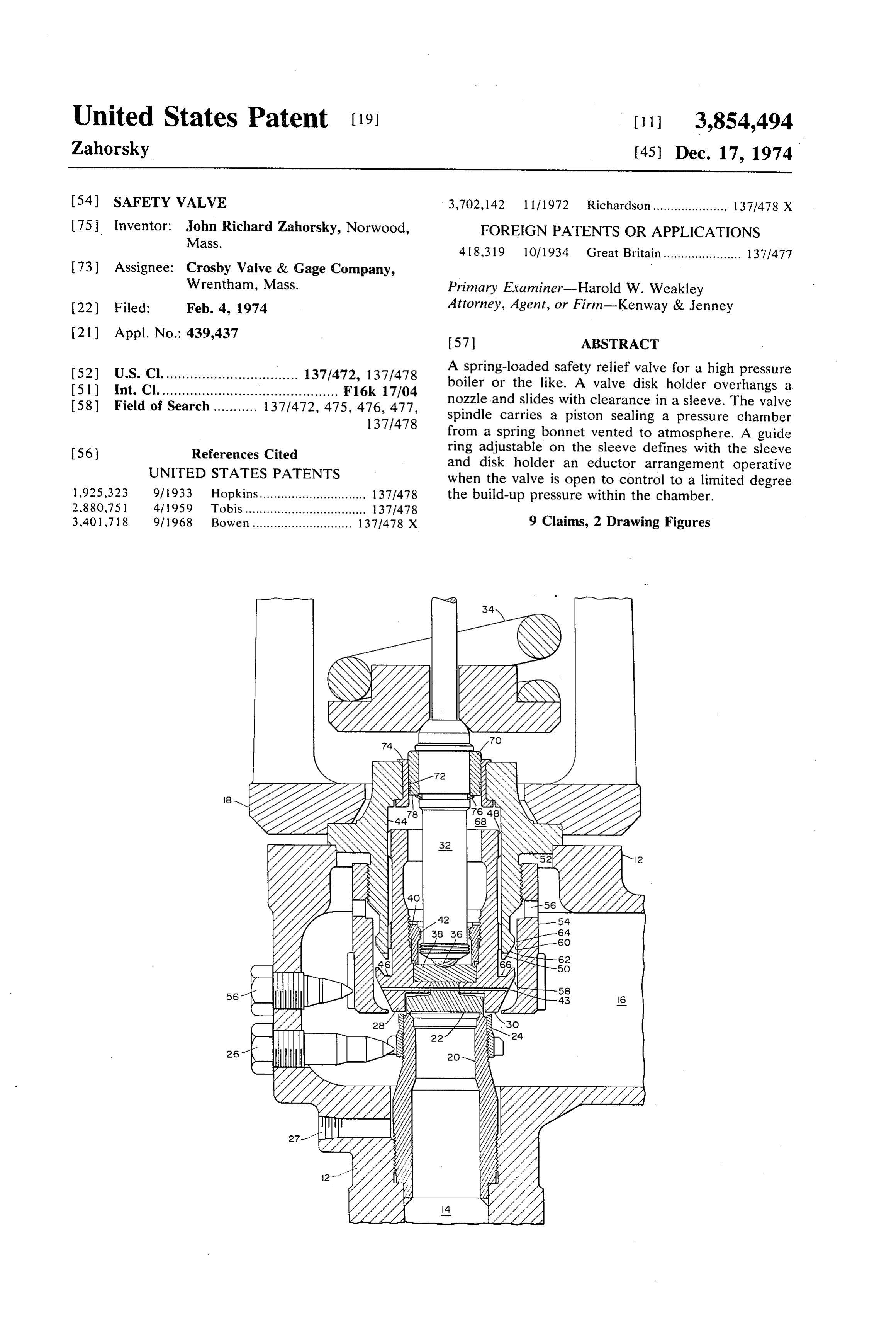
United States Patent (19) [11] 3,854,494 Zahorsky (45) Dec. 17, 1974 54 SAFETY VALVE 3,702,142 l l / 1972 Richardson..................... 137/478 X 75 Inventor: John Richard Zahorsky, Norwood, FOREIGN PATENTS OR APPLICATIONS Mass.
73) Assignee: Crosby Valve & Gage Company,
Wrentham, Mass. Primary Examiner-Harold W. Weakley (22 Filed: Feb. 4, 1974 Attorney, Agent, or Firm-Kenway & Jenney (21) Appl. No.: 439,437 57) ABSTRACT (52) U.S. Cl.................................. 137/472, 137/478 A spring-loaded safety relief valve for a high pressure (51 int. Cl. ............................................ F16k 17/04 boiler or the like. A valve disk holder overhangs a 58) Field of Search........... 137/472, 475, 476, 477, nozzle and slides with clearance in a sleeve. The valve 137/478 spindle carries a piston sealing a pressure chamber from a spring bonnet vented to atmosphere. A guide 56 References Cited ring adjustable on the sleeve defines with the sleeve
UNITED STATES PATENTS
and disk holder an eductor arrangement operative when the valve is open to control to a limited degree 1925,323 91933 Hopkins.............................. 1371.478 the build-up pressure within the chamber. 2,880,75l 4/1959 Tobis.................................. 371478 340 l 78 9/1968 Bowen ............................ 1371478 X 9 Claims, 2 Drawing Figures
Page 2
Drawing sheet — no readable text.
Page 3
Drawing sheet — no readable text.
Page 4
SAFETY WALWE then act on the valve face causing the valve to reopen. BACKGROUND OF THE INVENTION This results in a highly undesirable rapid cycle opera tion known as "chatter.'
This invention relates to safety valves, and more spe U.S. Pat. No. 2,880,751 issued Apr. 7, 1959 to R. A. cifically to spring loaded safety relief valves for high Tobis, et al, discloses another safety valve that utilizes pressure systems vented to atmosphere. a chamber above the valve piston to assist the valve In high pressure systems, such as steam boilers and closing. This valve, however, is designed to operate the like, it is necessary to have a safety relief valve that with a closed bonnet that does not vent to the atmo cracks open to release pressure at a set value, reaches sphere. When the valve is closed any superimposed a full open position quickly, and closes or reseats after O back pressure at the valve outlet communicates with the pressure falls to a safe level. Generally accepted cri the chamber, and acts to hold the valve closed and teria are that the valve should open fully when the sys therefore changes the set pressure. Thus, it is necessary tem or boiler pressure is within three percent above the that the superimposed back pressure be held to an ac set pressure and that it should reseat when the system ceptable level. The Tobis valve also has means to pressure is within four percent below the set pressure. 15 achieve reduction by build-up back pressure in the These characteristics are commonly termed a three chamber after opening, by placing an eductor sleeve in percent “full lift' and a four percent "blowdown.' the chamber, within the walls of the valve sleeve and It is well known in the art to achieve a 3 percent full disposed in the fluid stream between the fluid inlet to lift by utilizing a valve piston having a seating face that the chamber and the valve outlet passage. overhangs the seat or nozzle. A spring that urges the It is an object of this invention to provide a high pres valve to close is adjusted so that the valve cracks or be sure safety relief valve with a spring bonnet vented to gins to open at the set pressure, whereupon a "build atmosphere that achieves full lift at a minimal overpres up' pressure due to fluid flow in the valve outlet then sure and that also has an acceptably small blowdown. acts on the overhang area of the valve face in addition to the area defined by the seat. The resulting additional 25 Another object is to provide a safety valve that upward force quickly "pops' the valve to its full lift po achieves these operating conditions without damaging sition. This action is frequently aided by a nozzle ring the valve on closing, or causing chatter. and a guide ring, both adjustable, which are well Still another object is to provide a safety valve that known. In the full lift position the rate of flow of fluid 30 has a controlled, balanced operation. from the boiler or other vessel to the valve outlet is lim Yet another object is to provide a safety valve that is ited by the nozzle bore and the pressure is therefore re reliable, easily adjusted, and does not substantially in duced in a minimum time. As the pressure falls, the lift crease the cost of manufacture as compared to conven force acting on the full valve force is reduced until the tional safety valves.
spring force is dominant and the valve reseats suddenly. SUMMARY OF THE INVENTION Although conventional safety relief valves of the type A principal feature of the safety valve of this inven described operate effectively at low to medium pres tion is a venturi surface formed on the outer end por sures, serious obstacles arise when they are used in sys tion of the valve sleeve, coacting with an apertured tems operating at high pressures, for example pressures 40 guide ring to control the flow of effluent fluid to a in the range of 1,500 to 3,000 pounds per square inch chamber formed over the valve piston. The venturisur (psi). At these pressures it is extremely difficult to con face, in cooperation with the guide ring that forms an trol the lifting force, as balanced against the spring axially adjustable extension of the sleeve, forms a first force, so that the valve operates within a 3 percent full upwardly narrowing annular eductor passage that com lift and a four percent blowdown. These difficulties are 45 municates with an exit aperture port or ports formed in characterized by the fact that if the full lift criteria are the guide ring at a point or points above the venturi met, the blowdown pressure is more than four percent passage. A second upwardly narrowing annular passage below the set pressure. One solution is to use a heavier located directly below the first passage is formed by spring. It was found, however, that the extra spring and between the valve disk holder and the guide ring. force did not allow the valve to open fully within the Apertures machined in the lower end of the sleeve and desired overpressure. Other attempted solutions in 50 machined channels in the guiding diameter of the disk clude alterations in the shape of the valve, various com holder against the sleeve provide fluid communication binations of springs and dimensional changes in the from the valve face to the chamber, and the rate of valve, and the application of an auxiliary closing force. build-up of pressure in the chamber is thereby con An example of the latter method is disclosed in U.S. 55 trolled.
Pat. No. 3,401,718 issued Sept. 17, 1968 to W. H. A piston mounted on the valve stem is slidable in a Bowen, et al. The auxiliary force is generated by creat bushing in the upper portion of the sleeve and thereby ing a limited pressure chamber over the surface of the seals the chamber. The piston also provides a pressure valve piston opposite to the seat or nozzle. After the surface to balance some of the build-up pressure clos valve pops open, the chamber develops a back pressure 60 ing force on the side of the disk holder opposite to the limited by an overlap collar on the spindle which has nozzle, and therefore cushions the closing movement of lifted to vent the chamber, thus avoiding an excessively the valve. Another pressure chamber, also controlled sudden closing of the valve. This arrangement has dis by the annular passages, acts on an overhanging lip of advantages. When the valve recloses and the collar the valve piston located below the lower sleeve end. seals, the back pressure build up may become so sud 65 These and other features and objects of the invention den and large that the valve slams closed with sufficient will be more fully understood from the following de force to damage the valve piston or the seat. Further, tailed description which should be read in connection when the valve is seated, residual fluids in the chamber with the drawings.
Page 5
BRIEF DESCRIPTION OF THE DRAWINGS
surface 62, in cooperation with the passage 58, controls the flow of the effluent fluid through the apertures 50
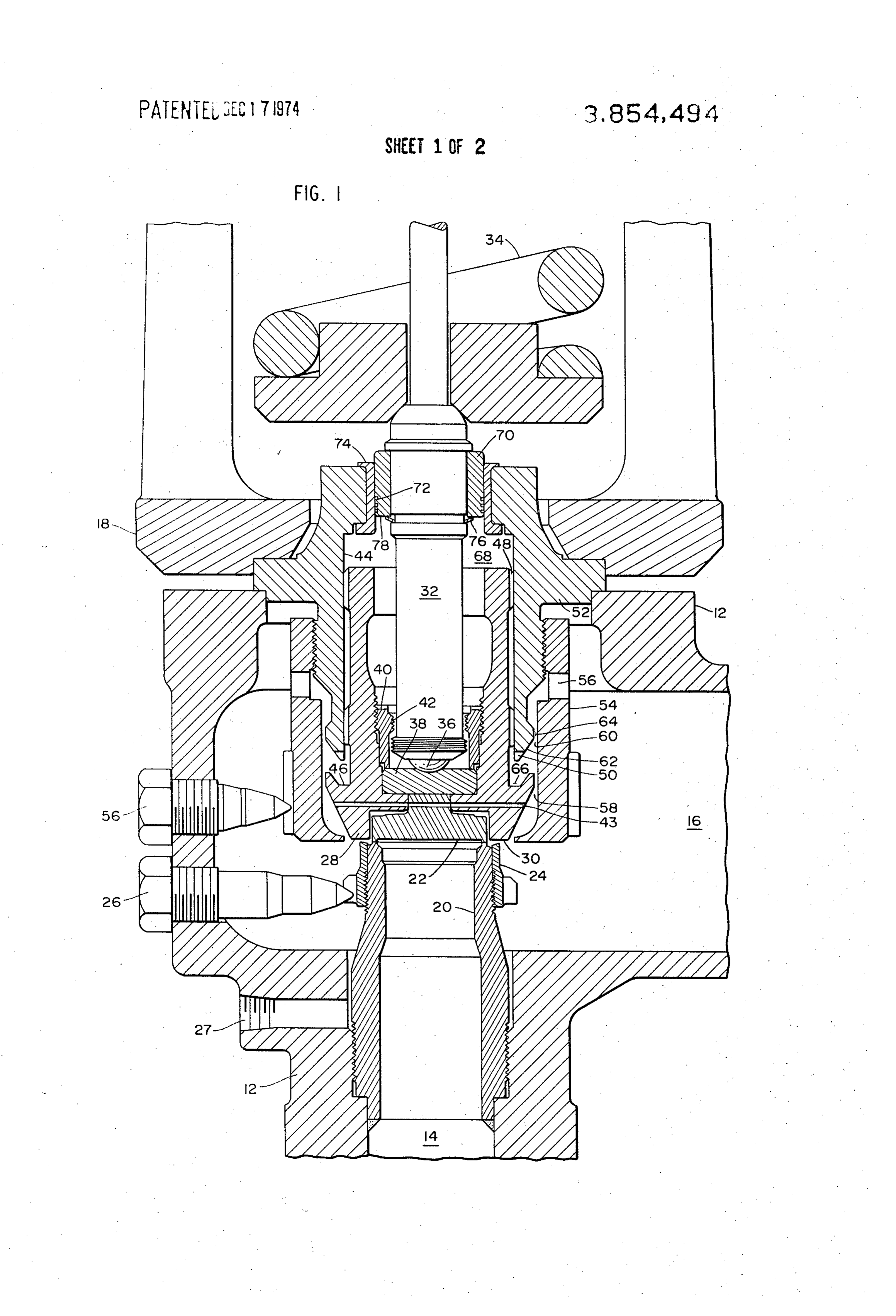
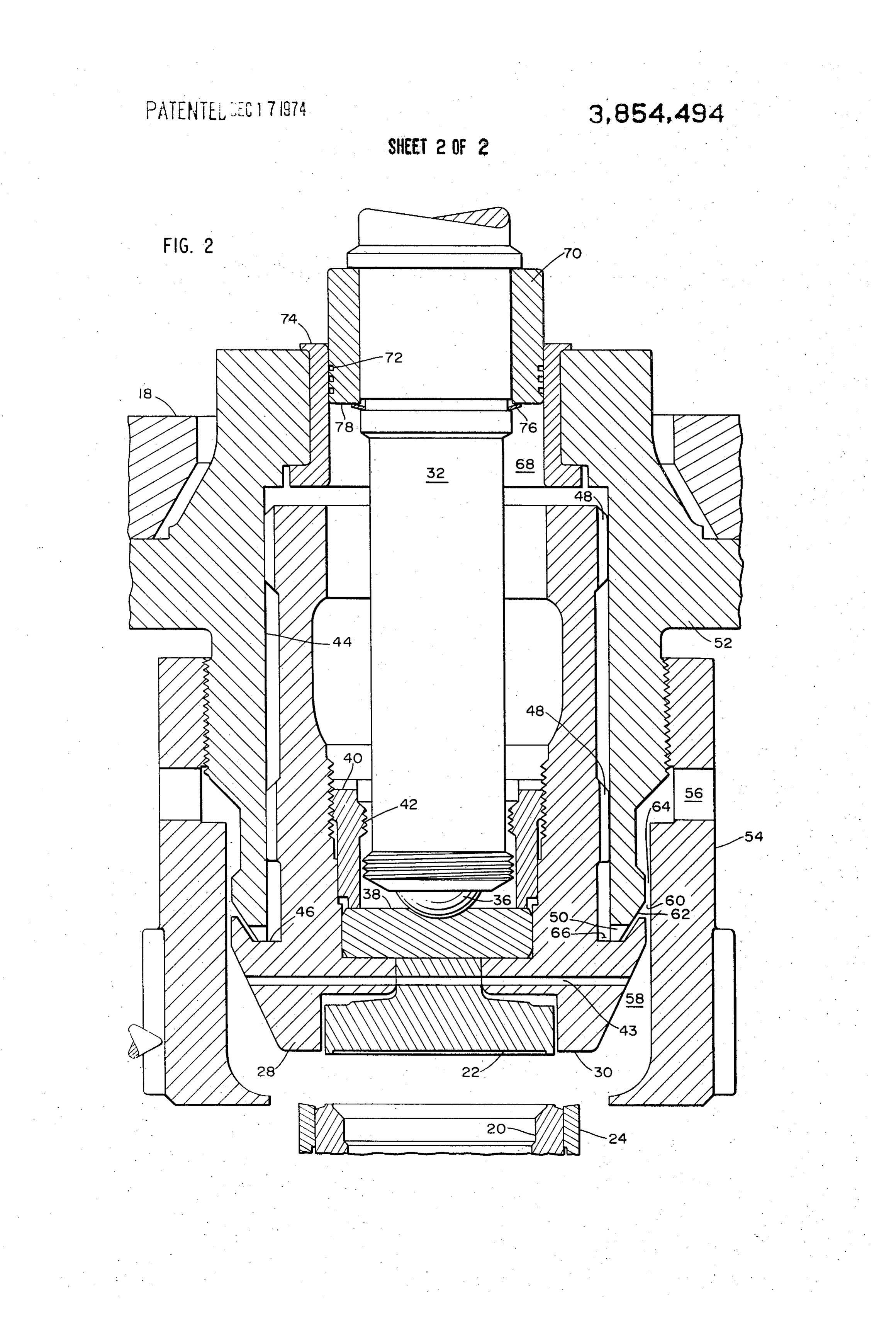
FIG. 1 is a sectional elevation of a safety relief valve to chambers 66 and 68.
embodying the features of this invention and showing At its narrowest point the passages 58 defines a flow the valve in the seated position. 5 area that is typically ten to twenty percent of the total FIG. 2 is an enlarged view of the central portion of flow area of the passage 58 plus the flow area located FIG. 1 showing the valve in the full lift position. between the nozzle ring 24 and the guide ring 54. Fur
DETALED DESCRIPTION OF THE PREFERRED
ther, the area of passage 60 always exceeds that of pas
EMBODIMENTS
sage 58. Expressed as a percentage, the area of passage
O 58 is approximately 60 to 80 percent of the area of pas
The valve shown in FIGS. and 2 is enclosed within sage 60.
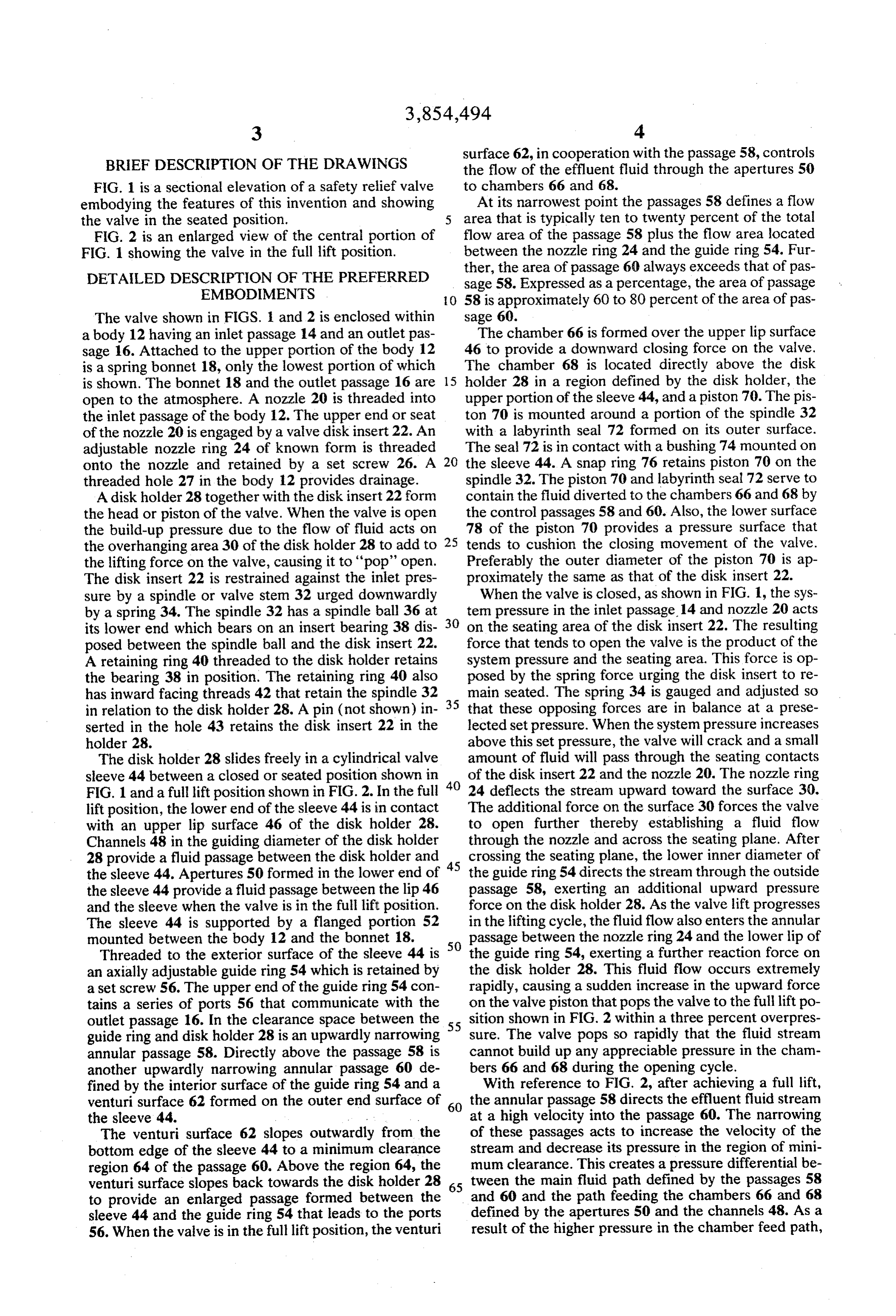
a body 12 having an inlet passage 14 and an outlet pas The chamber 66 is formed over the upper lip surface sage 16. Attached to the upper portion of the body 12 46 to provide a downward closing force on the valve. is a spring bonnet 18, only the lowest portion of which The chamber 68 is located directly above the disk is shown. The bonnet 18 and the outlet passage 16 are 15 holder 28 in a region defined by the disk holder, the open to the atmosphere. A nozzle 20 is threaded into upper portion of the sleeve 44, and a piston 70. The pis the inlet passage of the body 12. The upper end or seat ton 70 is mounted around a portion of the spindle 32 of the nozzle 20 is engaged by a valve disk insert 22. An with a labyrinth seal 72 formed on its outer surface. adjustable nozzle ring 24 of known form is threaded The seal 72 is in contact with a bushing 74 mounted on onto the nozzle and retained by a set screw 26. A 20 the sleeve 44. A snap ring 76 retains piston 70 on the threaded hole 27 in the body 12 provides drainage. spindle 32. The piston 70 and labyrinth seal 72 serve to A disk holder 28 together with the disk insert 22 form contain the fluid diverted to the chambers 66 and 68 by the head or piston of the valve. When the valve is open the control passages 58 and 60. Also, the lower surface the build-up pressure due to the flow of fluid acts on 25 78 of the piston 70 provides a pressure surface that the overhanging area 30 of the disk holder 28 to add to tends to cushion the closing movement of the valve. the lifting force on the valve, causing it to 'pop' open. Preferably the outer diameter of the piston 70 is ap The disk insert 22 is restrained against the inlet pres proximately the same as that of the disk insert 22. sure by a spindle or valve stem 32 urged downwardly When the valve is closed, as shown in FIG. 1, the sys by a spring 34. The spindle 32 has a spindle ball 36 at 30 tem pressure in the inlet passage 14 and nozzle 20 acts its lower end which bears on an insert bearing 38 dis on the seating area of the disk insert 22. The resulting posed between the spindle ball and the disk insert 22. force that tends to open the valve is the product of the A retaining ring 40 threaded to the disk holder retains system pressure and the seating area. This force is op the bearing 38 in position. The retaining ring 40 also posed by the spring force urging the disk insert to re has inward facing threads 42 that retain the spindle 32 35 main seated. The spring 34 is gauged and adjusted so in relation to the disk holder 28. A pin (not shown) in that these opposing forces are in balance at a prese serted in the hole 43 retains the disk insert 22 in the lected set pressure. When the system pressure increases holder 28. above this set pressure, the valve will crack and a small The disk holder 28 slides freely in a cylindrical valve amount of fluid will pass through the seating contacts sleeve 44 between a closed or seated position shown in 40 of the disk insert 22 and the nozzle 20. The nozzle ring FIG. 1 and a full lift position shown in FIG. 2. In the full 24 deflects the stream upward toward the surface 30. lift position, the lower end of the sleeve 44 is in contact The additional force on the surface 30 forces the valve with an upper lip surface 46 of the disk holder 28. to open further thereby establishing a fluid flow Channels 48 in the guiding diameter of the disk holder through the nozzle and across the seating plane. After 28 provide a fluid passage between the disk holder and 45 crossing the seating plane, the lower inner diameter of the sleeve 44. Apertures 50 formed in the lower end of the guide ring 54 directs the stream through the outside the sleeve 44 provide a fluid passage between the lip 46 passage 58, exerting an additional upward pressure and the sleeve when the valve is in the full lift position. force on the disk holder 28. As the valve lift progresses The sleeve 44 is supported by a flanged portion 52 in the lifting cycle, the fluid flow also enters the annular mounted between the body 12 and the bonnet 18. passage between the nozzle ring 24 and the lower lip of Threaded to the exterior surface of the sleeve 44 is 50 the guide ring 54, exerting a further reaction force on an axially adjustable guide ring 54 which is retained by the disk holder 28. This fluid flow occurs extremely a set screw 56. The upper end of the guide ring 54 con rapidly, causing a sudden increase in the upward force tains a series of ports 56 that communicate with the on the valve piston that pops the valve to the full lift po outlet passage 16. In the clearance space between the 55 sition shown in FIG. 2 within a three percent overpres guide ring and disk holder 28 is an upwardly narrowing sure. The valve pops so rapidly that the fluid stream annular passage 58. Directly above the passage 58 is cannot build up any appreciable pressure in the cham another upwardly narrowing annular passage 60 de bers 66 and 68 during the opening cycle.
fined by the interior surface of the guide ring 54 and a With reference to FIG. 2, after achieving a full lift, venturi surface 62 formed on the outer end surface of 60 the annular passage 58 directs the effluent fluid stream the sleeve 44. at a high velocity into the passage 60. The narrowing The venturi surface 62 slopes outwardly from the of these passages acts to increase the velocity of the bottom edge of the sleeve 44 to a minimum clearance stream and decrease its pressure in the region of mini region 64 of the passage 60. Above the region 64, the mum clearance. This creates a pressure differential be venturi surface slopes back towards the disk holder 28 65 tween the main fluid path defined by the passages 58 to provide an enlarged passage formed between the and 60 and the path feeding the chambers 66 and 68 sleeve 44 and the guide ring 54 that leads to the ports defined by the apertures 50 and the channels 48. As a 56. When the valve is in the full lift position, the venturi result of the higher pressure in the chamber feed path,
Page 6
S 6 the venturi surface diverts only a portion of the fluid to venting to atmosphere that achieves a full lift within a the chambers. Stated in terms of pressure, the pressure three percent over pressure and closes with a four per in the chambers 66 and 68 is maintained at a fraction cent blowdown. Additionally, the safety relief valve of of the system pressure. For purposes of illustration the invention is not prone to chatter, slam down clos only, if the system pressure is 1,500 psi, a typical pres ings, or premature closings. Various modifications of sure in the chambers 66 and 68 is approximately 40 to the invention will become apparent to those skilled in 50 percent as great, or 600 to 750 psi. This pressure the art from the foregoing description and accompany also depends on the disk position during its lifting cy ing drawings. Such modifications are intended to fall cle. within the scope of the appended claims. This pressure differential is highly desirable since the O What is claimed is:
valve would either slam shut and damage the valve 1. A safety relief valve having, in combination, parts, or close prematurely before a sufficient amount a body having inlet and outlet passages, a valve seat of fluid is released from the system, if a higher pressure communicating with said passages and a sleeve co is applied to the chambers. It should be noted that vari axial with the seat, said sleeve having a guide ring ations in the amount of fluid flowing through the pas 5 forming an axially adjustable extension thereof sages 58 and 60 will cause some change in the pressure with a port through the guide ring communicating differential. with the outlet passage, and During full lift, the principal forces keeping the valve a valve head slidable with clearance in the sleeve hav open are the pressure acting on the disk insert and the ing a stem slidable relative to said body with a por disk holder to its extreme outer diameter at the narrow tion in position to close upon said seat, said valve est region of the passage 58 and the reaction forces de head and sleeve defining a chamber, said sleeve veloped by the fluid acting on the nozzle ring 24 and having an outer venturiend surface forming a first the inner lower edge of the guide ring 54. Forces tend passage communicating with said port and narrow ing to close the valve are the spring compression and ing in the direction from the interior of the guide the controlled pressure in the chamber 66 and 68 act 25 ring toward the outlet passage. ing on the exposed upward facing surfaces. The pres sure in the chamber 66 acts over the upward facing lip characterized relief 2. A safety valve according to claim 1 further surface 46 from the guiding diameter of the disk holder slidably engaged withpiston by a attached to said stem and an upper portion of said sleeve.
28 to its widest diameter at the passage 58. The pres sure in the chamber 68 acts on the upper surfaces of 30 3. A safety relief valve according to claim 1 further the disk holder 28. This force, however, is partially off set by the same pressure acting on the downward facing characterized slidably engaged by a piston attached to said stem and with said body.
surface 78 of the piston 70 and other downward facing surfaces in the disk holder which are exposed to the characterized by saidvalve 4. A safety relief according to claim 2 further piston having a labyrinth seal dis pressure in the chamber 68. 35
When system pressure at the nozzle 20 decays, the posed between said piston and said upper sleeve por pressure acting on the disk holder face across its total tion. 5. A safety relief valve according to claim 1 wherein diameter at passage 58 also decays and fluid released said head has a sloped surface forming a second pas through the passages 58 and 60 to the exhaust ports 56 which controls the pressure in chamber 68 will have 40 sage communicating with the first passage, said second also decayed to a point where the closing forces de rowing inbeing passage located below the first passage and nar the same direction as the first passage.
scribed above become dominant and the disk holder starts to move downwardly. This is the beginning of the head 6. A safety valve according to claim 5 wherein said closing cycle. This in turn causes the lip surface 46 to sleevehasto aa lip extending beyond the lower end of the region between the first and second pas separate from the lower end of the sleeve 44 allowing 45 Sages.
more fluid to be diverted to the chambers. Therefore the pressure developed in the chambers does not de characterized 7. A safety relief valve according to claim 1 further crease in the same proportion as the pressures acting by a plurality of apertures formed in the on the disk insert 22 and the overhang area 30. The net lower edge of said sleeve.
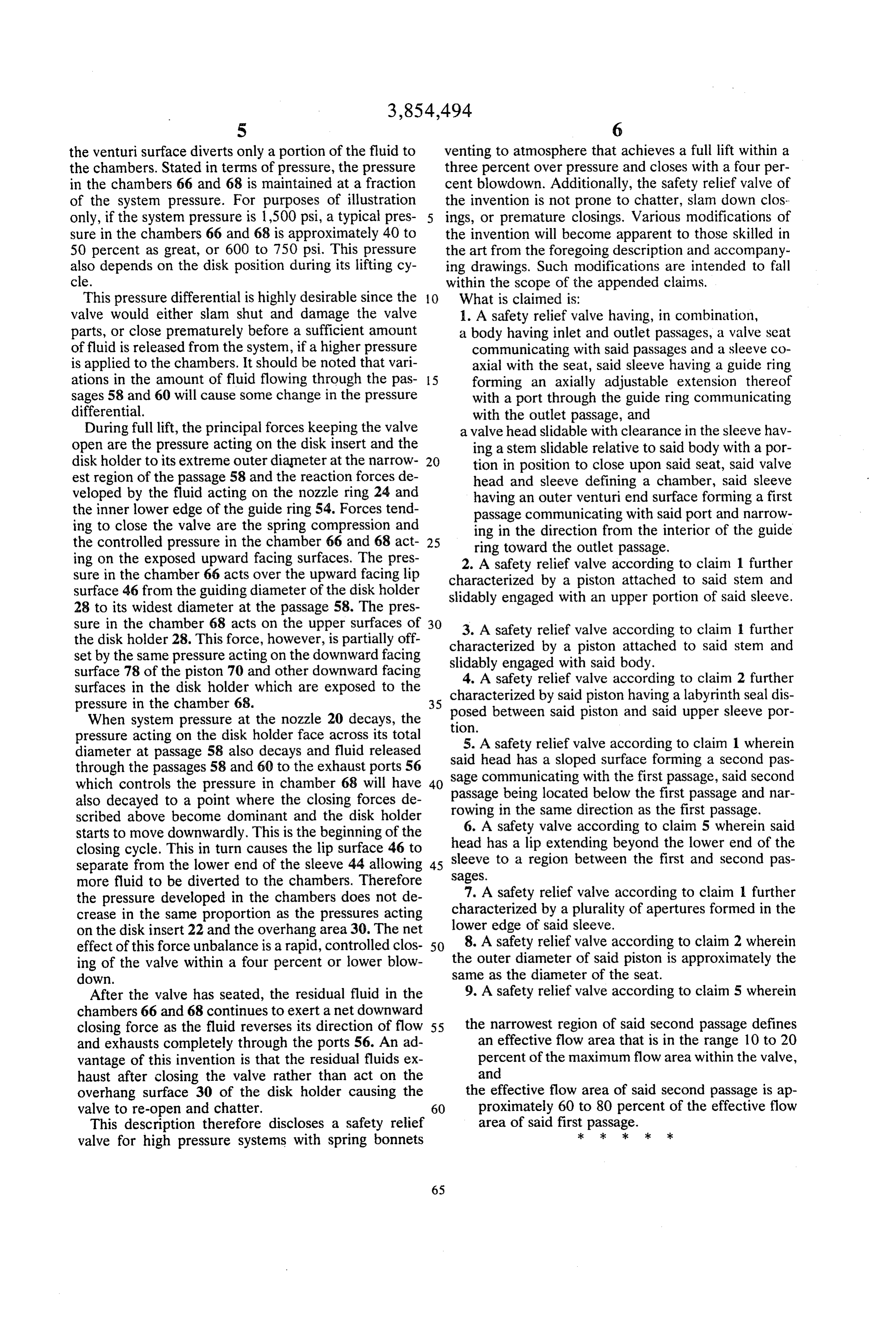
effect of this force unbalance is a rapid, controlled clos 50 8. A safety relief valve according to claim 2 wherein ing of the valve within a four percent or lower blow same the outer diameter of said piston is approximately the down. as the diameter of the seat. After the valve has seated, the residual fluid in the 9. A safety relief valve according to claim 5 wherein chambers 66 and 68 continues to exert a net downward closing force as the fluid reverses its direction of flow 55 the narrowest region of said second passage defines and exhausts completely through the ports 56. An ad an effective flow area that is in the range 10 to 20 vantage of this invention is that the residual fluids ex percent of the maximum flow area within the valve, haust after closing the valve rather than act on the and overhang surface 30 of the disk holder causing the the effective flow area of said second passage is ap valve to re-open and chatter. 60 proximately 60 to 80 percent of the effective flow This description therefore discloses a safety relief area of said firstk passage. valve for high pressure systems with spring bonnets k k sk
Provenance
- Collection
- Cited prior art
- Original PDF
- patentimages.storage.googleapis.com →
- Filed
- 1974-02-04
- Pages
- 6
- Method
- pdftotext (the PDF's own text layer) + pdftoppm 300dpi page scans
- Source
- Google Patents bibliographic record
- Granted
- 1974-12-17
- Inventors
- J Zahorsky; Crosby Valve and Gage Co
- Transcribed from
- patentimages.storage.googleapis.com →