patent · US3999379
Reduction of depressurization thrust termination jolt
28 December 1976
Page 1 — bibliographic record
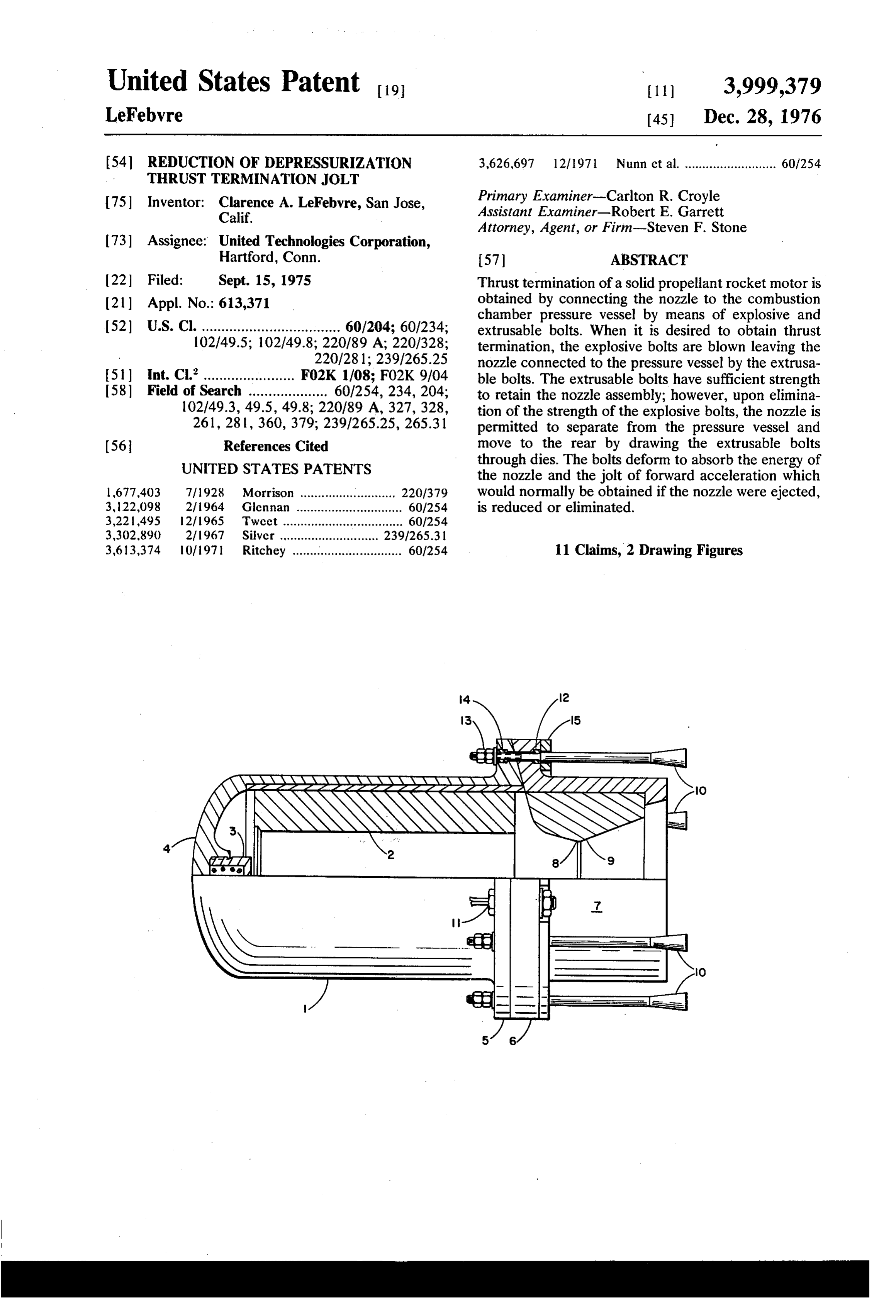
United States Patent to 3,999,379 LeFebvre 45 Dec. 28, 1976 54 REDUCTION OF DEPRESSURIZATION 3,626,697 12/1971 Nunn et al. .......................... 60/254
THRUST TERMINATION JOLT
(75 Inventor: Clarence A. LeFebvre, San Jose, Primary Examiner-Carlton R. Croyle Calif. Assistant Examiner-Robert E. Garrett
Attorney, Agent, or Firm-Steven F. Stone (73) Assignee: United Technologies Corporation,
Hartford, Conn. 57 ABSTRACT 22 Filed: Sept. 15, 1975 Thrust termination of a solid propellant rocket motor is 21 ) Appl. No.: 613,371 obtained by connecting the nozzle to the combustion chamber pressure vessel by means of explosive and (52) U.S. Cl. ................................... 60/204; 60/234; extrusable bolts. When it is desired to obtain thrust 102/49.5; 102/49.8; 220/89 A; 220/328; termination, the explosive bolts are blown leaving the 220/281; 239/265.25 nozzle connected to the pressure vessel by the extrusa
Int. Cl........................ F02K 1/08; FO2K9/04 ble bolts. The extrusable bolts have sufficient strength Field of Search .................... 60/254, 234, 204; to retain the nozzle assembly; however, upon elimina 102/49.3, 49.5, 49.8; 220/89 A, 327, 328, tion of the strength of the explosive bolts, the nozzle is 261, 281,360, 379; 239.1265.25, 265.31 permitted to separate from the pressure vessel and (56 References Cited move to the rear by drawing the extrusable bolts UNITED STATES PATENTS through dies. The bolts deform to absorb the energy of the nozzle and the jolt of forward acceleration which 1677,403 7/1928 Morrison ........................... 220/379 would normally be obtained if the nozzle were ejected, 3,122,098 2/1964 Glennan .............................. 60.1254 is reduced or eliminated. 3,221,495 12/1965 Tweet .................................. 60.1254 3,302,890 2/1967 Silver ............................ 2391265.31 3,613,374 10/1971 Ritchey ............................... 60/254 11 Claims, 2 Drawing Figures
aaaaaaaaae O
M A. S.
Page 2
Drawing sheet — no readable text.
Page 3
Drawing sheet — no readable text.
Page 4
debris in a direction in which it will not interfere with
REDUCTION OF DEPRESSURIZATION THRUST the rocket motor itself; however, the sudden release of TERMINATION JOLT a large volume of gas through the newly opened exit
BACKGROUND OF THE INVENTION
port of the rocket motor produces an extremely high 5 forward acceleration jolt. In many cases this jolt, as
Reaction motor burn times can be controlled by well as the rearward jolt produced by forward end various approaches depending upon the nature of the thrust termination, can be greater than can be tolerated fuel in the reaction motor. For example, if one or all of by the payload. Because of this effect, it is sometimes the fuel components of a reaction motor are in fluid not possible to open up a port large enough to maintain form, it is possible to control the burn time merely by 10 the pressure within the motor below the re-ignition shutting off the flow of one of these components. If, pressure.
however, the rocket motor is designed to use nonflow It is an object of this invention to provide for the ing fuel materials, such as is the case of a typical solid reduction or elimination of the jolt which occurs on the propellant rocket motor where a propellant grain of opening of a thrust termination port. particular size and configuration is located within a 15 It is another object of this invention to provide aft combustion chamber, it is not possible to control the end thrust termination in a manner which retains all the flow of a propellant component to the combustion advantages of the previous aft termination systems with chamber. In this type of rocket motor, the propellant is respect to damage from debris and at the same time designed to produce a predetermined thrusttime curve reduces or eliminates the undesirable acceleration jolt. but as mission requirements vary, it sometimes be 20 It is another object of this invention to provide for comes necessary to terminate the thrust prior to the thrust termination by depressurization which is capable time at which the entire propellant grain has been con of maintaining the pressure within the motor below the sumed. Thus, it becomes necessary to somehow extin re-ignition pressure.
guish the combustion process with the combustion Another object of this invention is to provide a chamber prior to consumption of the entire grain. One 25 rocket motor nozzle assembly capable of providing approach to accomplishing this is by physically quench aft-end thrust termination without an excessive accel ing the combustion process by injection of a liuqid such eration jolt.
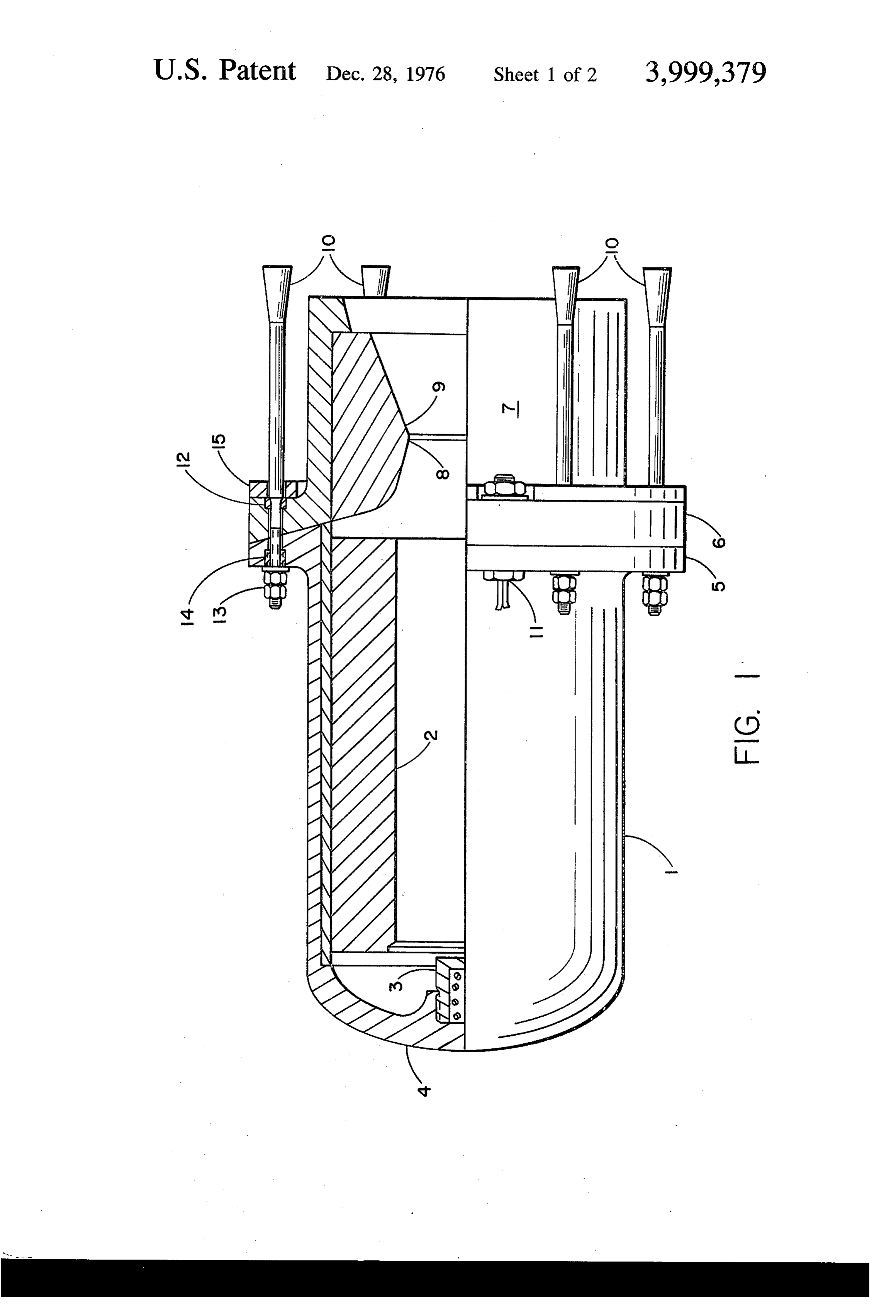
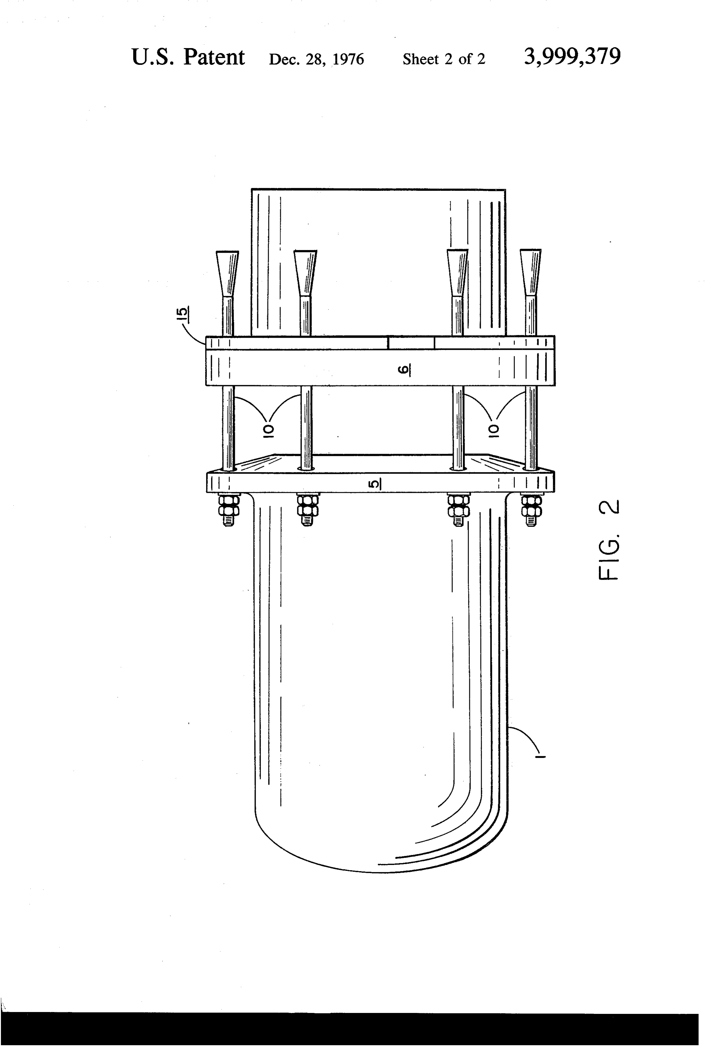
as water which will absorb a substantial amount of heat These and other objects of the invention will be upon vaporization and reduce the temperature of the readily apparent from the following description with grain below that at which it will continue to burn. This 30 reference to the accompanying drawings wherein: approach, of course, requires rapid injection of rela FIG. 1 is a side view, partly in sections, of one em tively large amounts of fluid and necessarily requires bodiment of this invention in its pre-termination con the carrying of an amount of combustion termination figuration; and, fluid on board. This necessarily detracts from the avail FIG. 2 is a side view of the embodiment of FIG. 1 in able payload. Another approach which is more readily 35 its post-termination configuration. used in large solid propellant rocket motors is to de DESCRIPTION OF THE INVENTION pressurize the combustion chamber. As a result of the burning characteristics of many solid propellants, the A rocket motor, according to the invention, com combustion process is pressure sensitive and it is prises a combustion chamber 1 containing a solid fuel known that a rapid depressurization of the combustion 40 grain 2 and igniter 3 mounted in the forward closure 4. chamber can extinguish the combustion process on the The aft end of the pressure vessel 1 terminates in a grain. Two approaches are used in accomplishing this - flange 5 adapted to engage a corresponding flange 6 on forward-end thrust termination and aft-end thrust ter the nozzle assembly 7 which comprises a throatportion mination. In the forward-end thrust termination sys 8 and exit cone portion 9. The flanges 5 and 6 are tem, a large port or a plurality of small ports are pro 45 provided with a series of annularly arranged holes vided through the forward closure which ports are which are adapted to receive either explosive bolts 11 sealed by plates adapted to be released, for example, by or extrusable bolts 10. In addition to functioning as a means of explosive bolts or Primacord. When the ap means for fastening the various components together, propriate signal is obtained, the explosive is detonated the flanges also perform a more significant function in and the port covers ejected, causing rapid depressuriza 50 that they will permit the combustion gases to escape, tion. The disadvantage with forward-end thrust termi upon the opening up of the thrust termination port, in nation is that it may interfere with the location of the a substantially symmetrical pattern such that no net payload, produce a sharp rearward or axially offset transverse thrust is produced which could effect the acceleration jolt, require a more complex internal ge path of travel of the motor. Thus, while it is usually ometry for the propellant in the forward end and the 55 desirable that no net transverse thrust be produced, it is debris produced by the port is ejected at a place where often desirable that some net axial thrust, either for it can cause damage to the rocket vehicle. Also, the ward or backward, be generated. Thus, for example, as port area is limited by the weight of propellant which is illustrated in the embodiment shown, the flanges are must be eliminated. Thus, in some cases, the mission beveled in the forward direction so that the gases es requirements prohibit the use of ports large enough to 60 caping on thrust termination will produce a forward prevent the chamber pressure from building up to the thrust component to counteract the rearward thrust re-ignition pressure where the motor will spontane produced by the gases escaping through the original ously re-ignite. nozzle. It is apparent, however, that the flanges can be When aft-end thrust termination is employed, one unbeveled or rearwardly beveled to produce any de approach is to explosively sever the nozzle assembly 65 sired thrust component which may be requested for any from the aft end of the rocket, thereby opening up a particular mission.
substantially larger exit port, causing rapid depressuri Each of the holes for receiving an extrusable bolt zation. This approach has the advantage of ejecting the contains an extrusion die 12 of slightly narrower diame
Page 5
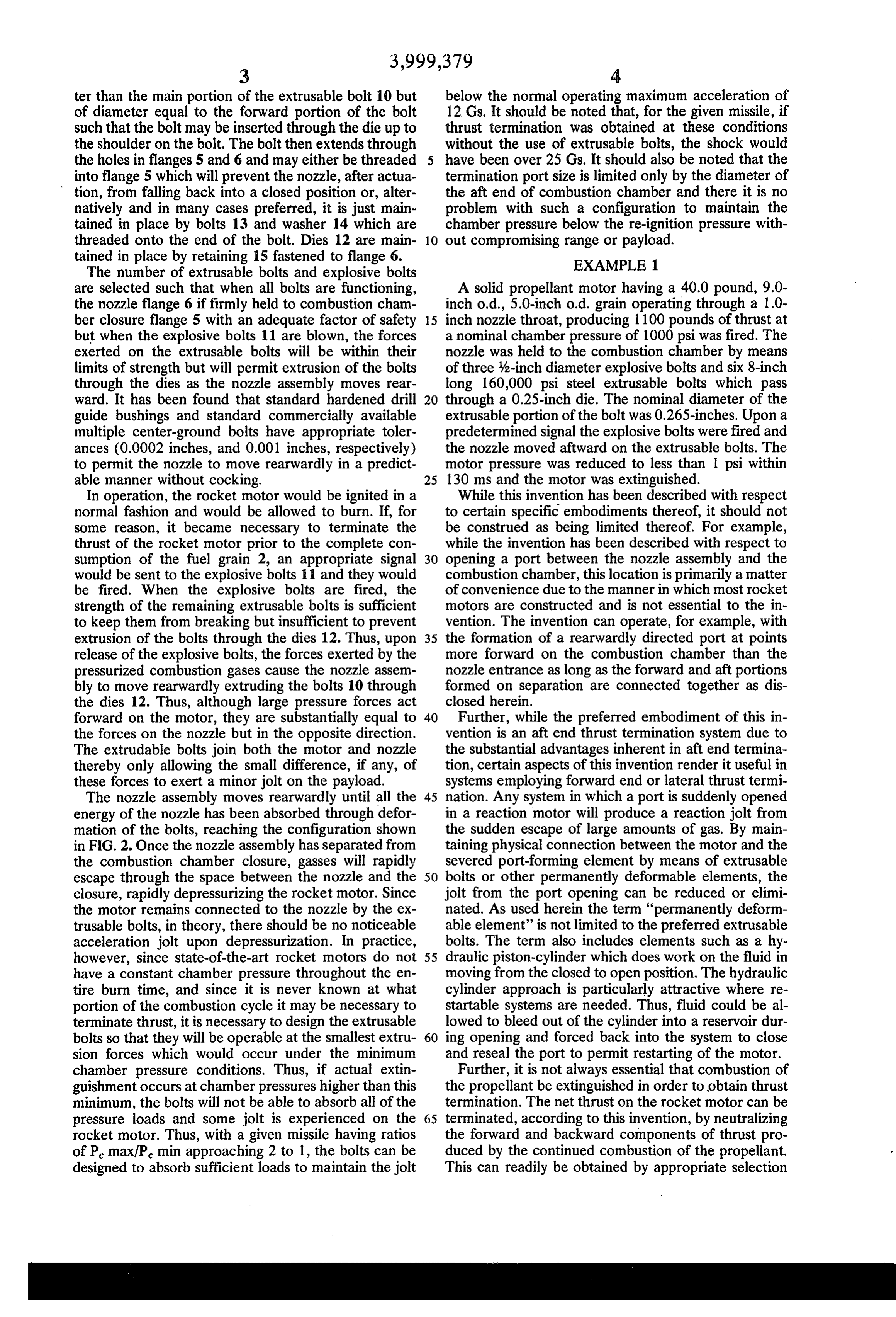
ter than the main portion of the extrusable bolt 10 but below the normal operating maximum acceleration of of diameter equal to the forward portion of the bolt 12 Gs. It should be noted that, for the given missile, if such that the bolt may be inserted through the die up to thrust termination was obtained at these conditions the shoulder on the bolt. The bolt then extends through without the use of extrusable bolts, the shock would the holes in flanges 5 and 6 and may either be threaded have been over 25Gs. It should also be noted that the into flange 5 which will prevent the nozzle, after actua termination port size is limited only by the diameter of tion, from falling back into a closed position or, alter the aft end of combustion chamber and there it is no natively and in many cases preferred, it is just main problem with such a configuration to maintain the tained in place by bolts 13 and washer 14 which are chamber pressure below the re-ignition pressure with threaded onto the end of the bolt. Dies 12 are main 10 out compromising range or payload. tained in place by retaining 15 fastened to flange 6. EXAMPLE 1. The number of extrusable bolts and explosive bolts are selected such that when all bolts are functioning, A solid propellant motor having a 40.0 pound, 9.0- the nozzle flange 6 if firmly held to combustion cham inch o.d., 5.0-inch o.d. grain operating through a 1.0- ber closure flange 5 with an adequate factor of safety 15 inch nozzle throat, producing 1 100 pounds of thrust at but when the explosive bolts 11 are blown, the forces a nominal chamber pressure of 1000 psi was fired. The exerted on the extrusable bolts will be within their nozzle was held to the combustion chamber by means limits of strength but will permit extrusion of the bolts of three 4-inch diameter explosive bolts and six 8-inch through the dies as the nozzle assembly moves rear long 160,000 psi steel extrusable bolts which pass ward. It has been found that standard hardened drill 20 through a 0.25-inch die. The nominal diameter of the guide bushings and standard commercially available extrusable portion of the bolt was 0.265-inches. Upon a multiple center-ground bolts have appropriate toler predetermined signal the explosive bolts were fired and ances (0.0002 inches, and 0.001 inches, respectively) the nozzle moved aftward on the extrusable bolts. The to permit the nozzle to move rearwardly in a predict motor pressure was reduced to less than 1 psi within able manner without cocking. 25 130 ms and the motor was extinguished. In operation, the rocket motor would be ignited in a While this invention has been described with respect normal fashion and would be allowed to burn. If, for to certain specific embodiments thereof, it should not some reason, it became necessary to terminate the be construed as being limited thereof. For example, thrust of the rocket motor prior to the complete con while the invention has been described with respect to sumption of the fuel grain 2, an appropriate signal 30 opening a port between the nozzle assembly and the would be sent to the explosive bolts 11 and they would combustion chamber, this location is primarily a matter be fired. When the explosive bolts are fired, the of convenience due to the manner in which most rocket strength of the remaining extrusable bolts is sufficient motors are constructed and is not essential to the in to keep them from breaking but insufficient to prevent vention. The invention can operate, for example, with extrusion of the bolts through the dies 12. Thus, upon 35 the formation of a rearwardly directed port at points release of the explosive bolts, the forces exerted by the more forward on the combustion chamber than the pressurized combustion gases cause the nozzle assem nozzle entrance as long as the forward and aft portions bly to move rearwardly extruding the bolts 10 through formed on separation are connected together as dis the dies 12. Thus, although large pressure forces act closed herein.
forward on the motor, they are substantially equal to 40 Further, while the preferred embodiment of this in the forces on the nozzle but in the opposite direction. vention is an aft end thrust termination system due to The extrudable bolts join both the motor and nozzle the substantial advantages inherent in aft end termina thereby only allowing the small difference, if any, of tion, certain aspects of this invention render it useful in these forces to exert a minor jolt on the payload. systems employing forward end or lateral thrust termi The nozzle assembly moves rearwardly until all the 45 nation. Any system in which a port is suddenly opened energy of the nozzle has been absorbed through defor in a reaction motor will produce a reaction jolt from mation of the bolts, reaching the configuration shown the sudden escape of large amounts of gas. By main in FIG. 2. Once the nozzle assembly has separated from taining physical connection between the motor and the the combustion chamber closure, gasses will rapidly severed port-forming element by means of extrusable escape through the space between the nozzle and the 50 bolts or other permanently deformable elements, the closure, rapidly depressurizing the rocket motor. Since jolt from the port opening can be reduced or elimi the motor remains connected to the nozzle by the ex nated. As used herein the term "permanently deform trusable bolts, in theory, there should be no noticeable able element' is not limited to the preferred extrusable acceleration jolt upon depressurization. In practice, bolts. The term also includes elements such as a hy however, since state-of-the-art rocket motors do not 55 draulic piston-cylinder which does work on the fluid in have a constant chamber pressure throughout the en moving from the closed to open position. The hydraulic tire burn time, and since it is never known at what cylinder approach is particularly attractive where re portion of the combustion cycle it may be necessary to startable systems are needed. Thus, fluid could be al terminate thrust, it is necessary to design the extrusable lowed to bleed out of the cylinder into a reservoir dur bolts so that they will be operable at the smallest extru 60 ing opening and forced back into the system to close sion forces which would occur under the minimum and reseal the port to permit restarting of the motor. chamber pressure conditions. Thus, if actual extin Further, it is not always essential that combustion of guishment occurs at chamber pressures higher than this the propellant be extinguished in order to obtain thrust minimum, the bolts will not be able to absorb all of the termination. The net thrust on the rocket motor can be pressure loads and some jolt is experienced on the 65 terminated, according to this invention, by neutralizing rocket motor. Thus, with a given missile having ratios the forward and backward components of thrust pro of P. max/P. min approaching 2 to 1, the bolts can be duced by the continued combustion of the propellant. designed to absorb sufficient loads to maintain the jolt This can readily be obtained by appropriate selection
Page 6
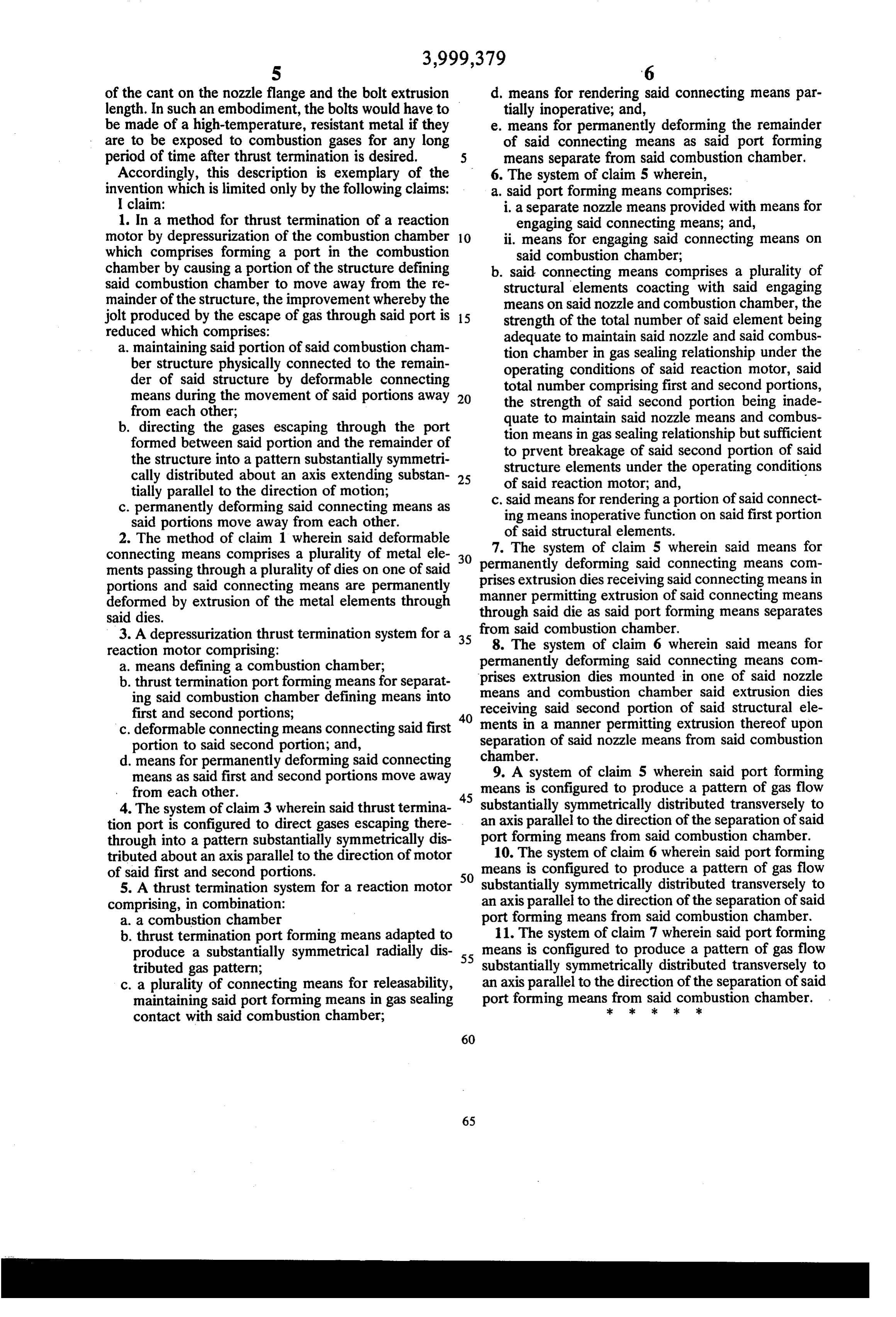
of the cant on the nozzle flange and the bolt extrusion d, means for rendering said connecting means par length. In such an embodiment, the bolts would have to tially inoperative; and, be made of a high-temperature, resistant metal if they e. means for permanently deforming the remainder are to be exposed to combustion gases for any long of said connecting means as said port forming period of time after thrust termination is desired. means separate from said combustion chamber. Accordingly, this description is exemplary of the 6. The system of claim 5 wherein, invention which is limited only by the following claims: a. said port forming means comprises: I claim: i. a separate nozzle means provided with means for 1. In a method for thrust termination of a reaction engaging said connecting means; and, motor by depressurization of the combustion chamber 10 ii. means for engaging said connecting means on which comprises forming a port in the combustion said combustion chamber; chamber by causing a portion of the structure defining b. said connecting means comprises a plurality of said combustion chamber to move away from the re structural elements coacting with said engaging mainder of the structure, the improvement whereby the means on said nozzle and combustion chamber, the jolt produced by the escape of gas through said port is 15 strength of the total number of said element being reduced which comprises: adequate to maintain said nozzle and said combus a. maintaining said portion of said combustion cham tion chamber in gas sealing relationship under the ber structure physically connected to the remain operating conditions of said reaction motor, said der of said structure by deformable connecting total number comprising first and second portions, means during the movement of said portions away 20 the strength of said second portion being inade from each other; quate to maintain said nozzle means and combus b. directing the gases escaping through the port tion means in gas sealing relationship but sufficient formed between said portion and the remainder of to prvent breakage of said second portion of said the structure into a pattern substantially symmetri structure elements under the operating conditions cally distributed about an axis extending substan 25 of said reaction motor; and, r tially parallel to the direction of motion; c. said means for rendering a portion of said connect c. permanently deforming said connecting means as ing means inoperative function on said first portion said portions move away from each other. of said structural elements.
2. The method of claim 1 wherein said deformable 7. The system of claim 5 wherein said means for connecting means comprises a plurality of metal ele 30 permanently ments passing through a plurality of dies on one of said prises extrusion deforming said connecting means com portions and said connecting means are permanently manner permitting dies receiving said connecting means in deformed by extrusion of the metal elements through through said die asextrusion of said connecting means said port forming means separates said dies.
3. A depressurization thrust termination system for a 35 from said combustion chamber.
reaction motor comprising: 8. The system of claim 6 wherein said means for a. means defining a combustion chamber; permanently deforming said connecting means com b. thrust termination portforming means for separat prises extrusion dies mounted in one of said nozzle means and combustion chamber said extrusion dies ing said combustion chamber defining means into receiving said second portion of said structural ele
c. deformable connecting means connecting said first ments in a manner permitting extrusion thereof upon portion to said second portion; and, separation of said nozzle means from said combustion d. means for permanently deforming said connecting chamber.
means as said first and second portions move away means 9. A system of claim 5 wherein said port forming
is configured to produce a pattern of gas flow 4. The system of claim 3 wherein said thrust termina substantially symmetrically distributed transversely to tion port is configured to direct gases escaping there an axis parallel to the direction of the separation of said through into a pattern substantially symmetrically dis port forming means from said combustion chamber. tributed about an axis parallel to the direction of motor means10. The system of claim 6 wherein said port forming
is configured to produce a pattern of gas flow 5. A thrust termination system for a reaction motor substantially symmetrically distributed transversely to comprising, in combination: an axis parallel to the direction of the separation of said a. a combustion chamber port forming means from said combustion chamber. b. thrust termination port forming means adapted to 11. The system of claim 7 wherein said port forming produce a substantially symmetrical radially dis 55 means is configured to produce a pattern of gas flow tributed gas pattern; substantially symmetrically distributed transversely to c. a plurality of connecting means for releasability, an axis parallel to the direction of the separation of said maintaining said port forming means in gas sealing port forming meansckfrom cle said
combustion
chamber.
contact with said combustion chamber;
Page 7
Page 1 of 3
UNITED STATES PATENT OFFICE
CERTIFICATE OF CORRECTION
Patent No. 3, 999, 379 Dated December 28, 1976
Inventor(s) Clarence C. Le Febvre
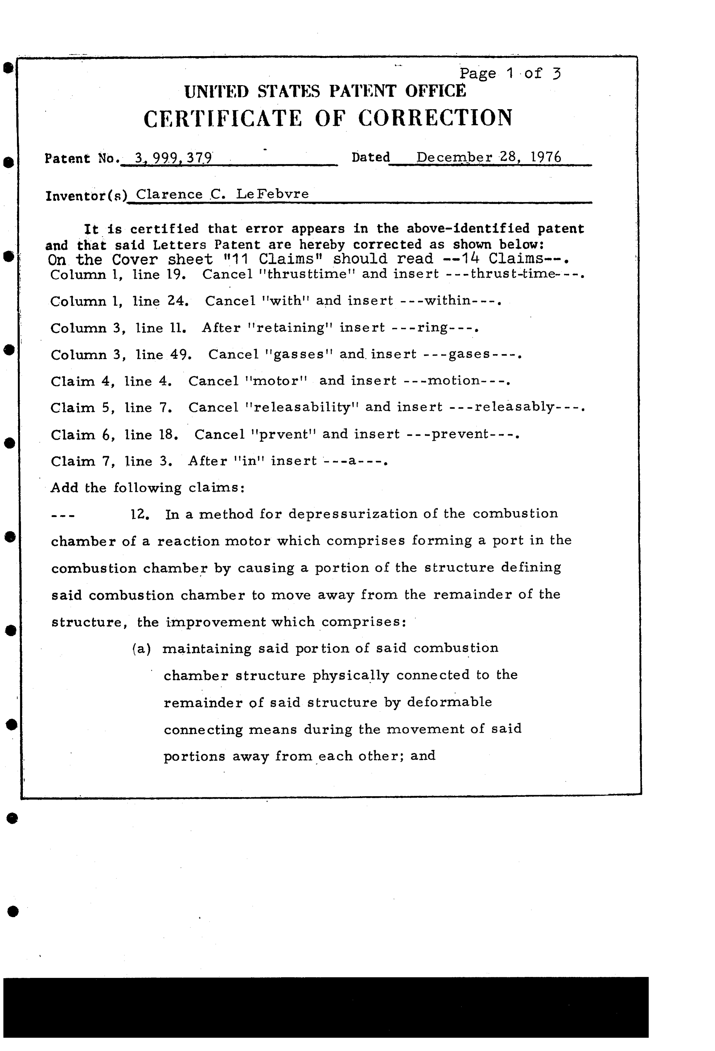
It is certified that error appears in the above-identified patent and that said Letters Patent are hereby corrected as shown below: On the Cover sheet "11 Claims" should read -- 14 Claims--. Column 1, line 19. Cancel 'thrusttime' and insert - - -thrust-time---. Column l, line 24. Cancel 'with" and insert ---within- - -. Column 3, line 11. After "retaining" insert --- ring---. Column 3, line 49. Cancel 'gasses' and insert ---gases - - -. Clain 4, line 4. Cancel 'motor' and insert ---notion---. Claim 5, line 7. Cancel 'releasability' and insert --- releasably---. Claim 6, line 18. Cancel 'prvent' and insert ---prevent---.
Add the following claims:
a 12. In a method for depressurization of the combustion chamber of a reaction motor which comprises forming a port in the combustion chamber by causing a portion of the structure defining said combustion chamber to move away from the remainder of the structure, the improvement which comprises:
(a) maintaining said portion of said combustion chamber structure physically connected to the remainder of said structure by deformable connecting means during the movement of said portions away from each other; and
Page 8
Page 2 of 3
UNITED STATES PATENT OFFICE
CERTIFICATE OF CORRECTION
Patent No. 3,999, 379 s Dated December 28, 1976. Inventor(s) Clarence A. LeFebvre
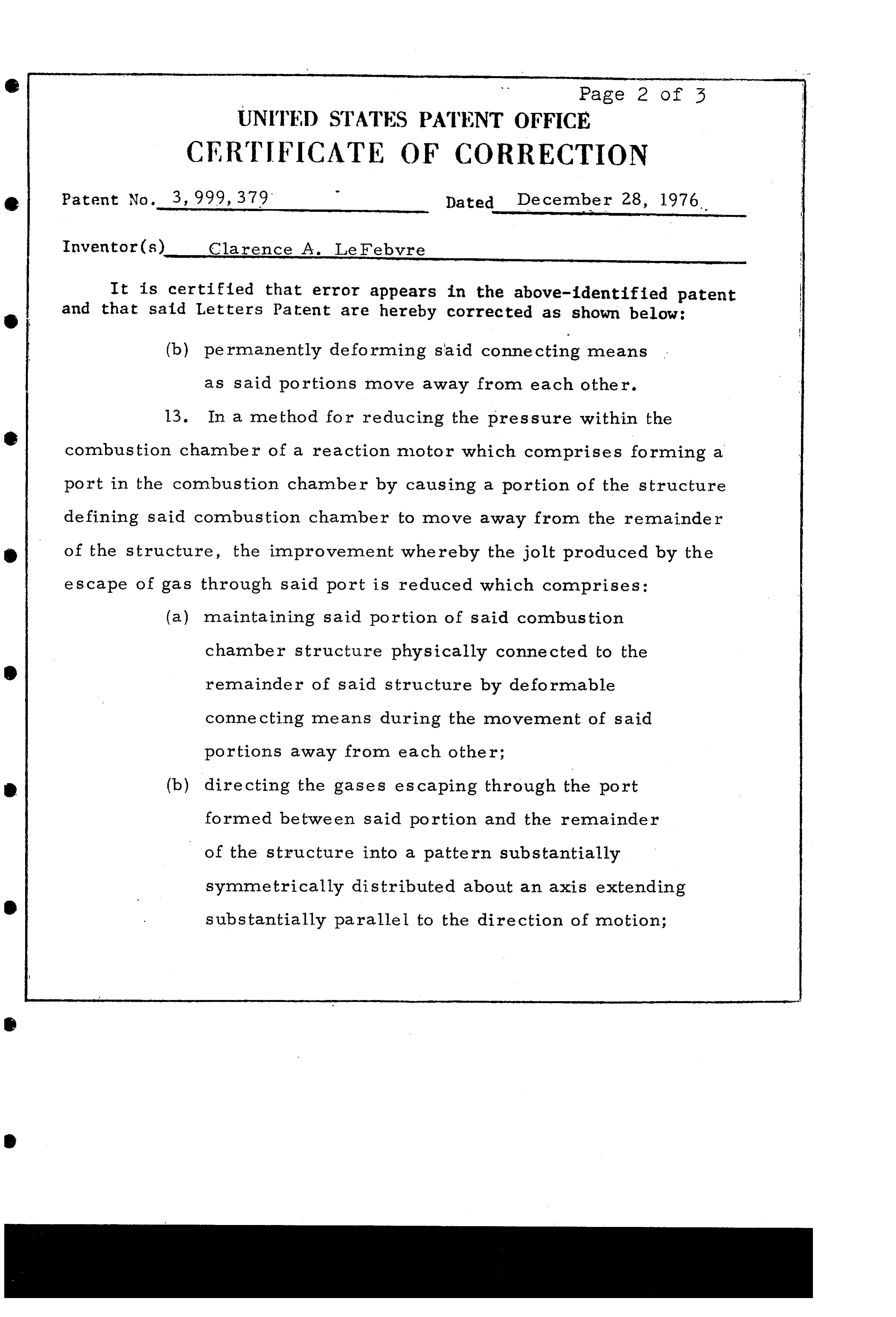
It is certified that error appears in the above-identified patent and that said Letters Patent are hereby corrected as shown below: (b) permanently deforming said connecting eaS as said portions move away from each other.
13. In a method for reducing the pressure within the combustion chamber of a reaction motor which comprises forming a port in the combustion chamber by causing a portion of the structure defining said combustion chamber to move away from the remainder of the structure, the improvement whereby the jolt produced by the escape of gas through said port is reduced which comprises: (a) maintaining said portion of said combustion chamber structure physically connected to the remainder of said structure by deformable connecting means during the movement of said portions away from each other;
directing the gases escaping through the port formed between said portion and the remainder of the structure into a pattern substantially symmetrically distributed about an axis extending substantially parallel to the direction of motion;
Page 9
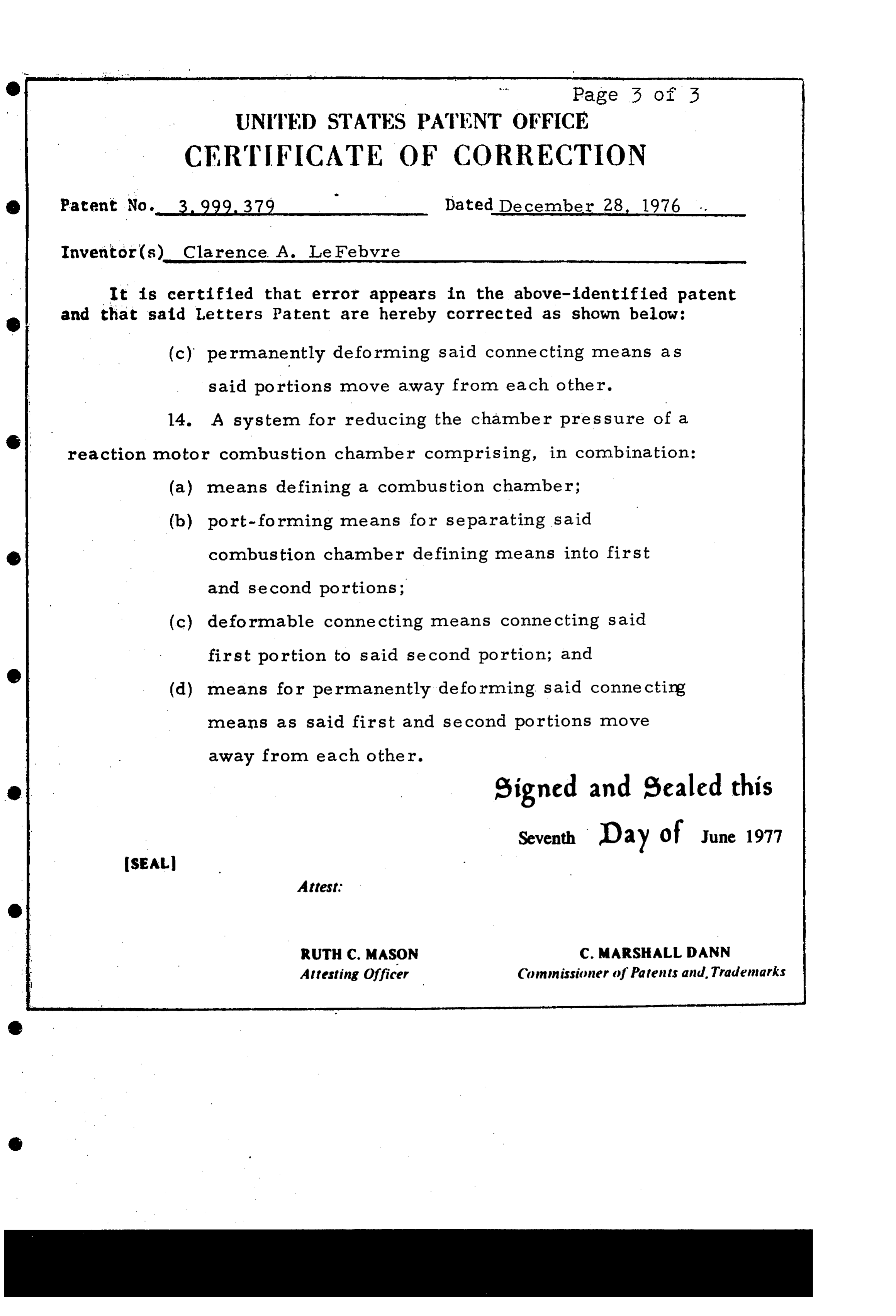
Page 3 of 5
UNITED STATES PATENT OFFICE
CERTIFICATE OF CORRECTION
Patent No. 3.999. 379 Dated December 28, 1976 . . Inventor(s) Clarence. A. Le Febvre
It is certified that error appears in the above-identified patent and that said Letters Patent are hereby corrected as shown below: (c) permanently deforming said connecting means as said portions move away from each other.
14. A system for reducing the chamber pressure of al reaction motor combustion chamber comprising, in combination: (a) means defining a combustion chamber;
(b) port-forming means for separating said combustion chamber defining means into first and second portions;
deformable connecting means connecting said first portion to said second portion; and means for permanently deforming said connecting means as said first and second portions nove away from each other.
eigned and Sealed this
Seventh Day of June 1977
Attesting Officer Commissioner of Patents and. Trademarks
Provenance
- Collection
- Cited prior art
- Original PDF
- patentimages.storage.googleapis.com →
- Filed
- 1975-09-15
- Pages
- 9
- Method
- pdftotext (the PDF's own text layer) + pdftoppm 300dpi page scans
- Source
- Google Patents bibliographic record
- Granted
- 1976-12-28
- Inventors
- Clarence A. LeFebvre; United Technologies Corp
- Transcribed from
- patentimages.storage.googleapis.com →