patent · US5305715
Supplement fuel generator for vehicle engines
26 April 1994
Page 1 — bibliographic record
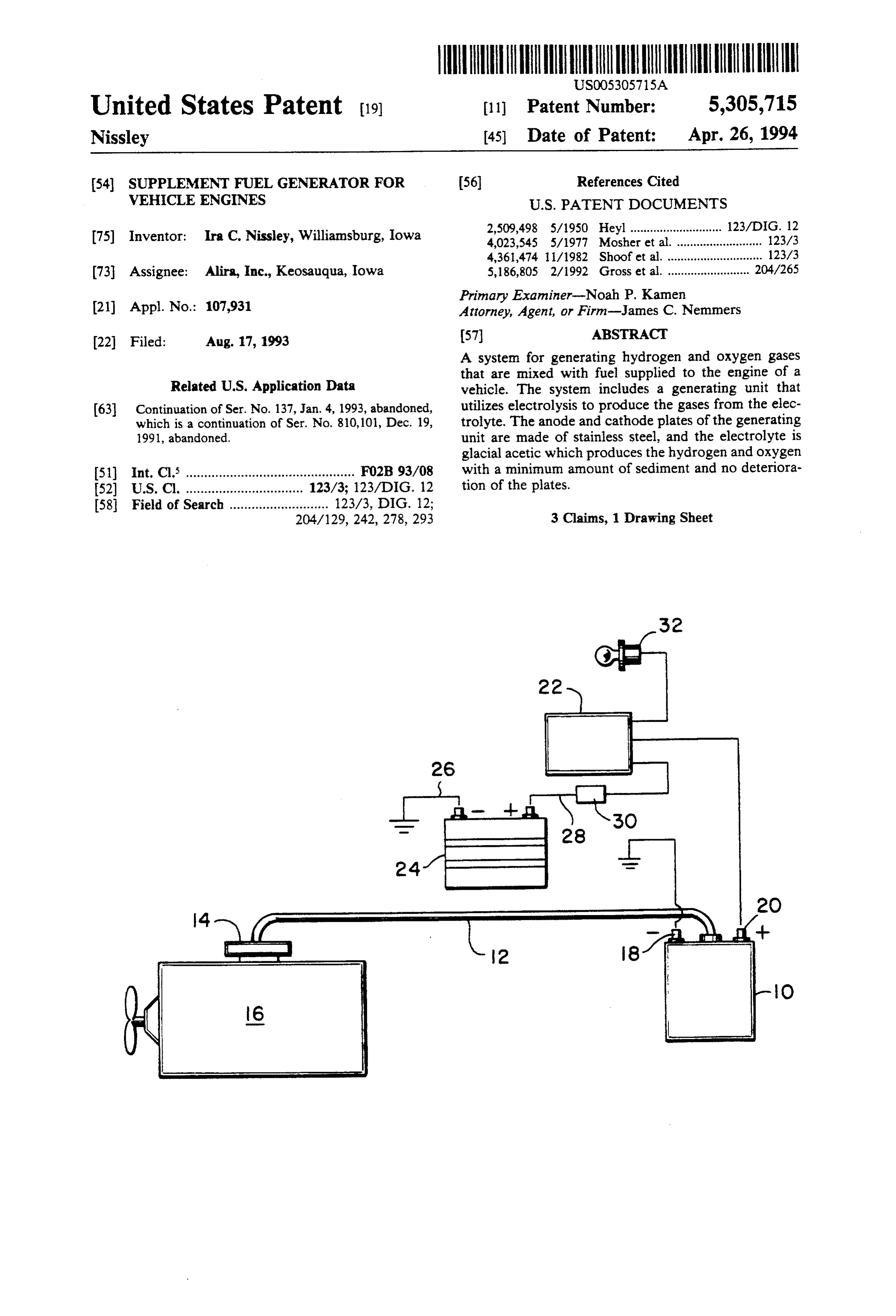
United States Patent 19) (11 Patent Number: 5,305,715 Nissley (45) Date of Patent: Apr. 26, 1994 (54) SUPPLEMENT FUEL GENERATOR FOR (56) References Cited VEHICLE ENGINES U.S. PATENT DOCUMENTS -- 2,509,498 5/1950 Heyl ............................ 123/DIG. 12 75) Inventor: Ira C. Nissley, Williamsburg, Iowa 4,023,545 5/1977 Mosher et al. .......................... 123A3 4,361,474 11/1982 Shoof et al. ............................. 123/3 (73 Assignee: Alira, Inc., Keosauqua, Iowa 5, 186,805 2/1992 Gross et al. ......................... 204/265 Primary Examiner-Noah P. Kamen (21) Appl. No.: 107,931 Attorney, Agent, or Firm-James C. Nemmers 22 Filed: Aug. 17, 1993 57 ABSTRACT A system for generating hydrogen and oxygen gases d U that are mixed with fuel supplied to the engine of a
Related U.S. Application Data vehicle. The system includes a generating unit that 63 Continuation of Ser. No. 137, Jan. 4, 1993, abandoned, utilizes electrolysis to produce the gases from the elec which is a continuation of Ser. No. 810,101, Dec. 19, trolyte. The anode and cathode plates of the generating 1991, abandoned. unit are made of stainless steel, and the electrolyte is glacial acetic which produces the hydrogen and oxygen 51) Int. Cl. .............................................. FO2B 93/08 with a minimum amount of sediment and no deteriora 52 U.S. Cl. ................................ 123/3; 123/DIG. 12 tion of the plates.
58 Field of Search ........................... 123/3, DIG. 12;
204/129, 242, 278, 293 3 Claims, 1 Drawing Sheet
Page 2
Drawing sheet — no readable text.
Page 3
BRIEF DESCRIPTION OF THE DRAWINGS
SUPPLEMENT FUEL GENERATOR FOR
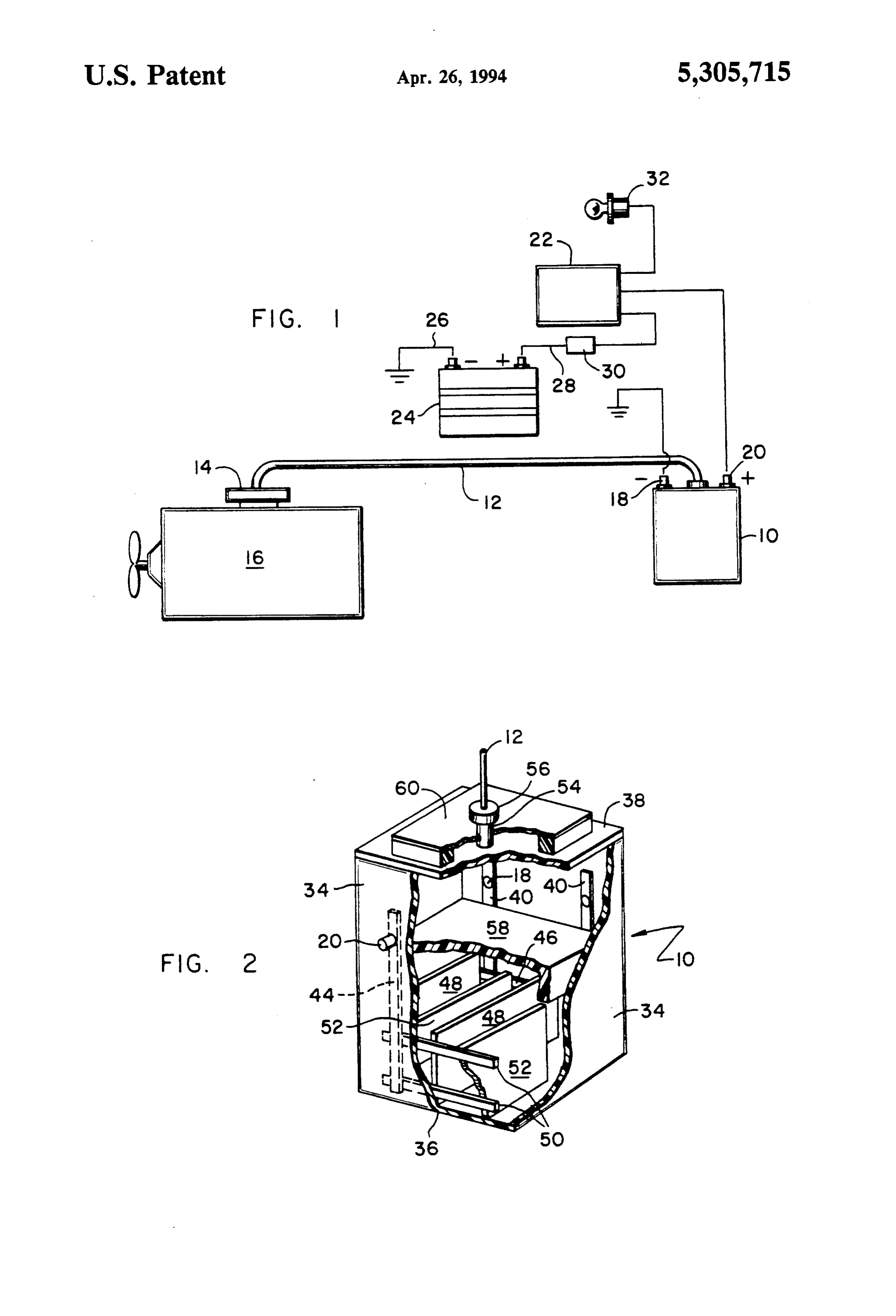
VEHICLE ENGINES FIG. 1 is a schematic diagram of the system of the invention illustrating the basic connections between the
This application is a continuation of application Ser. 5 generating unit and the vehicle engine; and No. 08/000,137, filed Jan. 4, 1993, now abandoned, FIG. 2 is a perspective view of a generating unit with which is a continuation of Ser. No. 07/810,101 filed a portion of the side walls removed to show the interior Dec. 19, 1991, now abandoned. Structure.
DESCRIPTION OF THE PREFERRED
EMBODIMENT OF THE INVENTION
There are a number of known systems for producing Referring to the drawings, FIG. 1 shows a schematic hydrogen and oxygen gases from an electrolyte, which diagram of a system suitable for employing the princi gases are used to supplement fuel supplied to a vehicle ples of the invention in which a generating unit, indi engine. The hydrogen and oxygen gases are generally 15 cated generally formed in a generating unit by electrolysis of the elec electrolyte that,bythroughthe reference numeral 10, contains an electrolysis, produces hydro trolyte. The gases are then introduced into the air intake gen and oxygen gases which re discharged through line of the engine. By supplementing the fuel, mileage is 12 that is connected to the air intake 14 of a vehicle improved and emissions reduced. engine 16. The generating unit 10 has a negative termi Although there are known numerous supplemental 20 nal 18 connected to ground and a positive terminal 20 fuel systems using the principles of electrolysis, they connected to a solenoid 22. The storage battery 24 of have not been commercially successful because of cost, the vehicle has its negative terminal 26 connected to problems with sediment contaminating the anode and ground and its positive terminal 28 connected through cathode plates, safety reasons and failure to produce breaker 30 to the solenoid 22. The ignition switch 32 of significant results. Numerous attempts have been made 25 the vehicle is connected to solenoid 22 so that the gen to correct the various problems. For example, in Mosh erating unit 10 will be connected in the circuit only if ier U.S. Pat. No. 4,023,545 and Glynn U.S. Pat. No. the ignition switch 32 is turned on.
4,442,801 "pusher' gases are used to sweep the plates in Referring now to FIG. 2, the generating unit 10 is a the generating unit. Systems using pusher gases are fluid container that has side walls 34, a bottom wall 36 relatively complicated. Also, attempts have been made 30 and a top wall 38. On opposite ones of the side walls 34 to raise the plates above the bottom of the convertor are secured vertical conductors 40 and 44 which are unit so that as sediment builds up in the unit it will not spaced apart and suitably secured to the side walls 34. contaminate the plates and reduce the efficiency of the Connected to at least one of the vertical conductors 40 unit. There have also been attempts at improving the on one side wall 34 is the negative terminal 18 that efficiency of these hydrogen generation units by 35 extends through the side wall 34 for connection in the changes in various materials in the plates and by using circuit as shown in FIG. 1. Similarly, vertical conduc various electrolyte compositions. Brown U.S Pat. No. tors 44 are secured to the side wall 34 opposite the 3,793,079 and Olivera U.S. Pat. No. 4,528,947 are exam vertical conductors 40, and the positive terminal 20 is ples of attempts to resolve the problems by changes in 40 the connected through the side wall 34 for connection in the composition of the electrolyte. However, none of circuit of FIG. 1.
these prior art teachings has resulted in an efficient, verticalWelded or otherwise suitably connected across the conductors 40 and 44 are one or more horizon workable unit that produces increased fuel efficiency tal conductors and reduced emissions. Especially in current times, erwise suitably 46 and 50, respectively. Welded or oth connected to the horizontal conductors reduction of emissions is not only important, but with increasing frequency, regulatory agencies are imposing 45 46 are a plurality of cathode plates 48, the bottom edges of which are preferably slightly above the bottom wall standards which must be met by vehicle manufacturers 36 of the generating unit 10. As best seen in FIG. 2, the and users. In addition, fuel efficiency standards are cathode plates 48 are vertically oriented and spaced repeatedly being raised and are becoming more difficult apart. Extending between the cathode plates 48 from to meet with cost effective techniques. 50 the opposite side wall 34 and welded to horizontal con There is therefore a need for ways to improve the fuel ductors 50 are a plurality of anode plates 52. The anode efficiency and to reduce engine emissions of vehicles. plates 52 are alternately spaced with the cathode plates There is a further need for producing improved fuel 48, and similar to the cathode plates 48 the bottom edges efficiencies and reduced emissions in a cost effective of anode plates 52 are positioned slightly above the manner. Any such ways of improving fuel efficiency 55 bottom wall 36 of the generating unit 10. and reducing emissions should also be easy to use and Preferably, the cathode plates 48 and anode plates 52 maintain and meet all safety criteria. are constructed of stainless steel of 14 or 16 gauge. SUMMARY OF THE INVENTION Stainless steel provides the necessary structural integ rity required where the unit is to be installed in vehicles.
In the system of the invention, the hydrogen generat The size and spacing of the cathode plates 48 and ing unit is provided with a plurality of vertically ori anode plates 52 are somewhat critical, with the size, ented cathode and anode plates constructed of a non number and spacing of the plates being determined by reactive material, such as stainless steel. The unit con the size and capacity of the generating unit 10 that will tains an electrolyte consisting of glacial acetic acid and be needed. For example, if the generating unit 10 has a distilled water. This electrolyte is noncaustic and pro 65 bottom wall 36 that is approximately nine (9) inches duces a unit that will operate over an extended period of square and the height of the side walls 34 is nine (9) time with practically no deterioration of the plates and inches, I have found that the use of two cathode plates little or no sediment. 48 and three anode plates 52, each approximately three
Page 4
(3) inches by five (5) inches and spaced approximately combustion chambers are cleaner than engines which one-half () inch apart, will produce the desired results. do not employ a generating unit of the invention. Thus, Also, a generating unit 10 that is 9"X9'x16' will re use of the generating unit of the invention will allow the quire two cathode plates 48 and three anode plates 52, vehicle engine to develop more horse power with each 5"x7' and spaced approximately one (1) inch greater efficiency, run cleaner and emit less toxic pollut apart, while a unit 10 that is 11" x 11" x 16" requires altS.
three cathode plates 48 and four anode plates 52, each Since the generating unit and system of the invention 7"X9" and spaced approximately one (1) inch apart. does not store hydrogen at any time, but merely injects The type of electrolyte used in the generating unit 10 hydrogen and oxygen directly into the engine as they is critical. It has been determined that the use of a solu 10 are produced, the unit is completely safe. When the tion of acetic acid as an electrolyte is essential. Acetic engine is not operating, the generating unit is similarly acid is a noncaustic electrolyte and will not react with not operating. It is therefore quite apparent that use of the cathode plates 48 and anode plates 52. Thus, even the generating unit of the invention will produce signifi after extended use, no deterioration of the plates 48 or cant improvements in vehicle performance, power, fuel 52 occurs. Moreover, acetic acid provides the necessary 15 efficiency and reduced emissions. electron transfer for the electrolysis process, but the Having thus described the invention in connection acetic acid does not break down, and therefore there is with the preferred embodiment thereof, it will be evi little or no sediment produced in the generating unit 10 dent to those skilled in the art that various revisions and even after extended use. In prior art devices, sediment modifications can be made to the preferred embodiment has been a problem. I have found that an electrolyte 20 without departing from the spirit and scope of the in containing 1% to 4% acetic acid in distilled water will vention. It is my intention, however, that all such revi produce optimum results. Glacial acetic acid is approxi sions and modifications as are obvious to those skilled in mately 90% acetic acid and 10% distilled water and is the art will be included within the scope of the follow readily available for use as an electrolyte in the genera ing claims.
tion unit 10 of the invention. With a concentration of 25 What is claimed is as follows: acetic acid in the foregoing indicated range, the electro 1. A gas generating unit for use with vehicle engines lyte will keep the cathode plates 48 and anode plates 52 having a source of electrical energy and also having an clean, and the acetic acid solution will create its own buffer and removes the gas bubbles from the plates 48 intake for supplying a fuel-air mixture to the engine, and 52. Concentrations of 1% to 4% of acetic acid will 30 said unit comprising an electrolysis unit having bottom produce the optimum results. This concentration of and top walls joined by side walls to form an enclosed acetic acid in distilled water will put the proper pressure binedawith unit, positive terminal and a negative terminal com said unit for connecting the unit in circuit on the chemical reaction occurring in the electrolysis with the source process, and thus produce higher amounts of hydrogen ergy to the unit of electrical energy to supply said en only when the engine is operating, at gas. Concentrations of acetic acid above 4% will func 35 least one vertically-oriented cathode plate in said unit tion, but may cause overheating in the generator. On the other hand, concentrations of acetic acid less than connected to the negative terminal of the electrolysis 1% will not generate sufficient electron transfer to pro unit, at least one vertically-oriented anode plate spaced duce the necessary hydrogen gas to make an efficiently from the cathode plate in said unit and connected to the operating generating unit. positive terminal of the electrolysis unit, said cathode In order to capture the hydrogen gas produced in the and anode plates being made of stainless steel, an elec generating unit 10, generating unit 10 has a discharge trolyte solution contained in said enclosed electrolysis tube 54 containing a removable cap 56 that is in turn unit and completely submerging the cathode and anode connected to the air tube 12. Removable cap 56 pro plates, the electrolyte consisting only of acetic acid and vides for introduction of the electrolyte into the interior 45 distilled water in a concentration of one to four percent of the generating unit 10. I also prefer to provide a of acetic acid, and means for connecting the electrolysis honeycomb cover 58 above the cathode plates 48 and unit to the air intake of the engine to convey gases anode plates 52 to prevent excessive splashing of the generated from the electrolyte solution to said engine electrolyte and maintain the solution over the plates 48 air intake.
and 52. In addition, an air filter 60 is preferably pro 50 2. The gas generation of claim 1 in which there is vided on the top wall 38 surrounding the discharge tube provided a cover positioned over the electrolyte solu 54 in order to keep dust and other impurities out of the tion in the unit, the cover allowing the passage of the system. gas generated within the unit by the electrolyte while Preliminary tests using a generating unit constructed maintaining the electrolyte solution over the cathode according to the principles of the invention have pro 55 and anode plates and preventing excessive splashing of duced reductions in toxic exhaust emissions as high as the electrolyte solution.
76% while increasing favorable oxygen emissions by 3. The gas generation unit of claim 2 in which there is 80%. Units have also increased fuel mileage from 16% a discharge tube extending through the top wall of the to 31% depending upon the particular vehicle and the unit to convey the gases generated from the electrolyte driving habits of the operator. Addition of hydrogen solution to the engine air intake and there is combined gas and oxygen into the vehicle engine increases the with the top wall surrounding the discharge tube an air burning efficiency of both diesel and gasoline fuels. filter to prevent impurities sk from entering the unit.
Moreover, it has been shown that injector nozzles and
Provenance
- Collection
- Cited prior art
- Original PDF
- patentimages.storage.googleapis.com →
- Filed
- 1993-08-17
- Pages
- 4
- Method
- pdftotext (the PDF's own text layer) + pdftoppm 300dpi page scans
- Source
- Google Patents bibliographic record
- Granted
- 1994-04-26
- Inventors
- Ira C. Nissley; Alira Inc
- Transcribed from
- patentimages.storage.googleapis.com →