patent · US4028213
Variable gap anode assembly for electrolytic cells
7 June 1977
Page 1 — bibliographic record
United States Patent (19) 11 4,028,213 Ford 45 June 7, 1977 54) WARIABLE GAP ANODE ASSEMBLY FOR Primary Examiner-John H. Mack ELECTROLYTC CELLS Assistant Examiner-D. R. Valentine Attorney, Agent, or Firm-James B. Haglind; Donald F.
(75) Inventor: James M. Ford, Cleveland, Tenn. Clements; Thomas P. O'Day (73) Assignee: Olin Corporation, New Haven,
Conn. 57 ABSTRACT 22) Filed: Feb. 9, 1976 An electrolytic cell of the type having a plurality of anodes and at least one foraminous cathode. The cell 21 Appl. No.: 656,166 includes an anode mounting plate to which the anodes (52) U.S. C. ............................... 204/286; 204/225; are connected. The anodes have associated therewith a 204/266 mounting post which is attached to the anode mounting 51) Int. C.’..................... C25B 11/00; C25C 7700 plate of the cell by attaching means which can be used (58) Field of Search .......... 204/252,266, 260, 212, to vary the spacing between the anodes for reception of 204/225, 280-284, 286 the cathodes. The attaching means includes a crank (56) References Cited member which, upon rotation thereof, moves the mounting posts laterally with respect to the anode
UNITED STATES PATENTS mounting plate.
3,941,676 3/1976 Macken ......................... 204/252 X 10 Claims, 3 Drawing Figures
sSNN
YZ StrayararE. SSS X
Page 2
Drawing sheet — no readable text.
Page 3
Drawing sheet — no readable text.
Page 4
manually or by insertion of the cathodes between them
VARABLE GAP ANODE ASSEMBLY FOR with the use of spacing elements. ELECTROLYTC CELLS A similar approach is disclosed in U.S. Pat. No.
BACKGROUND OF THE INVENTION
cording to the disclosure of this patent, each of the
This invention generally relates to an electrolytic cell anodes includes adjustable anode sections provided of the type which includes a cell enclosure, a plurality with independent anode mounts for each section. The of anodes, a foraminous cathode extending between anode mounts extend through an enlarged aperture or adjacent anodes, and a diaphragm or membrane in the slot in the base plate and are secured thereto by means anode-cathode gap. More particularly, this invention O of a threaded nut. When the nut is untightened, each relates to such electrolytic cells having an improved anode section can be moved to vary the width of the anode mounting structure for attaching anodes to an anodes so that the space between adjacent anodes is anode mounting plate so the anodes can be moved enlarged to permit installation of the cathodes or mini laterally with respect to the anode mounting plate to mized to narrow the distance between the anode and adjust the anode-cathode gap. 15 the diaphragm surface on the cathode. In a Hooker-type electrolytic cell, for example, the It is to be noted that according to the arrangements anodes are attached to an anode mounting plate which discussed above, no mechanism is provided which will is usually the base of the cell. Foraminous iron or steel positively move the anodes. According to the described cathodes coated with a diaphragm are suspended from arrangements after the nut is loosened, the anodes must the sides of the cell body and extend between adjacent 20 be either moved manually or by cathode as it is inserted anodes. between the anodes.
In cases where the anodes are fabricated from graph Accordingly, it is an object of this invention to pro ite, the anodes are secured with lead and an asphaltic vide an improved anode mounting structure for attach sealer in the cell base. Recently, the graphite anodes ing anodes of an electrolytic cell to an anode mounting have been replaced by metallic anodes having a suit 25 plate wherein the anodes can be adjusted to vary the able conducting coating on the outer surface of the anode-cathode gap.
anode. It is a further object of this invention to provide an U.S. Pat. No. 3,591,483, issued July 6, 1971, to Loft improved adjustable anode mounting structure for use field, et al, describes one method of attaching metallic in connection with electrolytic cells wherein the anodes to the cell base. According to this patent, the 30 mounting structure can be used to positively move the cell base is of conducting material, the interior of which anodes.
is covered with an electrically non-conductive sheet. According to the broad aspects of the invention, The anodes include an anode riser having a flange in attaching means are provided for attaching the mount the lower portion thereof and a portion extending from ing posts of an anode of an electrolytic cell to an anode the flange through an aperture in the cell base. The 35 mounting plate. The attaching means includes a por anode posts are threaded and secured to the cell base tion extending through the anode mounting plate and with threaded nuts. adapted for rotation therein whereby upon rotation With the anodes mounted in the manner described thereof lateral movement with respect to the base plate above, they cannot be adjusted laterally with respect to is imparted to the anode.
the base plate to vary the anode-cathode gap. Substan 40 The attaching means preferably includes a crank tial space is required between the anode and the cath having one end extending through the anode mounting ode during assembly of the cell to prevent scraping plate and the other end mounted in the mounting post. between them due to misalignment or dimensional Rotation of the end of the crank extending through the deficiencies. Such scraping is undesirable because it plate member will result in movement of the anode may result in the breaking of the diaphragm which 45 laterally of the plate member.
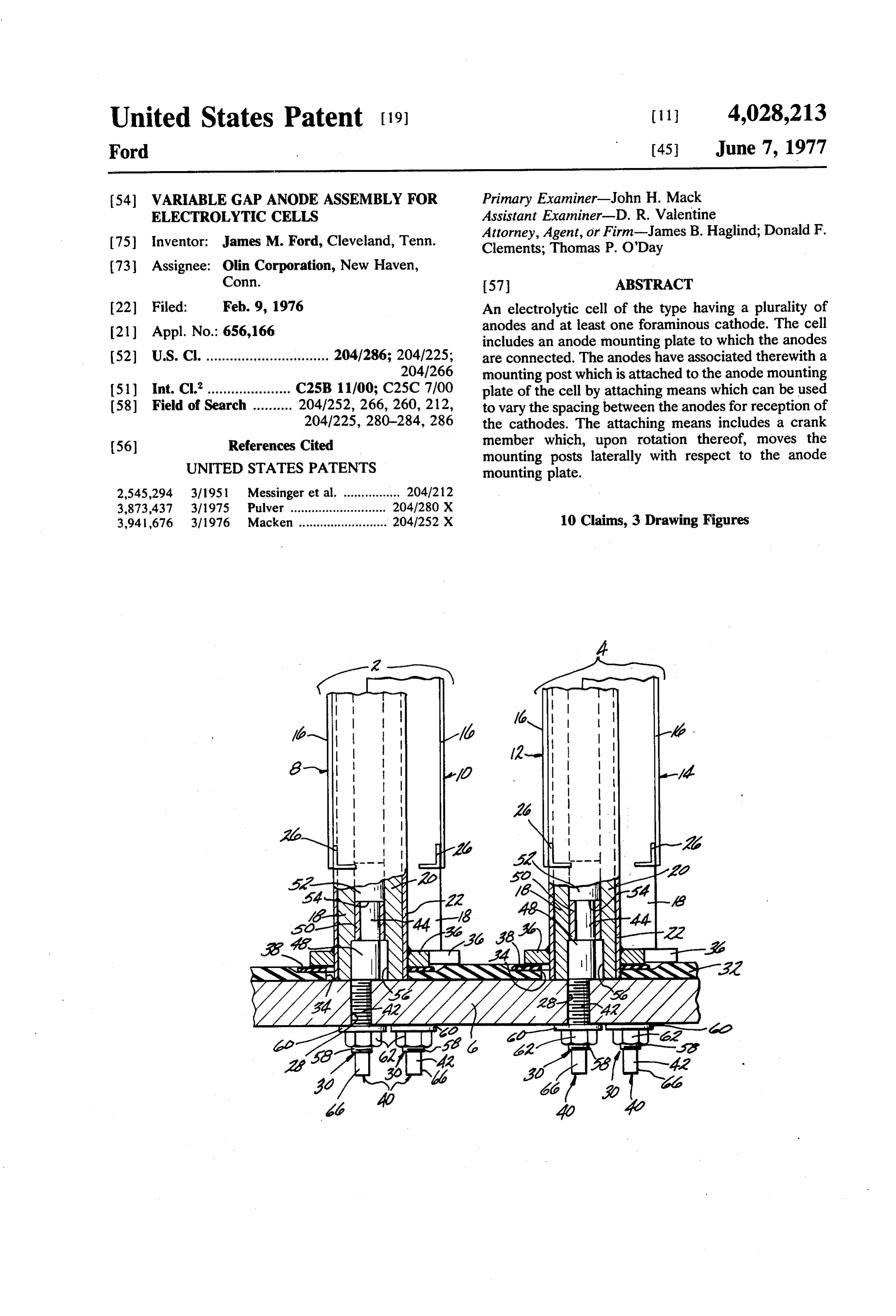
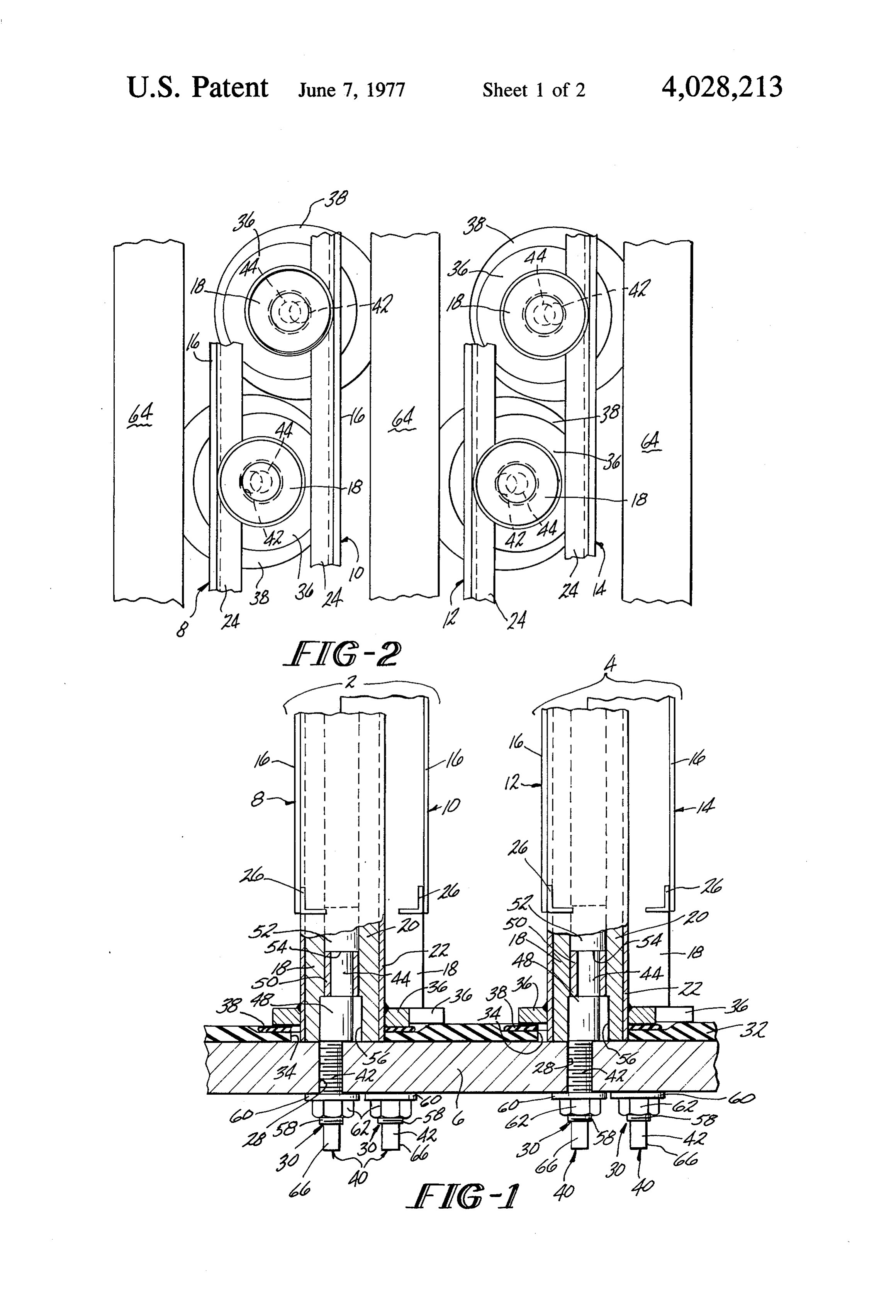
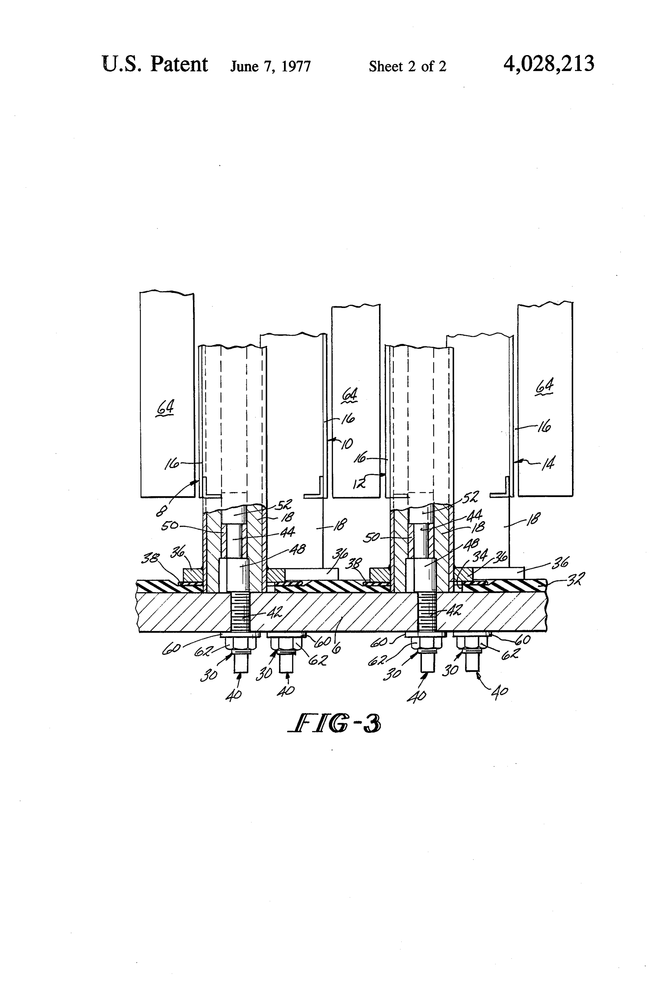
would cause operational problems due to the mixing of DESCRIPTION OF THE DRAWINGS the anode and cathodic products. In the case where the diaphragm is asbestos, scraping might also cause asbes The present invention will be more readily under tos particles to break loose from the diaphragm, which stood by reference to the following detailed description is also undesirable. Therefore, the anode-cathode gap 50 and to the accompanying drawings in which: must be wide enough to permit assembly of the cell. FIG. 1 is a simplified transverse view, partially in However, it is desirable to keep the anode-cathode gap section through an electrolytic cell showing the im small since the resistance of the electrolyte in the gap proved anode mounting structure of the present inven to the passage of electrolyzing current raises signifi tion with the cell can and cathodes removed for clarifi cantly the operating voltage of the cells. Thus, the 55 cation;
wider the gap, the greater the energy consumption and FIG. 2 is a simplified plan view of the structure shown the more costly the cell is to operate. The space re in FIG. 1 and showing the cathode in place; and quired to permit proper assembly of the components of FIG. 3 is a view similar to FIG. 1, but showing the the cell is usually greater than the optimum anode cathode in place and the anodes adjusted so that the cathode gap which results in the most efficient opera 60 anode-cathode gap is the smallest. tion of the cell. DETALED DESCRIPTION In order to overcome the above problem, it has been proposed previously in U.S. Pat. No. 3,796,648, issued Referring to the drawings and particularly to FIG. 1, Mar. 12, 1974, to Conner, Jr., et al, to attach the anode there is shown two anodes 2 and 4 attached to an anode post to the base plate by having a threaded stud portion 65 mounting plate 6. The anode 2 comprises two anode thereof protrude through an enlarged hole in the base sections 8 and 10 which are capable of lateral move plate. When the nuts are untightened, the anodes can ment with respect to the mounting plate 6 relative to be moved laterally with respect to the base plate either each other. The anode 4 comprises two anode sections
Page 5
12 and 14 which are also capable of lateral movement washer 36 will engage the gasket 38 so that the lining with respect to the mounting plate 6 relative to each 32 and the gasket 38 are compressed into tight sealing other. Each anode section 8, 10, 12, and 14 includes a relationship to seal the holes 28 in the mounting plate metal surface 16 and an anode mounting post 18 con 6.
nected to the metal surface 16 by any suitable tech Each anode attaching means 30 includes a crank nique such as welding or the like. Each anode mounting member 40 having a crank shaft portion 42 extending post 18 is attached to the anode mounting plate 6 and through an associated hole 28 in the anode mounting held in position such that the anode sections 8, 10, 12, plate 6. The other end of the crank member 40 includes and 14 extend generally perpendicular to the base plate a shaft portion 44 having an axis parallel to, but offset 6. O with respect to the axis of the crank shaft portion 42 Each anode mounting post 18 may be in the form of and which is mounted in the bore 46 of a post 18. The a generally tubular, elongated member. The post 18 axis of portion 44 is coincident with the axis of the bore may be fabricated from a core 20 clad with an exterior 46. Portions 42 and 44 may be interconnected by any sheet 22. Usually core 20 is constructed of aluminum, suitable means depending upon how the crank member copper, iron, steel and the like and is clad with an 15 40 is fabricated. As shown in the drawings, portions 42 exterior sheet 22 of a corrosion resistant metal such as and 44 are interconnected by an intermediate cylindri titanium. Although titanium is generally utilized for the cal portion 48 which has one edge coincident with the sheet 22, other suitable metals include tantalum, co outer edge of the crank shaft portion 42 and its oppo lumbium, and zirconium. site edge coincident with the outer edge of portion 44. Each metal surface 16 may be a solid sheet or mesh 20 Other arrangements may be used as long as the axis of con.prised of a titanium base coated with at least one the crank shaft portion 42 is offset with respect to the metal and/or metal oxide of a platinum group metal axis of portion 44.
such as platinum or ruthenium oxide. However, other Surrounding portion 44 of the crank member 40 is a suitable metals, metal oxides, and mixtures thereof split retaining ring 50 preferably fabricated from cop useful as these metal surfaces are well known in the art. 25 per or other suitable electrically conductive material. Each metal surface 16 may be stiffened through the use The ring 50 acts as a bearing surface for portion 44 and of upper and lower elongated angle brackets 24 and 26 also as the axial connection between the post 18 and which extend substantially the entire width of the the crank member 40. The crank member 40 termi anode section. The brackets 24 and 26 may be fabri nates in an enlarged head portion 52 having a diameter cated from titanium or other suitable material. Each of 30 substantially equal to the diameter of the bore 46 of the the metal surfaces 16 are attached to a mounting post anode mounting post 18 and having a shoulder 54 for 18 by any suitable electrically conductive attaching axially engaging the end of ring 50. means such as welding. The upper end of the crank member 40 is inserted The anode mounting plate 6 is preferably the base of into the bore 46 of the anode mounting post 18 with the the electrolytic cell. As such it may be constructed 35 split retaining ring 50 being press-fitted within the bore from an electrically conductive metal such as alumi 46 to provide tight connection therewith. Other meth num, copper, iron, steel, alloys of at least one of these ods of assembling the ring 50 within the bore 46 of the metals, and the like. In such a case, the anode mounting post 18 may be used so long as a tight connection is plate 6 may serve as the current conductor to the an obtained between the ring 50 and post 18 in at least the odes 2 and 4. 40 axial direction. The lower end of each post 18 is pro The anode mounting plate 6 is provided with a plural vided with a counter-bore 56 to receive the intermedi ity of holes 28 through which anode attaching means ate portion 48 of the crank member 40. 30 for the anode mounting posts 14 extend. The anode After a crank member 40 has been inserted into the mounting plate 6 is preferably covered with a lining 32 lower end of an anode mounting post 18, the crank which isolates the base from the anolyte and helps seal 45 shaft portion 42 may be inserted through a gasket 38, a the holes 28 in the base plate 6. The lining preferably hole 34 in the lining 32 and one of the holes 28 in the should be non-metallic, non-conductive, and corrosion mounting plate 6. Each crank shaft portion 42 may resistant. Some suitable materials are hard rubber, include a threaded section 58 for the reception of a polyethylene, chlorinated polyvinyl chloride, neo washer 60 and a threaded nut member 62. When the prene, polyproplyene, acrylonitrile-butadiene-styrene 50 nut member 62 is tightened, the shoulder 54 of the polymers (ABS), with or without fiberglass reinforce head portion 52 of the crank member 40 will be pulled ment fillers, polymerized fluorinated ethylene, polyes down against the split retaining ring 50. Because of the ter, mixtures thereof and the like. Hard rubber is pref fact that the ring 50 is axially secured in the post 18, erably used as the lining 32. The lining 32 is provided tightening of the nut member 62 will also draw the end with holes 34 coaxial with each of the holes 28 in the 55 of the post 18 tight against the mounting plate 6 so that mounting plate 6 and of such size that each of the posts a good electrical connection will be maintained be 18 can move freely therein. tween them. In addition, when the nut member 62 is Each anode mounting post 18 is provided with a tightened against the washer 60 and base plate 6, the washer 36 which is welded or otherwise suitably at washer member 36 attached to the post 18 will be tached thereto to provide a permanent connection 60 drawn against the gasket 38 which in turn is drawn therebetween. A relatively soft rubber gasket 38, hav against lining 32 to provide good sealing relationship ing an aperture 39 therein of a diameter substantially therebetween.
equal to that of a hole 34 in the lining 32, surrounds With the crank members 40 associated with anode each post 18 and is interposed between the washer 36 sections 8 and 12 positioned as shown in FIG. 1, it may and the hard rubber lining 32. The bottom surface of 65 be seen that the anode sections 8 and 12 are positioned each washer 36 is spaced from the end of its anode in their righthand-most position as viewed in that fig mounting post 18 a suitable distance so that when the ure. As shown, the axis of portion 44 is offset to the post 18 is pulled down against the base plate 6, the right with respect to the axis of crank shaft portion 42.
Page 6
Each of the crank members 40 which is associated with only one anode section be movable relative to the base anode sections 10 and 14 have the axis of its portion 44 plate and the other attached in an unmovable manner. offset to the left with respect to the axis of the crank In addition, the above described attaching means 30 shaft portion 42 so that the anode sections 10 and 14 may also be used in connection with anodes having are positioned in their lefthand-most position as viewed 5 both metal surfaces attached to the same posts. In any in F.G. 1. given application, it is to be understood that a given In this position, anode sections 8 and 10 of anode 2 anode or anode section-may, because of its length, have will be positioned closest together as will the anode associated with it more than one anode mounting post sections 12 and 14 of anode 4. The space or gap be 18 each of which could have a corresponding attaching tween facing anode sections 10 and 12 of adjacent 10 means 30.
anodes will be the greatest. With the anodes arranged The anode attaching means of the present invention in this manner, cathodes 64 (see FIG. 2) may be posi may be used in electrolytic cells of the type having at tioned between facing anode sections. As the space least one anode and at least one foraminous cathode. between the opposing anode sections of adjacent an Such cells may be of many different types and designs odes is relatively large, there is less likelihood of scrap 15 and may or may not include a diaphragm or membrane ing or damaging the cathode or its attached diaphragm in the anode-cathode gap. For example, the present during assembly. invention may be used in a cell used for the electrolysis When the cathodes 64 are in place, the anodes 2 and of alkali metal chloride solutions, including not only 4 may be adjusted so that the gap between an anode sodium chloride but also potassium chloride, lithium section and its associated cathode is brought to the 20 chloride, rubidium chloride and cesium chloride. In the minimal practical distance. This is accomplished by electrolysis using a diaphragm covering the foraminous loosening the nut members 62. With a nut member 60 cathode, caustic, chlorine and hydrogen are produced. loosened, each crank shaft portion 42 may be rotated Using certain modifications and changes in the method about its axis. To facilitate this, the free end of the of reacting, such as by removing the diaphragm or crankshaft portion 42 may be suitably machined to 25 further reacting the produced caustic and chlorine, provide a grasping portion 66 having a square cross alkali metal chlorates can also be produced. In some section for facilitating the grasping thereof by a wrench instances, when used for the production of alkali metal or other suitable torque-applying implement. chlorates, solutions containing both alkali metal chlo Upon rotation of the crankshaft portion 42, the axis rate and alkali metal chloride may be recirculated to of portion 42 which is coincident with the axis of the 30 the cell for further electrolysis. In addition, the inven anode mounting post 18 will revolve about the axis of tion may be utilized in a cell for the electrolysis of portion 42 until it is positioned on the opposite side hydrogen chloride by electrolyzing hydrogen chloride thereof. This movement of portion 42 carries with it the in combination with an alkali metal chloride. Thus, the anode mounting post 18 and its associated anode sec present invention is highly useful in these and many tion. 35 other aqueous electrolytic processes. Referring to FIGS. 1 and 2, rotation of the crank By virtue of the above described anode attaching shaft portion 42 of the crank members 40 associated means, it is possible to mount the anodes of an electro with anode sections 8 and 12 from the position shown lytic cell on an anode mounting plate in a manner in FIG. 1, will move the anode sections 8 and 12 to the which maximizes the distance between facing anode left moving them closer to their associated cathode. surfaces of adjacent anodes so that the cathodes can be Rotation of the crank shaft portion 42 of the crank easily inserted into place between the anodes. The members 40 associated with anode sections 10 and 14, anodes can be easily adjusted to decrease the gap be from the position shown in FIG. 1, will move the anode tween the anode surface and its respective cathode by sections 10 and 14 to the right as viewed in FIGS. 1 and imparting rotation to the connecting assembly. This 2 and narrow the gap between them and their asso 45 rotation results in positive movement being imparted to ciated cathodes. Maximum displacement of the anode the anodes.
posts takes place upon 180° rotation of the crank shaft What is claimed is:
portion 34 from its position shown in FIG. 1. FIG. 3 1. A multiple anode assembly for an electrolytic cell shows the anode after maximum displacement has of the type including an anode mounting plate, at least taken place. 50 one anode, and at least one foraminous cathode, said When the anode sections of the electrolytic cell are assembly comprising:
moved toward their associated cathodes a suitable dis a. at least one mounting means for each of said an tance to provide the properanode-cathode gap, the nut odes, said mounting means is a post, one end of members 54 may be re-tightened. The anode sections said post being held in electrical contact with said will then be held in proper spaced relationship with 55 anode mounting plate; and respect to the cathodes. b. attaching means for attaching at least some of said The maximum amount of lateral movement of any of mounting means to said anode mounting plate so the anode sections is twice the distance between the said anodes are maintained in a substantially per axis of the crank shaft portion 42 and portion 44 of the pendicular relationship thereto, said attaching crank. The crank shaft may be constructed to provide 60 means including a portion extending through said any reasonable amount of movement limited by practi anode mounting plate and adapted for rotation cal design considerations and construction of the elec therein for imparting lateral movement to said trolytic cell. mounting means with respect to said anode mount Although the above described preferred embodiment ing plate.
contemplates the use of an anode having two anode 65 2. The assembly of claim 1 wherein said attaching sections each of which can be moved relative to each means includes a crank member having a first portion other, other anode arrangements may also be used. For mounted for rotation about its axis in said anode example, in some instances it may be desirable that mounting plate and a second portion mounted in said
Page 7
mounting means, the axis of said second portion being in said mounting plate and adapted for rotation parallel to and offset with respect to the axis of said first therein whereby upon rotation thereof lateral portion. movement with respect to said mounting plate is 3. The assembly of claim 1 wherein said anode imparted to said anode section. mounting plate is the cell base plate and is an electrical 5 6. The assembly of claim 5 wherein said attaching conductor and said attaching means includes means for means includes a crank member having a first portion holding said mounting means in electrical contact with mounted for rotation about its axis in said anode said base plate. mounting plate and a second portion mounted in said 4. A multiple anode assembly for an electrolytic cell mounting means, the axis of said second portion being of the type including an anode mounting plate, at least 10 parallel to and offset with respect to the axis of said first one foraminous cathode, and a plurality of substantially portion.
parallel anodes, said anodes having at least two anode 7. The assembly of claim 6 wherein said anode sections, at least one of which is movable with respect mounting plate is electrically conductive and said at to the other, said assembly comprising:
a. at least one mounting means for each anode sec 15 taching means further includes means for holding said tion, said mounting means is a post, one end of said ing plate. means in electrical contact with said mount mounting post being held in electrical contact with said 8. The assembly of claim 7 wherein said means for anode mounting plate; and holding includes a sleeve mounted in said mounting b. attaching means for attaching at least one of said means and mounting means of at least one of the anode sec 20 engagementawith shoulder on said crank member for axial said sleeve.
tions to said anode mounting plate, said attaching means including a portion extending through said sealing the openingsofthrough 9. The assembly claim 7 further including means said mounting plate.
mounting plate and adapted for rotation therein whereby upon rotation thereof lateral movement conductive lining over said basefurther 10. The assembly of claim 9 plate, including a non said lining hav with respect to said mounting plate is imparted to ing an aperture coincident with each opening
through said anode section.
5. A multiple anode assembly for an electrolytic cell said mounting plate, said aperture being of a size at of the type including an anode mounting plate, at least least equal to the surface area covered by the move one foraminous cathode, a plurality of substantially ment of said mounting means upon rotation of said parallel anodes, said anodes having adjustable anode 30 crank member, a washer member connected to each sections, said assembly comprising: said mounting means, a gasket member about said a. at least one mounting means for each anode sec mounting means and interposed between said lining tion, said mounting means is a post, one end of said and said washer member, and means associated with post being held in electrical contact with said said attaching means for drawing said washer member anode mounting plate; and 35 toward said mounting plate for sealing engagement of b. attaching means for attaching each said mounting said gasket member with said lining and said washer means to said base plate, said attaching means member.
including a portion extending through an opening 2k xk is k >
Provenance
- Collection
- Cited prior art
- Original PDF
- patentimages.storage.googleapis.com →
- Filed
- 1976-02-09
- Pages
- 7
- Method
- pdftotext (the PDF's own text layer) + pdftoppm 300dpi page scans
- Source
- Google Patents bibliographic record
- Granted
- 1977-06-07
- Inventors
- James M. Ford; Olin Corp
- Transcribed from
- patentimages.storage.googleapis.com →