patent · US5858185
Electrolytic apparatus
12 January 1999
Page 1 — bibliographic record
United States Patent (19) 11 Patent Number: 5,858,185 Christian (45) Date of Patent: Jan. 12, 1999 54 ELECTROLYTIC APPARATUS 3.990,962 11/1976 Götz .................................... 204/272 X 4,175,026 11/1979 Houseman .............................. 204/272 75 Inventor: John Daniel Christian, Wellington, 4,457,816 7/1984 Galluzzo et al. 204/105 R New Zealand 5,082.544 1/1992 Willey et al. ........................... 204/270 5,450,822 9/1995 Cunningham ....................... 204/272 X 73 ASSignee: legs New Zealand Limited, New FOREIGN PATENT DOCUMENTS
21 Appl. No.: 702.707 961 125 6/1964 United Kingdom.
22 PCT Filed: Mar. 8, 1995 1278 591 6/1972 United Kingdom. 86 PCT No.: PCT/NZ95/00026 2 270 749 3/1994 United Kingdom. S371 Date: Dec. 5, 1996 Primary Examiner Donald R. Valentine Attorney, Agent, or Firm-Pravel, Hewitt & Kimball
S 102(e) Date: Dec. 5, 1996 57 ABSTRACT 87 PCT Pub. No.: WO95/24519 The invention is directed to a cell for an electrolytic appa PCT Pub. Date: Sep. 14, 1995 ratus which comprises a pressure vessel containing a Self contained electrode unit. The electrode unit has an inlet for 30 Foreign Application Priority Data the Supply of electrolyte and an outlet for liberated ad-mixed Mar. 8, 1994 NZ New Zealand........................... 260051 hydrogen and oxygen gas. The electrode unit further having plurality of Spaced-apart concentric cylindrical electrodes 51 Int. C. - - - - - - - - - - - - - - - - - - - - - - - - - - - - - - - - - - - - - - - - - - - - - - - - - - - - - - - - C25B 9/00 and a pair of internal end plates provided at each end of the
52 U.S. C. ... ... 204/272; 204/278 concentric cylinders. At least one of the internal end plates 58 Field of Search ..................................... 204/272, 270, includes the electrolyte inlet and/or gas outlet. The preSSure 204/277,278 vessel comprises a cylindrical outer shell having planar transverse end plates which are connected at or adjacent to 56) References Cited the opposed ends of the cylindrical outer Shell. The preSSure
liberated gas.
2.375,069 5/1945 Bennett et al. ........................... 62/135 3,964,991 6/1976 Sullins .................................... 204/275 20 Claims, 3 Drawing Sheets
Page 2
Drawing sheet — no readable text.
Page 3
Drawing sheet — no readable text.
Page 4
Drawing sheet — no readable text.
Page 5
ELECTROLYTIC APPARATUS Furthermore, it is an object of at least an aspect of the
BACKGROUND
invention to provide a gas drying apparatus which over comes many of the disadvantages of the prior art and (i) Field of the Invention provides advantages unknown So far. It is also an object of This invention relates to the provision of electrolytic the invention to provide the public with a useful choice. apparatus and, in particular, although not necessarily Solely, electrolytic apparatus Suitable for welding. (iv) SUMMARY OF THE INVENTION (ii) Description of the Prior Art Accordingly, in a first aspect, the invention may broadly Conventional electrolytic apparatuS has been made to be said to consist in a cell for electrolytic apparatus wherein manufacture hydrogen and oxygen from water. One use of Said cell is a pressure cell containing a plurality of concentric Such hydrogen oxygen production is in welding equipment cylindrical electrodes Spaced apart by insulators and at least to replace the convention oxyacetylene mixture for gas one end plate provided at an end of Said concentric cylinders welding. Many other uses of the hydrogen oxygen will be and including apertures to permit fluid and gas flow between apparent to those skilled in the art. However, the provision 15 Said cylinders, and wherein Said preSSure cell comprises a of welding equipment based on the hydrolysis of water into cylindrical Outer Shell having planar transverse end plates hydrogen and oxygen can have special problems. connected at or adjacent opposed ends of Said cylindrical Existing prior art hydrolysis equipment has included outer shell.
conventional horse shoe cells as well as cells utilising plates In a further aspect, the invention may broadly be said to within a generally rectangular cell and the use of membranes consist in a gas drying apparatus comprising a drying between the plates Such that the hydrogen and oxygen are chamber; an inlet valve into Said drying chamber wherein Separated within the cell. Such membranes often comprise Said drying chamber is of greater croSS Section than an Silk, polyester woven cloth or a variety of other plastic aperture of Said value and wherein Said drying chamber membranes between adjacent electrode plates that allow further includes a Stranded condensation Surface which will charge to transfer from one plate to another and yet inhibit 25 allow gas to pass through apertures between Strands of Said the free flow of gas bubbles within the solution. Surface and the Strands of the Surface providing a Surface The use of such cells allows the separation of the hydro area for the condensation of the water vapour. gen and oxygen from its point of formation and the hydrogen Other aspects of this invention which should be consid and oxygen may be maintained in Separate conduits through ered novel will become apparent from the following descrip out the apparatus until its necessary combination at the head tion.
of the welder or Similar apparatus.
The use of Such technology involves complex manufac (v) BRIEF DESCRIPTION OF THE DRAWINGS ture in the use of the impermeable membranes, a greater The invention will now be described with reference to the degree of maintenance and also less efficient gas production following drawings in which:
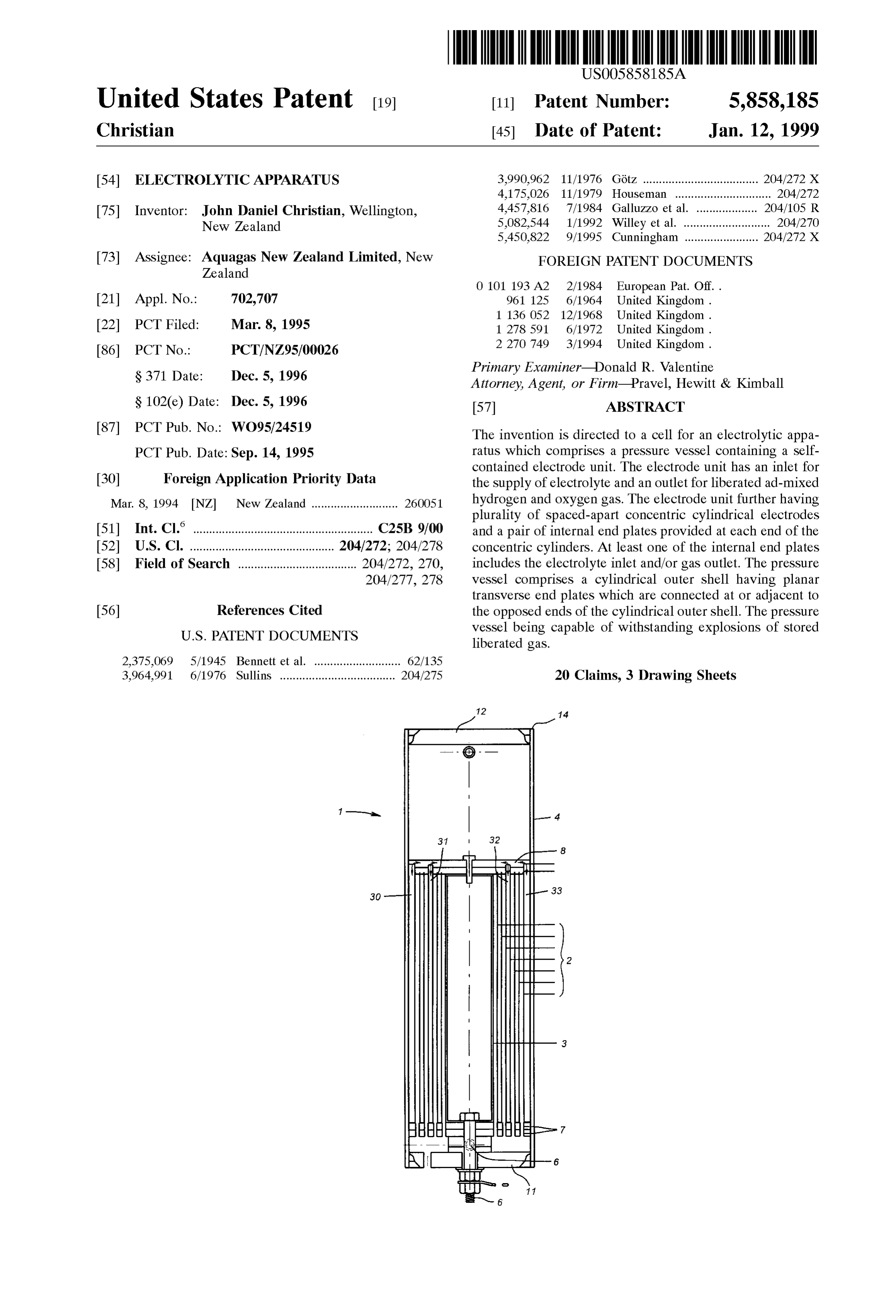
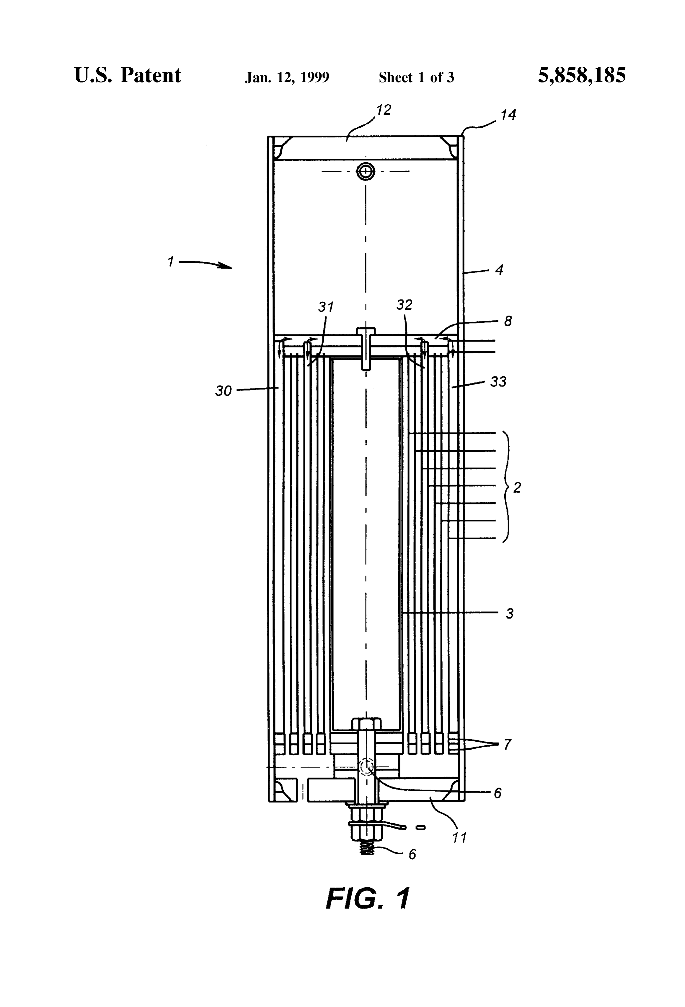
than other configurations. In particular, the use of concentric 35 FIG. 1 is a croSS Sectional elevation through a pressure cylindrical electrodes within a cell allows more efficient gas cell in accordance with one embodiment of this apparatus, production, however, there are manufacturing difficulties in FIG. 2 is a plan view of the pressure cell of FIG. 1; providing impermeable membranes or other Separators to avoid the production of a mixed hydrogen and oxygen gas D-D FIG. 3 is a croSS Sectional elevation through croSS Section within the cell. 40 of FIG. 2 and omitting the electrolytic cylinders for clarity;
Gas produced from concentric cylindrical electrodes may be used in its mixed form as produced or later Separated into FIG. 4 is a partial croSS Sectional elevation showing detail hydrogen and oxygen components. In either case, it is A of FIG. 3;
difficult to avoid the production of the mixed hydrogen and FIG. 5 is a partial cross sectional view of detail B of FIG. oxygen gas within the cell itself. Therefore, it is necessary 45 2, FIG.
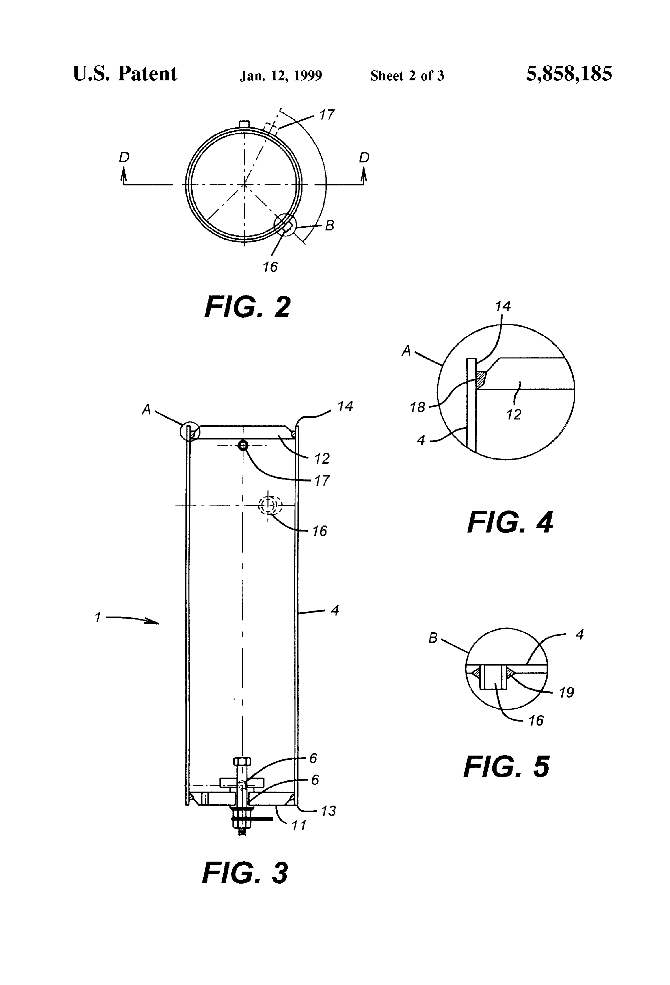
and 6 is a croSS Sectional view through a gas drying to incorporate adequate Safety measures against explosion of the Volatile hydrogen and oxygen mix within the cell should invention. in accordance with a further embodiment of this apparatus a fault cause ignition to occur within the cell.
A further problem encountered with Such welding appa (vi) DETAILED DESCRIPTION OF PREFERRED ratus is that the generation of hydrogen and oxygen by the 50 EMBODIMENTS hydrolysis process causes Some Saturated water vapour to
Referring to the drawings, leave the generating cells with the gases. This may typically comprises a pressure cell 1 containing one aspect of this invention be a value of Say three percent by Volume and in the case of an electrolytic appa combustion Such as is required with welding apparatus, the ratus in the form of a Series of concentric cylinders 2 nested Saturated water vapour may have the effect of reducing the 55 within each other. The cylinders 2 act as electrodes within flame temperature from 3000° C. to 2,500° C. The saturated the electrolytic cell and an electrolyte Such as potassium water vapour within the generated gas can also provide other hydroxide may be used in conjunction with the cylinders. problems Such as condensation in reticulation Systems and The inner most cylinder 3 and the outer most cylinder 4 may corrosion of Safety devices. act as the external electrodes for the apparatus. AS can be 60 seen in FIG. 1, the internal cylinder 3 is connected via (iii) OBJECT OF THE INVENTION connecting bolt 6 to the outside of the pressure cell to Therefore, it is an object of the present invention to provide this electrode with a connection point external of the provide a cell for the containment of an electrolytic cell preSSure cylinder.
which overcomes many of the disadvantages of the prior art When electrolytic apparatus of this type is used for the and provides advantages unknown So far. It is also an object 65 production of hydrogen and oxygen for Subsequent com of the invention to at least provide the public with a useful bustion as in welding apparatus or the like, Safety measures choice. must be incorporated to ensure that the apparatus does not
Page 6
explode from ignition within the electrolytic cell itself. In Steel components, Steel nickel plating may be provided most forms this would be through the provision of a number throughout. Alternatively, Some special grades of Stainless of Safety devices to prevent ignition within the electrolytic Steel may also Suit. The provision of the Steel nickel plating cell. In apparatus of the type of the present invention, this not only inhibits corrosion from the potassium hydroxide but may be difficult to achieve or expensive. The invention is 5 also aids in electrical conduction.
based on a different, and even reversed, approach to the problem. This approach is to prevent a fault ignition causing nonThe insulating components within the cell or any other metallic components used within or in conjunction with any damage rather than to prevent ignition itself to occur.
Therefore, the present invention Seeks to provide a pressure the cell may be constructed from high molecular weight polyethylene and, more preferably, ultra high molecular cell which can Safely contain ignition within the pressure weight polyethylene or nylon 11. cell itself. To this end, the pressure cell 1 is designed to withstand internal pressures in the order of 1000 PSIG even A concentric cell of this type is capable of high efficiency though the normal operating pressure of the cell itself is only gas generation. On a typical cell constructed in accordance in the order of 20 to 45 PSIG with a maximum working with this invention, an input of 34 volts and 250 amps has pressure of 50 PSIG. A cell designed to meet British 15 a theoretical gas production of 4 cubic metres per hour. This standard 5500 is Suitable. is on a specific plate area and other constraints determining For the electrolytic cell to operate efficiently, the concen the theoretical production of the cell. In practice, an actual tric cylinders are Self contained as a unit, and should be production of 3.6 cubic metres per hour has been possible. equally spaced apart by insulating members and provided Such an example of gas generation is repeated on a similar with end caps on the electrodes 7 and 8 which support the cell at different currents and it has been found that an input electrodes and inhibit, viz., increase the path length of, the current of 200 amps provides a theoretical production of 3.2 flow of fluid from within each cell between adjacent cylin cubic metres per hour and an actual production of 2.88 cubic ders to any cell other than the directly adjacent cell. This metres per hour.
may be provided by the provision of channels and baffles Thus it can be seen that the actual production from cells within the end caps 7 & 8. The channels 30–33 in FIG. 1 25 in this arrangement can be exceSS of 90 percent of the illustrate the longer path length between two pairs of elec theoretical gas production calculated on plate areas, etc. trodes with respect to the distance between adjacent elec In another aspect of this invention, a gas drying apparatus trodes. Similar channels are provided for other ones of the is provided as shown in FIG. 6. pairs, although cannot be seen in the particular croSS sectional view of FIG. 1. This arrangement provides the The hydrogen and oxygen mixture from the electrolysis is maximum flow path throughout the apparatus as a whole and provided through a Supply pipe or Similar 21 through an inlet prevent the short circuiting of flow between non adjacent valve or nozzle 22 to the drying chamber 23. The use of a cells. high Velocity increase in the gas via the Small aperture To provide Such an arrangement, it is necessary to provide provided in the valve 22 and the outlet to the much larger an outer pressure cell 1 which provides planar transverse end 35 chamber 23 will cause condensation of much of the water plates as opposed to the conventional dome shaped ends on Vapour contained within the gas Stream.
conventional preSSure cells. These end plates 11 and 12 may In addition, the drying chamber 23 can contain a Stranded be mounted adjacent ends 13 and 14 respectively of the outer condensation Surface 24 intermediate of the inlet 22 and the shell 4 of the pressure cell 1. outlet 25 from the drying chamber 23. This stranded con To accommodate the preSSures possible following igni 40 densation Surface 24 will provide further cooling and a tion within the pressure cell 1, the outer shell 4 may be Surface on which the heavy water molecules can collect and constructed from Schedule 20 Steel pipe and the end plates thereby provide further drying of the gas as it moves through 11 and 12 constructed from steel boiler plate such as 25 mm the chamber 23.
thick boiler plate or, preferably, at least a thickness of greater The stranded condensation surface 24 may be a fibrous than 20 mm. 45 artificial wool and a StainleSS Steel wool has been found to
As shown in FIGS. 2 and 3, the pressure cell must also be particularly Suitable. Amongst other advantages, the accommodate filler points 16 and other sockets 17 for inlets Stainless Steel wool will not corrode in the gas Stream and and outlets into the preSSure vessel itself. These must also also provides a function as a flame arrester as an additional accommodate the pressures exerted by ignition within the Safety point. Condensation collected within the drying cell to ensure that the Sockets themselves do not detach in 50 chamber 23 may be drained through the drain 26 to a Such a circumstance. conventional water collection tank 27. The water so col Referring specifically to FIG. 4, the end plates Such as end lected may then be returned through an outlet 28 to the plate 12 may be placed within the confines of the outer remainder of the apparatus for further electrolysis. casing 4 adjacent to the end 14. A welded connection 18 may In keeping with the electrolytic cells themselves, the be provided to connect the end plate 12 to the wall 4 of the 55 drying chamber 23 may comprise a pressure vessel con pressure cylinder 1. It has been found that a weld to structed to British standard 5500 to accommodate ignition of approximately half the depth of the end plate 12 will operate the gas within the cell. In this instance, the preSSure cell 23 Satisfactorily in maintaining a connection between the cyl may be of any convenient shape including a dome ended inder wall 4 and the end plate 12 even upon ignition within preSSure cell.
the pressure cell. 60 Thus it can be seen that a pressure cell for the housing of Referring to FIG. 5, heavy duty sockets to accommodate the electrolytic apparatus is provided which may conform to filling of the pressure vessel may also be provided with British standard 5500 and accommodate potential ignition welded connections 19 about the entire circumference of the within the pressure cell while providing planar transverse Socket 16 to provide a Secure connection between the Socket ends to the pressure cell for the easy accommodation of the 16 and the wall 4 of the pressure vessel 1. 65 concentric cylinders arranged as part of the cell apparatus. Within the electrolytic cell, the potassium hydroxide used Furthermore, a gas drying apparatus is provided to as an electrolyte is corrosive and to avoid degradation of the remove water vapour from the resultant gas Stream to
Page 7
S 6 improve the operation of the apparatus in its preferred 9. The cell of claim 8, wherein said stranded condensation intended use as a welding apparatus. Surface comprises a fibrous artificial wool. Where in the foregoing description, reference has been 10. The cell of claim 8, wherein said stranded condensa made to Specific components or integers of the invention tion Surface comprises Stainless Steel wool. having known equivalents, then Such equivalents are herein 11. The cell of claim 8, wherein said stranded condensa incorporated as if individually set forth. tion Surface additionally acts as a flame arrester. Although this invention has been described by way of 12. A cell for electrolytic apparatus comprising a pressure example and with reference to possible embodiments vessel, Said pressure vessel comprising: thereof, it is to be understood that modifications or improve a Self-contained electrode unit having an inlet for the ments may be made thereto without departing from the Supply of electrolyte and an outlet for liberated Scope or Spirit of the invention as defined in the appended admixed hydrogen and oxygen gas, Said electrode unit claims. having a plurality of Spaced-apart concentric cylindri I claim:
1. A cell for electrolytic apparatus comprising a pressure 15 cal electrodes and a pair of internal end plateS provided vessel, Said pressure vessel comprising: at each end of Said concentric cylindrical electrodes, at least one of Said internal end plates including Said a Self-contained electrode unit having an inlet for the electrolyte inlet and/or Said gas outlet and at least one Supply of electrolyte and an outlet for liberated of Said internal end plates including duct means for admixed hydrogen and oxygen gas, Said electrode unit communicating the electrolyte between Said concentric having a plurality of Spaced-apart concentric cylindri cylindrical electrodes by a circuitous path of a length cal electrodes and a pair of internal end plateS provided longer than between adjacent Said electrodes, and at each end of Said concentric cylindrical electrodes, at least one of Said internal end plates including Said a cylindrical Outer shell having planar transverse end electrolyte inlet and/or said gas outlet, and plates connected at or adjacent opposed ends of Said a cylindrical outer shell having planar transverse end 25 cylindrical outer shell, Said cylindrical outer shell and plates connected at or adjacent opposed ends of Said Said transverse end plates are made from Steel, Said cylindrical outer shell, Said preSSure vessel capable of preSSure vessel capable of withstanding explosions of withstanding explosions of the liberated gas Stored the liberated gas stored therewithin. therewithin. 13. The cell of claim 12, wherein said transverse end 2. The cell of claim 1, wherein at least one of said internal plates are positioned slightly within Said outer shell and end plates includes duct means for communicating the welded into connection with said outer shell. electrolyte between Said concentric cylindrical electrodes by 14. The cell of claim 13, wherein said cylindrical outer a circuitous path of a length longer than between adjacent shell comprises a length of Schedule 20 Steel pipe. Said electrodes. 15. The cell of claim 14, wherein said transverse end 3. The cell of claim 1, wherein said cylindrical outer shell 35 plates comprise Steel plate of a thickness greater than or and Said transverse end plates are made from Steel. equal to 20 mm.
4. The cell of claim 3, wherein said transverse end plates 16. The cell of claim 15, wherein said transverse end are positioned slightly within Said outer shell and welded plates are welded to Said outer Shell to a depth of Substan into connection with Said outer shell. tially half the thickness of Said transverse end plate. 5. The cell of claim 4, wherein said cylindrical outer shell 40 17. The cell of claim 12, further comprising a cell port and comprises a length of Schedule 20 Steel pipe. a gas drying apparatus receiving the Stored liberated gas 6. The cell of claim 5, wherein said transverse end plates from Said cell port, Said gas drying apparatus comprising: comprise Steel plate of a thickness greater than or equal to a drying chamber;
7. The cell of claim 6, wherein said transverse end plates 45 an havinginlet valve into Said drying chamber, Said inlet valve an aperture;
are welded to said outer shell to a depth of Substantially half wherein Said drying chamber is of greater croSS Section the thickness of Said transverse end plate. than Said inlet valve aperture, and 8. The cell of claim 1, further comprising a cell port and a gas drying apparatus receiving the Stored liberated gas a Stranded condensation Surface having openings from Said cell port, Said gas drying apparatus comprising: 50 therethrough, Said Stranded condensation Surface a drying chamber; allowing gas to pass through Said openings and pro an inlet Valve into Said drying chamber, Said inlet valve viding a Surface area for the condensation of water Vapor.
having an aperture; 18. The cell of claim 17, wherein said stranded conden wherein Said drying chamber is of greater croSS Section 55 sation Surface comprises a fibrous artificial wool. than Said inlet valve aperture; and 19. The cell of claim 17, wherein said stranded conden a Stranded condensation Surface having openings sation Surface comprises StainleSS Steel wool.
therethrough, Said Stranded condensation Surface 20. The cell of claim 17, wherein said stranded conden allowing gas to pass through Said openings and pro sation Surface additionally acts as a flame arrester. Viding a Surface area for the condensation of water
Vapor. k k k k k
Provenance
- Collection
- Cited prior art
- Original PDF
- patentimages.storage.googleapis.com →
- Filed
- 1995-03-08
- Pages
- 7
- Method
- pdftotext (the PDF's own text layer) + pdftoppm 300dpi page scans
- Source
- Google Patents bibliographic record
- Granted
- 1999-01-12
- Inventors
- John Daniel Christian; Aquagas New Zealand Ltd
- Transcribed from
- patentimages.storage.googleapis.com →