patent · US4023545
Energy means for internal combustion engines
17 May 1977
Page 1 — bibliographic record
United States Patent (19) 11 4,023,545 Mosher et al. (45) May 17, 1977 54 ENERGY MEANS FOR INTERNAL 3,829,367 8/1974 Raviv ................................. 204/129 COMBUSTON ENGINES FOREIGN PATENTS ORAPPLICATIONS 76 Inventors: Edward G. Mosher, 2462 Transit 1,213,641 4/1960 France ........................ 123/DIG. 12 Ave., Anaheim, Calif. 92804; John
T. Webster, 2436 Greenleaf Ave., Primary Examiner-Wendell E. Burns
Anaheim, Calif. 928O1 Assistant Examiner-David D. Reynolds 22 Filed: Jan. 24, 1975 Attorney, Agent, or Firm-Limbach, Limbach & Sutton
(21) Appl. No.: 543,667 A gas generating system for use with internal combus (52) U.S.C. ............................... 123/119 E; 123/3; tion engines, to afford hydrogen gas and oxygen gas to 123/DIG. 12; 204/129 be intermixed with the fuel for the engine.
I51) int. Cl”...................................... FO2M 27/00 It comprises an electrolysis unit which is energized by 58 Field of Search ................ 123/DIG. 12, 119 E, the existing electrical system normally associated with 123/3; 204/129, 278, 293 an internal combustion engine, such unit utilizing dis 56 References Cited tilled water and Sodium Hydroxide as the electrolyte. UNITED STATES PATENTS The system further includes means for conducting am bient air into the electrolysis unit for agitating or mix 1876,879 9/1932 Drabold ...................... 123/DIG. 12 ing the electrolyte and removing the gases that accu 2,384,463 9/1945 Gunn et al. ... 123/DIG. 12 mulate on the anode and cathode. The unit comprises 2,509,498 5/1950 Heyl ......... 123/DIG. 12 a stainless steel tank as well as stainless steel anode and 2,588,450 3/1952 Zadra ................................ 204/293 cathode members.
3,459.953 8/1969 Hughes et al. ..................... 204/129 4 Claims, 5 Drawing Figures
Avayaomy sysya M7
Page 2
Drawing sheet — no readable text.
Page 3
Drawing sheet — no readable text.
Page 4
Drawing sheet — no readable text.
Page 5
specific embodiments when read in connection with
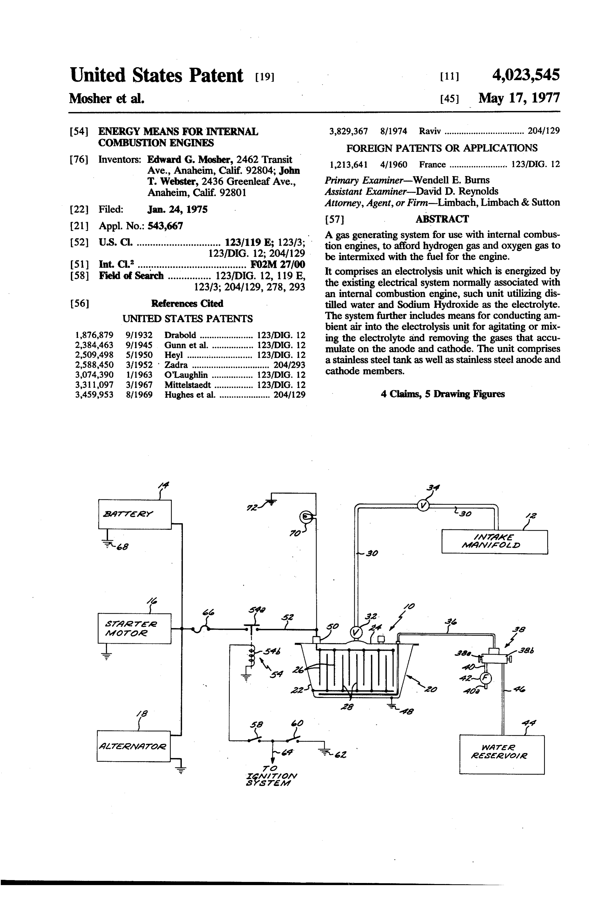
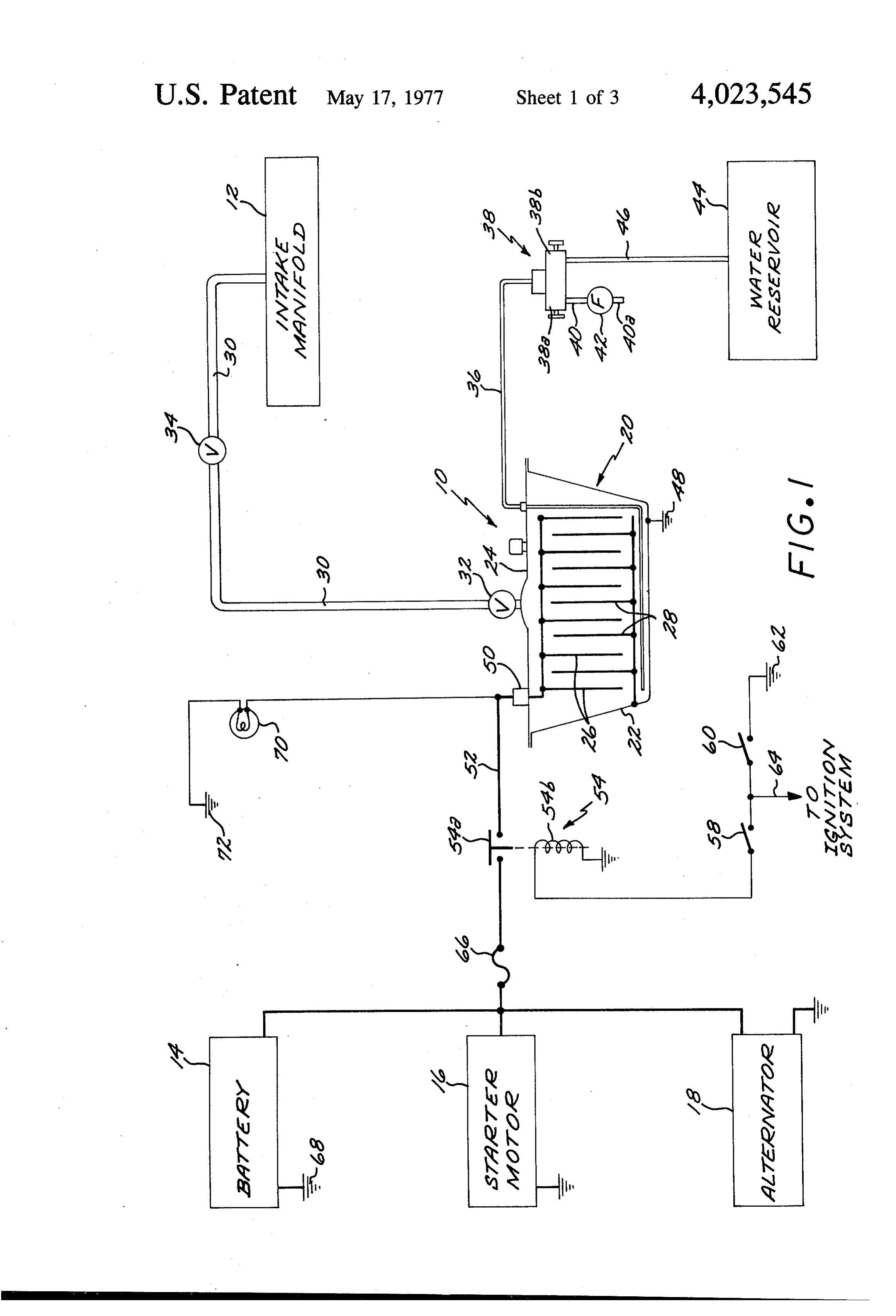
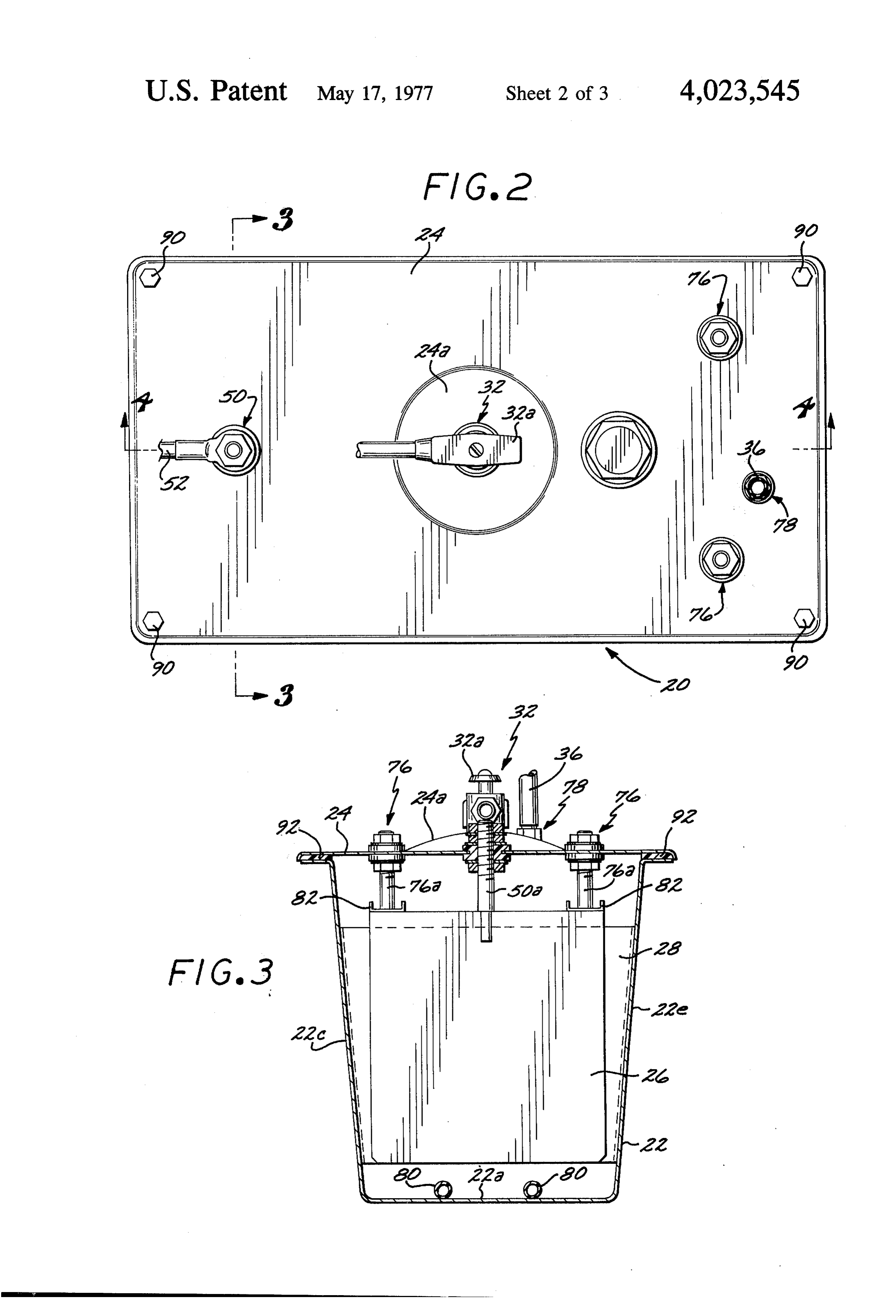
ENERGY MEANS FOR INTERNAL COMBUSTON the accompanying drawings, in which: ENGINES FIG. 1 is a schematic showing of a system according to the present invention;
The present invention relates generally to auxiliary 5 FIG. 2 is a top plan view of the electrolysis unit of the systems for internal combustion engines, and more subject system;
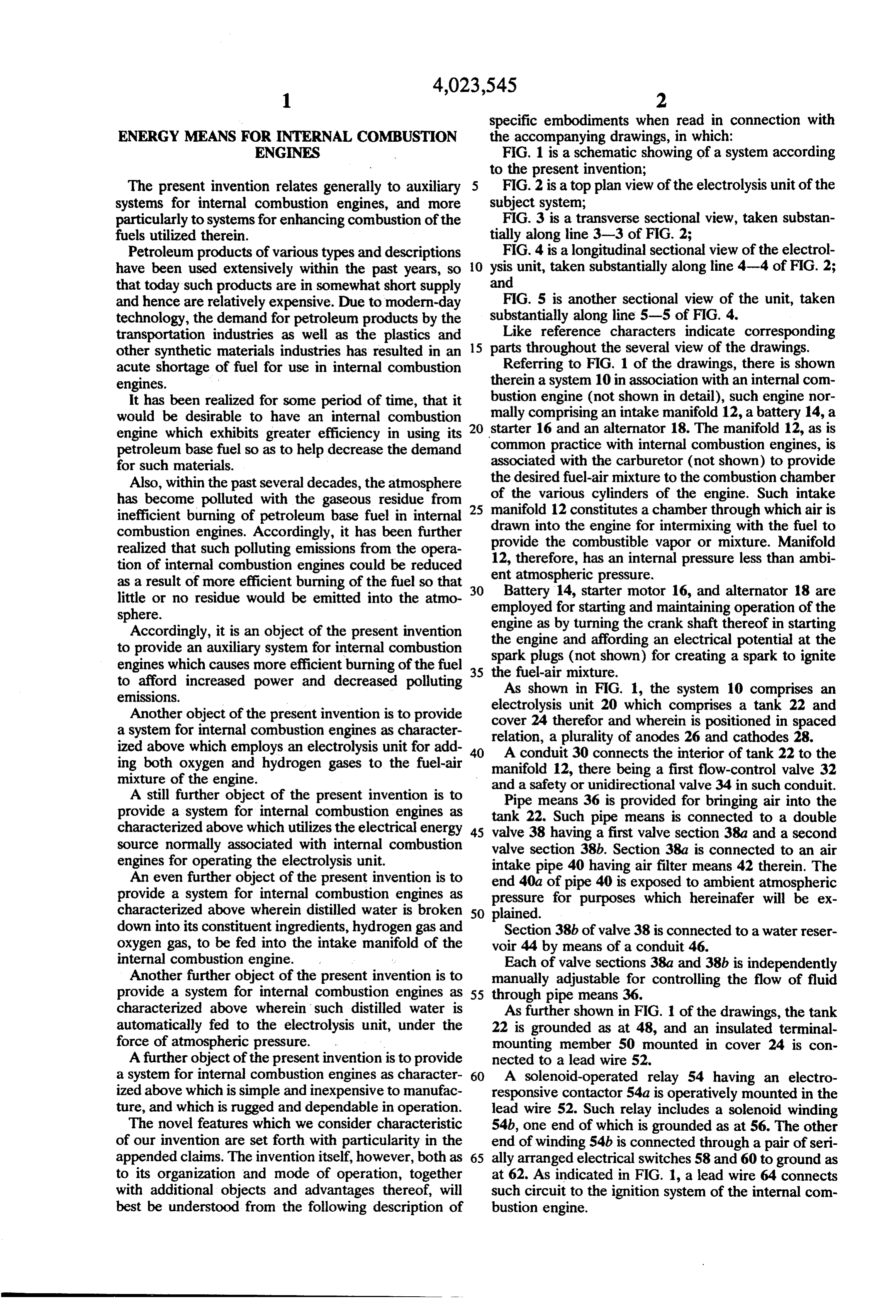
particularly to systems for enhancing combustion of the FIG. 3 is a transverse sectional view, taken substan fuels utilized therein. tially along line 3-3 of FIG. 2; Petroleum products of various types and descriptions FIG. 4 is a longitudinal sectional view of the electrol have been used extensively within the past years, so O ysis unit, taken substantially along line 4-4 of FIG. 2; that today such products are in somewhat short supply and and hence are relatively expensive. Due to modern-day F.G. 5 is another sectional view of the unit, taken technology, the demand for petroleum products by the substantially along line 5-5 of FIG. 4. transportation industries as well as the plastics and Like reference characters indicate corresponding other synthetic materials industries has resulted in an 15 parts throughout the several view of the drawings. acute shortage of fuel for use in internal combustion Referring to FIG. 1 of the drawings, there is shown engines. therein a system 10 in association with an internal com It has been realized for some period of time, that it bustion engine (not shown in detail), such engine nor mally comprising an intake manifold 12, a battery 14, a would be desirable to have an internal combustion engine which exhibits greater efficiency in using its 20 starter 16 and an alternator 18. The manifold 12, as is petroleum base fuel so as to help decrease the demand common practice with internal combustion engines, is for such materials. associated with the carburetor (not shown) to provide the
Also, within the past several decades, the atmosphere of the desired fuel-air mixture to the combustion chamber has become polluted with the gaseous residue from 25 manifoldvarious 12 cylinders of the engine. Such intake constitutes a chamber through which air is inefficient burning of petroleum base fuel in internal drawn into the engine for intermixing with the fuel to combustion engines. Accordingly, it has been further provide the combustible vapor or mixture. Manifold realized that such polluting emissions from the opera 12, therefore, has an internal pressure less than ambi tion of internal combustion engines could be reduced ent atmospheric pressure.
as a result of more efficient burning of the fuel so that 30 Battery 14, starter motor 16, and alternator 18 are little or no residue would be emitted into the atmo sphere. employed for starting and maintaining operation of the Accordingly, it is an object of the present invention engine as by turning the crank shaft thereof in starting to provide an auxiliary system for internal combustion spark plugsand the engine (not affording an electrical potential at the shown) for creating a spark to ignite engines which causes more efficient burning of the fuel 35 the fuel-air mixture.
to afford increased power and decreased polluting As shown in FIG. 1, the system 10 comprises an emissions.
electrolysis
Another object of the present invention is to provide cover 24 therefor unit 20 which comprises a tank 22 and a system for internal combustion engines as character relation, a pluralityand of wherein is positioned in spaced anodes 26 and cathodes 28.
ized above which employs an electrolysis unit for add 40 A conduit 30 connects the interior of tank 22 to the ing both oxygen and hydrogen gases to the fuel-air manifold 12, there being a first flow-control valve 32 mixture of the engine. and a safety or unidirectional valve 34 in such conduit. A still further object of the present invention is to provide a system for internal combustion engines as tank 22. Such pipe means is connected to ainto Pipe means 36 is provided for bringing air the double characterized above which utilizes the electrical energy 45 valve 38 having a first valve section 38a and a second source normally associated with internal combustion valve section 38b. Section 38a is connected to an air engines for operating the electrolysis unit. intake pipe 40 having air filter means 42 therein. The An even further object of the present invention is to end 4.0a of pipe 40 is exposed to ambient atmospheric provide a system for internal combustion engines as pressure for purposes which hereinafer will be ex characterized above wherein distilled water is broken 50 plained.
down into its constituent ingredients, hydrogen gas and Section 38b of valve 38 is connected to a water reser oxygen gas, to be fed into the intake manifold of the voir 44 by means of a conduit 46.
internal combustion engine. , Each of valve sections 38a and 38b is independently Another further object of the present invention is to manually adjustable for controlling the flow of fluid provide a system for internal combustion engines as 55 through pipe means 36.
characterized above wherein such distilled water is As further shown in FIG. 1 of the drawings, the tank automatically fed to the electrolysis unit, under the 22 is grounded as at 48, and an insulated terminal force of atmospheric pressure. mounting member 50 mounted in cover 24 is con A further object of the present invention is to provide nected to a lead wire 52.
a system for internal combustion engines as character 60 A solenoid-operated relay 54 having an electro ized above which is simple and inexpensive to manufac responsive contactor 54a is operatively mounted in the ture, and which is rugged and dependable in operation. lead wire 52. Such relay includes a solenoid winding The novel features which we consider characteristic 54b, one end of which is grounded as at 56. The other of our invention are set forth with particularity in the end of winding 54b is connected through a pair of seri appended claims. The invention itself, however, both as 65 ally arranged electrical switches 58 and 60 to ground as to its organization and mode of operation, together at 62. As indicated in FIG. 1, a lead wire 64 connects with additional objects and advantages thereof, will such circuit to the ignition system of the internal com best be understood from the following description of bustion engine.
Page 6
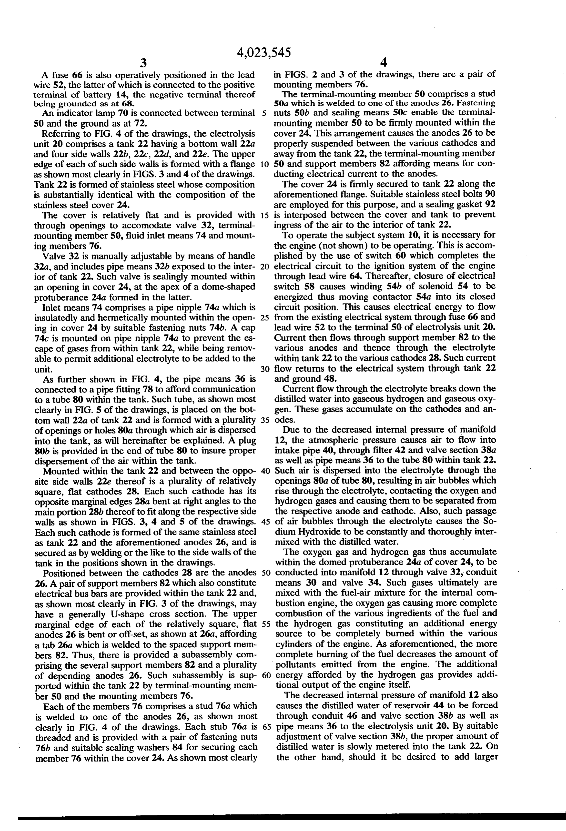
A fuse 66 is also operatively positioned in the lead in FIGS. 2 and 3 of the drawings, there are a pair of wire 52, the latter of which is connected to the positive mounting members 76.
terminal of battery 14, the negative terminal thereof The terminal-mounting member 50 comprises a stud being grounded as at 68. 50a which is welded to one of the anodes 26. Fastening An indicator lamp 70 is connected between terminal nuts 50b and sealing means 50c enable the terminal 50 and the ground as at 72. mounting member 50 to be firmly mounted within the Referring to FIG. 4 of the drawings, the electrolysis cover 24. This arrangement causes the anodes 26 to be unit 20 comprises a tank 22 having a bottom wall 22a properly suspended between the various cathodes and and four side walls 22b, 22c, 22d, and 22e. The upper away from the tank 22, the terminal-mounting member edge of each of such side walls is formed with a flange 10 50 and support members 82 affording means for con as shown most clearly in FIGS. 3 and 4 of the drawings. ducting electrical current to the anodes. Tank 22 is formed of stainless steel whose composition The cover 24 is firmly secured to tank 22 along the is substantially identical with the composition of the aforementioned flange. Suitable stainless steel bolts 90 stainless steel cover 24. are employed for this purpose, and a sealing gasket 92 The cover is relatively flat and is provided with 15 is interposed between the cover and tank to prevent through openings to accomodate valve 32, terminal ingress of the air to the interior of tank 22. mounting member 50, fluid inlet means 74 and mount To operate the subject system 10, it is necessary for ing members 76. the engine (not shown) to be operating. This is accom Valve 32 is manually adjustable by means of handle plished by the use of switch 60 which completes the 32a, and includes pipe means 32b exposed to the inter 20 electrical circuit to the ignition system of the engine ior of tank 22. Such valve is sealingly mounted within through lead wire 64. Thereafter, closure of electrical an opening in cover 24, at the apex of a dome-shaped switch 58 causes winding 54b of solenoid 54 to be protuberance 24a formed in the latter. energized thus moving contactor 54a into its closed Inlet means 74 comprises a pipe nipple 74a which is circuit position. This causes electrical energy to flow insulatedly and hermetically mounted within the open 25 from the existing electrical system through fuse 66 and ing in cover 24 by suitable fastening nuts 74b. A cap lead wire 52 to the terminal 50 of electrolysis unit 20. 74c is mounted on pipe nipple 74a to prevent the es Current then flows through support member 82 to the cape of gases from within tank 22, while being remov various anodes and thence through the electrolyte able to permit additional electrolyte to be added to the within tank 22 to the various cathodes 28. Such current unit. 30 flow returns to the electrical system through tank 22 As further shown in FIG. 4, the pipe means 36 is and ground 48.
connected to a pipe fitting 78 to afford communication Current flow through the electrolyte breaks down the to a tube 80 within the tank. Such tube, as shown most distilled water into gaseous hydrogen and gaseous oxy clearly in FIG. 5 of the drawings, is placed on the bot gen. These gases accumulate on the cathodes and an tom wall 22a of tank 22 and is formed with a plurality 35 odes.
of openings or holes 80a through which air is dispersed Due to the decreased internal pressure of manifold into the tank, as will hereinafter be explained. A plug 12, the atmospheric pressure causes air to flow into 80b is provided in the end of tube 80 to insure proper intake pipe 40, through filter 42 and valve section 38a dispersement of the air within the tank. as well as pipe means 36 to the tube 80 within tank 22. Mounted within the tank 22 and between the oppo 40 Such air is dispersed into the electrolyte through the site side walls 22e thereof is a plurality of relatively openings 80a of tube 80, resulting in air bubbles which square, flat cathodes. 28. Each such cathode has its rise through the electrolyte, contacting the oxygen and opposite marginal edges 28a bent at right angles to the hydrogen gases and causing them to be separated from main portion 28b thereof to fit along the respective side the respective anode and cathode. Also, such passage walls as shown in FIGS. 3, 4 and 5 of the drawings. 45 of air bubbles through the electrolyte causes the So Each such cathode is formed of the same stainless steel dium Hydroxide to be constantly and thoroughly inter as tank 22 and the aforementioned anodes 26, and is mixed with the distilled water.
secured as by welding or the like to the side walls of the The oxygen gas and hydrogen gas thus accumulate tank in the positions shown in the drawings. within the domed protuberance 24a of cover 24, to be Positioned between the cathodes 28 are the anodes 50 conducted into manifold 12 through valve 32, conduit 26. A pair of support members 82 which also constitute means 30 and valve 34. Such gases ultimately are electrical bus bars are provided within the tank 22 and, mixed with the fuel-air mixture for the internal com as shown most clearly in FIG. 3 of the drawings, may bustion engine, the oxygen gas causing more complete have a generally U-shape cross section. The upper combustion of the various ingredients of the fuel and marginal edge of each of the relatively square, flat 55 the hydrogen gas constituting an additional energy anodes 26 is bent or off-set, as shown at 26a, affording source to be completely burned within the various a tab 26a which is welded to the spaced support mem cylinders of the engine. As aforementioned, the more bers 82. Thus, there is provided a subassembly com complete burning of the fuel decreases the amount of prising the several support members 82 and a plurality pollutants emitted from the engine. The additional of depending anodes 26. Such subassembly is sup 60 energy afforded by the hydrogen gas provides addi ported within the tank 22 by terminal-mounting mem tional output of the engine itself.
ber 50 and the mounting members 76. The decreased internal pressure of manifold 12 also Each of the members 76 comprises a stud 76a which causes the distilled water of reservoir 44 to be forced is welded to one of the anodes 26, as shown most through conduit 46 and valve section 38b as well as clearly in FIG. 4 of the drawings. Each stub 76a is 65 pipe means 36 to the electrolysis unit 20. By suitable threaded and is provided with a pair of fastening nuts adjustment of valve section 38b, the proper amount of 76b and suitable sealing washers 84 for securing each distilled water is slowly metered into the tank 22. On member 76 within the cover 24. As shown most clearly the other hand, should it be desired to add larger
Page 7
amounts of distilled water to the unit, it is a simple said tank internally thereof, said cathode and said matter to remove cap 74c from pipe nipple 74a to tank being connected to the negative side of said enable such distilled water to be poured directly into source of electrical energy, and at least one anode the tank. - placed internally of said tank and spaced from Indicator lamp 70 is energized from the electrical contact with said tank and said cathode and con system whenever the contactor 54a is in closed circuit nected to the positive side of said source of electri position. This affords a visual indication of operation of cal energy, said tank being substantially filled with the unit. a solution of electrolyte and water, whereby appli In the event of an overload condition such that an cation of said electrical energy to said anode and to excessive amount of electrical current is drawn from 10 said cathode may cause generation of hydrogen gas the electrical system, the fuse 66 will respond to shut and oxygen gas from the water, down the entire unit. air conduit means extending into said tank beneath It is thus seen that the present invention provides a both said anode and said cathode such that bubbles system for internal combustion engines whereby more of air from said cathode may float upwardly imme complete combustion of the fuel takes place and thus 15 diately adjacent said anode and said cathode to cleaner operation of the engine results. Also the subject assist in removing said generated gases from said system provides more efficient operation of the engine anodeand said cathode; and by adding additional fuel to be burned. gas conduit means interconnecting said tank and said Although we have shown and described certain spe cific embodiments of our invention, we are well aware 20 and oxygen gases to saidtomanifold. engine intake manifold conduct said hydrogen that many modifications thereof are possible. 2. Energy means according to claim 1 wherein said We claim: cathode and said anode are formed of stainless steel. 1. Energy means for use with an internal combustion 3. Energy means according to claim 2 wherein said engine having a source of electrical energy and an tank is formed of stainless steel. intake manifold for admitting combustion support 25 4. Energy means according to claim 1 further com means to said engine, comprising in combination.
an electrolysis unit connected in circuit with said prising a unidirectional valve in said gas conduit means to prevent fluid flow from said manifold toward said source of electrical energy to generate hydrogen tank.
gas and oxygen gas, said electrolysis unit compris sk k k k k: ing a tank having at least one cathode attached to 30
Provenance
- Collection
- Cited prior art
- Original PDF
- patentimages.storage.googleapis.com →
- Filed
- 1975-01-24
- Pages
- 7
- Method
- pdftotext (the PDF's own text layer) + pdftoppm 300dpi page scans
- Source
- Google Patents bibliographic record
- Granted
- 1977-05-17
- Inventors
- Edward G. Mosher; John T. Webster
- Transcribed from
- patentimages.storage.googleapis.com →